Siemens VDO Pro Cockpit User manual

Siemens VDO Limited Warranty
VDO North America warrants all merchandise against defects in factory workmanship and materials for a period of 24 months after purchase. This
warranty applies to the first retail purchaser and covers only those products exposed to normal use or service. Provisions of this warranty shall not
apply to a VDO product used for a purpose for which it is not designed, or which has been altered in any way that would be detrimental to the
performance or life of the product, or misapplication, misuse, negligence or accident. On any part or product found to be defective after examination
by VDO North America, VDO North America will only repair or replace the merchandise through the original selling dealer or on a direct basis. VDO
North America assumes no responsibility for diagnosis, removal and/or installation labor, loss of vehicle use, loss of time, inconvenience or any other
consequential expenses. The warranties herin are in lieu of any other expressed or implied warranties, including any implied warranty of merchant-
ability or fitness, and any other obligation on the part of VDO North America, or selling dealer.
(NOTE: This is a Limited Warranty as defined by the Magnuson-Moss Warranty Act of 1975.)
Siemens VDO . http://sso-usa.siemensvdo.com . Phone: 1-800-265-1818
Mechanical Pressure Gauge
Installation Instructions
Instruction Sheet #0511 011 788
Rev. 07/03
INSTRUCTIONS FOR THE INSTALLATION OF THE MECHANICAL PRESSURE GAUGE
ARE CONTAINED HEREIN. USE IS RESTRICTED TO 12-VOLT NEGATIVE GROUND
ELECTRICAL SYSTEMS. LIGHT BULB, IF SUPPLIED, IS 12 VOLTS.
SiemensVDO®
Tools and Materials Needed For Installation:
16 Gauge stranded, insulated wire
Insulated ¼" spade connectors
2⁵⁄₈" hole saw
Drill and drill bit set
Half-round file
Tape measure or ruler
Small tools: wrench or nut driver, utility
knife, pliers, etc.
Tubing kit and various engine adapters To Begin, go to #➊
The bezel diameter is only a few mil-
limeters larger than the gauge itself.
With that in mind, measure and pre-
cisely mark the gauge location be-
fore cutting any holes!
CAUTION!!!
Item Description Quantity
1. Pressure Gauge (2⁵⁄₈" [65 mm] diameter) 1
2. Lamp Socket 1
3. Light Bulb 1
4. VDO Mounting Bracket and nuts 1
5. Installation Instructions 1
Parts List
Your VDO mechanical pressure gauge fea-
tures the latest illumination technology and
a rugged design to insure years of durable
and reliable operation. These instruments
require a tubing kit to complete installa-
General Information:
1. Select the location where you will mount
the gauge, and mark a center point for a
hole (or use a VDO Mounting Accessory
[1,2, & 3 hole chrome and black] or a VDO
Mounting Cup [chrome or black]).
2. Cut a 2 ⁵⁄₈" (65 mm) diameter hole for
the pressure gauge. Place the instrument
into the hole. If the gauge is too snug, use
a file to slightly enlarge the opening until
the gauge fits properly. See Diagram A.
4. Slip the mounting bracket over the
mounting bolts on the back of the gauge.
Screw on the accompanying nuts. Tighten
the nuts until the gauge can no longer be
rotated by hand. DO NOT OVER-
TIGHTEN!
Gauge Installation:
➊BEGIN HERE tion with various engines. You may pur-
chase such a kit (with different lengths of
tubing and of different styles) from your
VDO dealer.
CAUTION:
Read these instructions
thoroughly before making installation.
Donotdeviatefromassemblyor wiring
instructions. Alwaysdisconnectbattery
ground before making any electrical
connections. Ifindoubt,pleasecontact
yourdealerorVDOInstruments at1-800
265-1818.
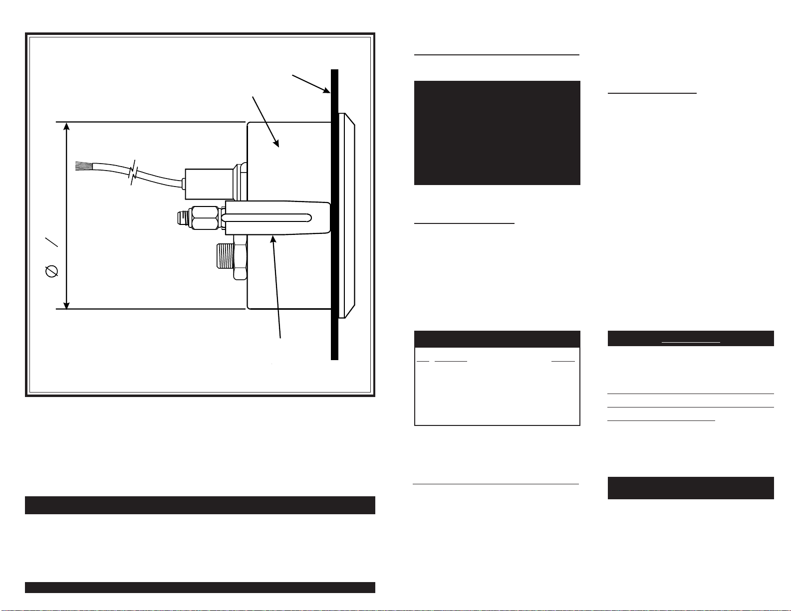
Diagram A
Gauge Dimensions
PP
*DXJH
0RXQWLQJ
%UDFNHW
3D Q H O
1. Route the tube from the gauge to the
engine. DO NOT CRIMP the tubing
closed during routing. A rubber grommet
is recommended around the tubing where
it passes through the firewall.
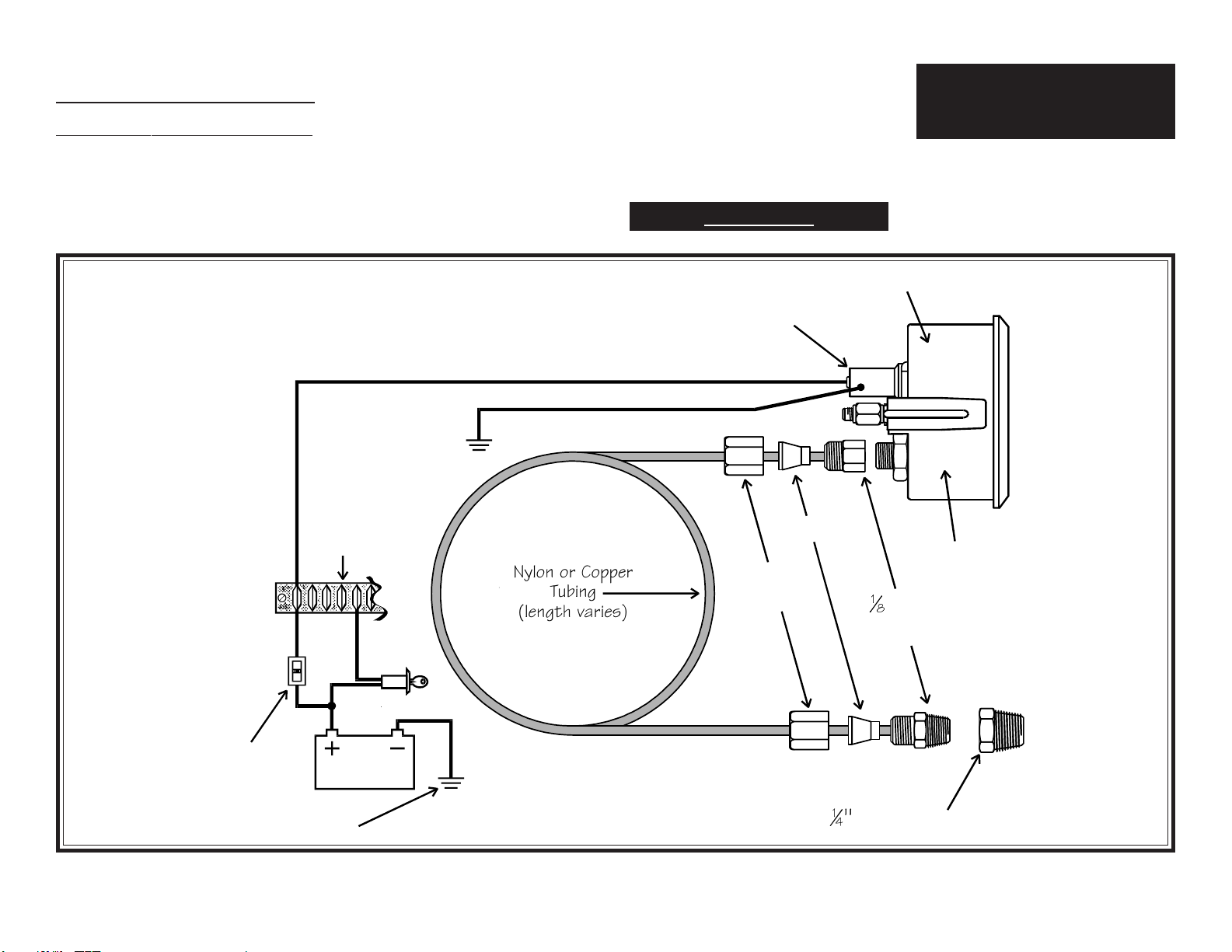
Diagram B
Gauge hookup and lamp wiring information
Gauge Hookup and Lamp Wiring:
2. Attach one end of the tubing to the
gauge using a 1/8" adapter, ferrule and seal-
ing nut, as shown in Diagram B.
3. Attach the other end of the tubing to
the engine using a ¹⁄₈" adapter, a ferrule and
a sealing nut. A ¼" adapter may be needed.
DO NOT OVERTIGHTEN THE SEAL-
ING NUTS OR YOU WILL DAMAGE
THE TUBING!
➋CONTINUE HERE 4. Run the wire from the gauge lamp socket
to the lighting circuit (a +12 volt source,
usually after the light switch fuse in the fuse
box). See Diagram B.
At this point, installation is complete.
Re-check the routing of the tube from the
gauge to the engine.
CAUTION:
Make sure the tube is absolutely free
from moving and/or hot engine com-
ponents, and that it is totally free of
kinks.
Start the engine and turn on the lights to
make sure the gauge illumination functions
properly. If it doesn't, recheck your con-
nections and your wiring. Check all tub-
ing connections for leaks.
1\ORQRU&RSSHU
7XELQJ
OHQJWKYDULHV
6HDOLQJ
1XWV
)HUUXOHV
%DWWHU\
/DPS6RFNHW
6HOIJURXQGHGWR
LQVWUXPHQWKRXVLQJ
*URXQG
)XVH
%R[
/LJKW
6ZLWFK
*URXQGWR
LQVWUXPHQW
KRXVLQJ
%HVXUHKRXVLQ
J
LVJURXQGHG
137
$GDSWRU
é$GDSWRU
3UHVVXUH
*
DXJH
Siemens VDO Limited Warranty
VDO North America warrants all merchandise against defects in factory workmanship and materials for a period of 24 months after purchase. This
warranty applies to the first retail purchaser and covers only those products exposed to normal use or service. Provisions of this warranty shall not
apply to a VDO product used for a purpose for which it is not designed, or which has been altered in any way that would be detrimental to the
performance or life of the product, or misapplication, misuse, negligence or accident. On any part or product found to be defective after examination
by VDO North America, VDO North America will only repair or replace the merchandise through the original selling dealer or on adirect basis. VDO
North America assumes no responsibility for diagnosis, removal and/or installation labor, loss of vehicle use, loss of time, inconvenience or any other
consequential expenses. The warranties herin are in lieu of any other expressed or implied warranties, including any implied warranty of merchant-
ability or fitness, and any other obligation on the part of VDO North America, or selling dealer.
(NOTE: This is a Limited Warranty as defined by the Magnuson-Moss Warranty Act of 1975.)
Siemens VDO .http://sso-usa.siemensvdo.com/ .Phone: 1-800-265-1818
Mechanical Vacuum Gauge
Installation Instructions
Instruction Sheet # 0 511 011 795
Rev. 07/03
INSTRUCTIONS FOR THE INSTALLATION OF THE MECHANICAL VACUUM GAUGE ARE
CONTAINED HEREIN. USE IS RESTRICTED TO 12-VOLT NEGATIVE GROUND
ELECTRICAL SYSTEMS. LIGHT BULB, IF SUPPLIED, IS 12 VOLTS.
Siemens VDO®
Tools and Materials Needed For Installation:
16 Gauge stranded, insulated wire
Insulated ¼" spade connectors
2⁵⁄₈" hole saw
Drill and drill bit set
Half-round file
Tape measure or ruler
Small tools: wrench or nut driver, utility
knife, pliers, etc.
Tubing kit and various engine adapters To Begin, go to #➊
The bezel diameter is only a few mil-
limeters larger than the gauge itself.
With that in mind, measure and pre-
cisely mark the gauge location be-
fore cutting any holes!
CAUTION!!!
Item Description Quantity
1. Vacuum Gauge (2⁵⁄₈" [52 mm] diameter) 1
2. Lamp Socket 1
3. Light Bulb 1
4. VDO Mounting Bracket and nuts 1
5. Installation Instructions 1
Parts List
Your VDO mechanical vacuum gauge fea-
tures the latest illumination technology and
a rugged design to insure years of durable
and reliable operation. These instruments
require a tubing kit to complete installa-
General Information:
1. Select the location where you will mount
the gauge, and mark a center point for a
hole (or use a VDO Mounting Accessory
[1,2, & 3 hole chrome and black] or a VDO
Mounting Cup [chrome or black]).
2. Cut a 2 ⁵⁄₈" (65 mm) diameter hole for
the vacuum gauge. Place the instrument
into the hole. If the gauge is too snug, use
a file to slightly enlarge the opening until
the gauge fits properly. See Diagram A.
4. Slip the mounting bracket over the
mounting bolts on the back of the gauge.
Screw on the accompanying nuts. Tighten
the nuts until the gauge can no longer be
rotated by hand. DO NOT OVER-
TIGHTEN!
Gauge Installation:
➊BEGIN HERE tion with various engines. You may pur-
chase such a kit (with different lengths of
tubing and of different styles) from your
VDO dealer.
CAUTION:
Read these instructions
thoroughly before making installation.
Donotdeviatefromassemblyor wiring
instructions. Alwaysdisconnectbattery
ground before making any electrical
connections. Ifindoubt,please contact
yourdealer orVDOInstruments at1-800-
265-1818.
Diagram A
Gauge Dimensions
PP
*DXJH
0RXQWLQJ
%UDFNHW
3D Q H O

1. Route the tube from the gauge to the
engine. DO NOT CRIMP the tubing
closed during routing. A rubber grommet
is recommended around the tubing where
it passes through the firewall.
Diagram B
Gauge hookup and lamp wiring information
7)LWWLQJ
WR0DQLIROG
9DFXXP+RVH
9DFXXP*DXJH
1\ORQRU&RSSHU
7XELQJ
OHQJWKYDULHV
6HDOLQJ
1XWV
)HUUXOHV
%DWWHU\
/DPS6RFNHW
6HOIJURXQGHGWR
LQVWUXPHQWKRXVLQJ
*URXQG
)XVH
%R[
/LJKW
6ZLWFK
*URXQGWR
LQVWUXPHQW
KRXVLQJ
%HVXUHKRXVLQJ
LVJURXQGHG
137
$GDSWRU
Gauge Hookup and Lamp Wiring:
2. Attach one end of the tubing to the
gauge using a 1/8" adapter, ferrule and seal-
ing nut, as shown in Diagram B.
3. Attach the other end of the tubing to
the engine using a T-fitting, 1/8" adapter, a
ferrule and a sealing nut.
DO NOT OVERTIGHTEN THE SEAL-
ING NUTS OR YOU WILL DAMAGE
THE TUBING!
➋CONTINUE HERE 4. Run the wire from the gauge lamp socket
to the lighting circuit (a +12 volt source,
usually after the light switch fuse in the fuse
box). See Diagram B.
At this point, installation is complete.
Re-check the routing of the tube from the
gauge to the engine.
CAUTION:
Make sure the tube is absolutely free
from moving and/or hot engine com-
ponents, and that it is totally free of
kinks.
Start the engine and turn on the lights to
make sure the gauge illumination functions
properly. If it doesn't, recheck your con-
nections and your wiring. Check all tub-
ing connections for leaks.
Siemens VDO Limited Warranty
VDO North America warrants all merchandise against defects in factory workmanship and materials for a period of 24 months after purchase. This
warranty applies to the first retail purchaser and covers only those products exposed to normal use or service. Provisions of this warranty shall not
apply to a VDO product used for a purpose for which it is not designed, or which has been altered in any way that would be detrimental to the
performance or life of the product, or misapplication, misuse, negligence or accident. On any part or product found to be defective after examination
by VDO North America, VDO North America will only repair or replace the merchandise through the original selling dealer or on a direct basis. VDO
North America assumes no responsibility for diagnosis, removal and/or installation labor, loss of vehicle use, loss of time, inconvenience or any other
consequential expenses. The warranties herin are in lieu of any other expressed or implied warranties, including any implied warranty of merchant-
ability or fitness, and any other obligation on the part of VDO North America, or selling dealer.
(NOTE: This is a Limited Warranty as defined by the Magnuson-Moss Warranty Act of 1975.)
Siemens VDO .http://sso-usa.siemensvdo.com/ . Phone: 1-800-265-1818
Electric Temperature, Pressure,
Fuel Gauge or Voltmeter
Installation Instructions
Instruction Sheet # 0 511 011 812
Rev. 07/03
INSTRUCTIONS FOR THE INSTALLATION OF THE ELECTRIC TEMPERATURE,
PRESSURE, FUEL GAUGE AND/OR VOLTMETER ARE CONTAINED HEREIN. USE IS
RESTRICTED TO 12-VOLT NEGATIVE GROUND ELECTRICAL SYSTEMS. LIGHT BULB,
IF SUPPLIED, IS 12 VOLT.
Siemens VDO ®
Tools and Materials Needed For Installation:
16 Gauge stranded, insulated wire
Insulated ¼" spade connectors
2 ⁵⁄₈" hole saw
Drill and drill bit set
Half-round file
Tape measure or ruler
Small tools: wrench or nut driver, utility
knife, pliers, etc.
Various engine adapters
1. Select the location for the instrument
and cut either a 2 ⁵⁄₈" hole (or use a VDO
mounting accessory [1,2, & 3 hole chrome
and black] or VDO mounting cup [chrome
Gauge Installation:
To Begin, go to #➊
➊BEGIN HERE or black]).
2. Insert the gauge and secure it.
DO NOT OVERTIGHTEN.
(Refer to Diagram A)
NOTE: On all oil and water temperature
gauges, 14-gauge wire is required for gauge
ground; it must be a dedicated ground to
insure gauge accuracy and to eliminate any
erratic gauge readings.
1. Run wires from the instrument location
through the firewall to:
a) the positive (+) terminal on
the battery (after the ignition
switch, and after the fuse box);
b) the light switch (also after the
fuse in the fuse box);
Wiring the Gauge:
Ù
[text continues at #Ë]
IMPORTANT: Mounting dimensions
vary for different gauges. Please be cer-
tain to follow the instructions for your
specific gauge as described below.
The bezel diameter is only a few mil-
limeters larger than the gauge itself.
With that in mind, measure and pre-
cisely mark the gauge location be-
fore cutting any holes!
CAUTION!!!
Item Description Quantity
1. Temperature, Pressure, Fuel Gauge or
Voltmeter
(2⁵⁄₈" [65 mm] diameter) 1
2. Lamp Socket 1
3. Light Bulb 1
4. Mounting bracket 1
5. Installation Instructions 1
Parts List
CAUTION:
Read these instructions
thoroughly before making installation.
Donotdeviatefromassemblyor wiring
instructions. Alwaysdisconnectbattery
ground before making any electrical
connections. Ifindoubt,please contact
yourdealer orVDOInstruments at1-800-
265-1818.
➌FINISH HERE
4. Ground the sender wire. On all pres-
sure and fuel gauges, the pointer will go
to 0. On all temperature gauges, the
pointer will go to the extreme right.
NOTE: Items 2,3, & 4 will be in the re-
verse operating condition when you are using
SW senders.
If these four functions occur as stated, the
instrument is in proper working order. If
the gauges do not respond as described
above, you probably have a faulty sender
or other sender problem.
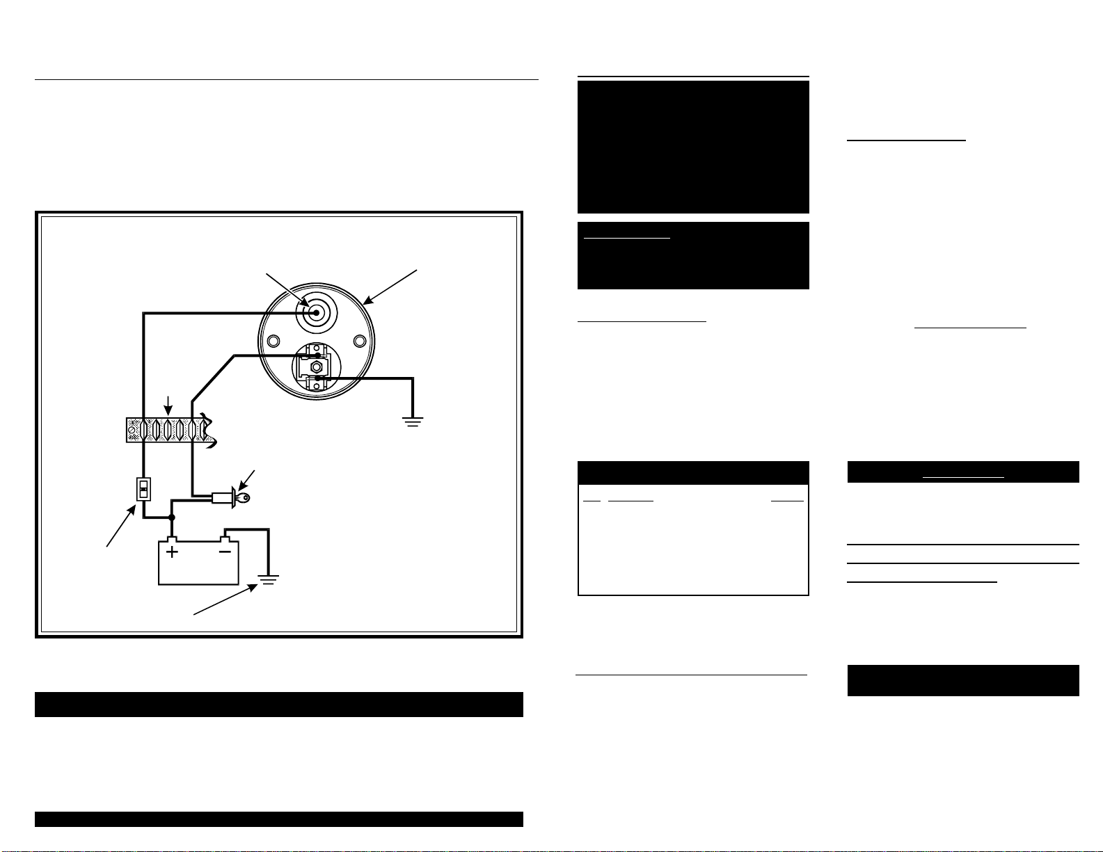
Diagram D
Proper wiring of the Voltmeter
%DWWHU\
9ROWPHWHU
/DPS6RFNHW
6HOIJURXQGHGWR
LQVWUXPHQWKRXVLQJ
*URXQG
)XVH
%R[
/LJKW
6ZLWFK
6ZLWFKHG
Y
+
–
*URXQGWR
FKDVVLV

Diagram A
Gauge dimensions
PP
*DXJH
0RXQWLQJ
%UDFNHW
3DQHO
➋CONTINUE HERE
c) a good, dedicated ground lo-
cation (i.e., where the negative
() battery pole is connected to
the chassis of the vehicle); and
d) from the instrument sender
terminal to the terminal on the
sending unit.
2. Connect the appropriate positive (+),
ground (negative []), and signal wires to
the gauge and gauge lamp socket as shown
in Diagram B or C.
3. If you are using a VDO sender with a
built-in warning contact terminal, run a
wire (again, minimum 16-gauge, stranded)
from the sender terminal marked WK to
one terminal on the warning light.
Run another wire from the other warning
light terminal to a switched ignition source.
NOTE: Do not use teflon tape on the sender
threads which act as an electrical ground source
for the unit.
Water temperature senders work best if
they are installed near the thermostat hous-
ing. Oil temperature senders can be used
to replace the manufacturers oil pan drain
plug. The oil pressure sender is installed
in the same location as the factory sender
or warning light switch.
Remember: These gauges measure ohm
resistance which is created by the sender.
The ohm range of the sender and gauge
MUST MATCH or the gauge will not be
accurate. VDO sells many gauges which
work with other manufacturers senders;
but you must know the correct sender ohm
range before you buy any of these gauges.
Diagram B
Proper wiring of the Temperature, Pressure or Fuel Gauge
Make sure the instrument is wired prop-
erly, then:
1. On all electric instruments, the pointer
will be to the extreme left when power is
off.
2. On pressure instruments, the pointer
will go to 0 when the power is turned on.
On temperature gauges, the pointer will
indicate current fluid temperature when
power is turned on. When power is ap-
plied to fuel gauges, the pointer will show
how much fuel is currently in the tank.
3. Pull the sender wire off the sender. On
pressure and fuel gauges, pointers go to the
extreme right; pointers go to the extreme
left on temperature instruments.
%DWWHU\
6LJQDO
*DXJH
*URXQGWR
FKDVVLV
/DPS6RFNHW
6HOIJURXQGHGWR
LQVWUXPHQWKRXVLQJ
*URXQG
)XVH
%R[
/LJKW
6ZLWFK
6ZLWFKHG
Y
s
+
*URXQG
6HQGHU
7HPSHUDWXUH
RU
RU
3UHVVXUH
)XHO
Troubleshooting:
Ù
[text continues at #Ì]

Web Site: http://sso-usa.siemensvdo.com/


Page 1
Tachometer Installation and Operation Instructions
For Street Eliminator, Comp Eliminator, Pro Eliminator, and Top Eliminator Tachometers
THE INSTRUCTIONS FOR INSTALLATION AND ELECTRICAL WIRING FOR THESE TACHOMETERS FOLLOW. USE IS RESTRICTED TO 12 VOLT NEGATIVE GROUND ELECTRICAL SYSTEMS.
Item Description Quantity
Parts List
1. Tachometer 1
2. Decals, 2 x 4 (not contingency decals) 2
3. 18-Gauge Wire, 4 1
4. 3-Conductor Shielded Wire, 10 1
5. Posi-Lock Connectors 4
6. Rubber Mounting Grommet 1
7. Contoured Mounting Foot 1
Tachometer Installation
CAUTION: Read these instructions thoroughly before mak-
ing installation. Do not deviate from assembly or wiring in-
structions. Always disconnect battery ground before making
any electrical connections. If in doubt, please contact your
dealer or VDO Instruments at 1-800-265-1818.
Installing the tachometer is a three-step process. First, you
must program the tachometer to match the number of cylin-
ders your engine has and the type of ignition your are using.
Next, you must determine where to mount the tachometer
and which optional mounting brackets, if any, you need.
Finally, after mounting the tachometer, you must wire it.
I. Programming the Tachometer
1. Start by removing the four (4) cap nuts and washers on
the back of the tachometer. (For the Street Eliminator, see
Diagram A; for the Comp Eliminator, Diagram B; for the
Pro Eliminator, Diagram C; and for the Top Eliminator,
Diagram D.)
2. Before removing the mounting cup, spray the five wires
with any of the following products: WD40, ARMOR-ALL,
or any rubber/vinyl protectorant. This will allow the wires
to slide through the rubber grommet.
3. Take off the back cap. Set the selector switches to match
the cylinder and ignition type you are using. Switches 1 & 2
will input the number of cylinders your engine has. Switch 3
applies only to the Top Eliminator. It allows you to choose
either 50 or 200 seconds of recording memory. We recom-
mend that you use the shortest memory practical for your
application. Switch 4 is used to input the type of ignition
system on which you are installing the tachometerelec-
tronic, CDI, or standard. For the selector switch settings
that apply to the model of Eliminator Tachometer you are
installing, consult either Diagram A, B, C, or D. Each ta-
chometer is preset to eight cylinder engines and electronic
ignitions (and the Top Eliminator to 50 seconds). You must
change the selector switches to match the number of cylin-
ders and the ignition your are using, or the tachometer will
not work properly. Should you ever need to replace the Type
194 light bulb, remove the back cap as you would to set the
Selector Switches.
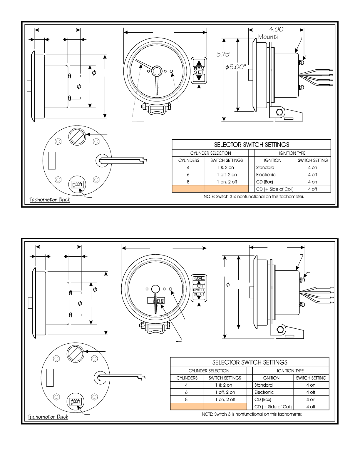
Diagram A
Street Eliminator Dimensions and Switch Settings
Magneto Interface Box #340 030
Remote Keypad Cable, 6 #240 207
Flush Dash Mounting Bracket #240 104
On-Dash Mounting Bracket #240 103
Optional Items Which May Be Needed:
Part # 0 511 012 253 Rev. 07/03
®
&'%R[
6KLIW3RLQWHU
0RXQWLQJ&XS
&DS1XW
7\SH%XOE
6HOHFWRU6ZLWFKHV
Siemens VDO Instruments
Page 2
Diagram B
Comp Eliminator Dimensions and Switch Settings
Diagram C
Pro Eliminator Dimensions and Switch Settings
6KLIW3RLQWHU
.H\SDG
6KLIW/LJKW
.H\SDG
6KLIW/LJKW
'LJLWDO'LVSOD\
5(&$//
7$&+
&/($5
5306(7
0RXQWLQJ&XS
&DS1XW
0RXQWLQJ&XS
&DS1XW
7\SH%XOE
6HOHFWRU6ZLWFKHV
7\SH%XOE
6HOHFWRU6ZLWFKHV

Page 3
For competition dash mounting, the rubber mounting grom-
met supplied can be used. This requires a 3½" hole. Re-
move the rubber grommet from the mounting ring and place
the tachometer into the hole. The mounting cup can be
used for a mounting bracket. Mounting without the grom-
met requires a 33
/
16
"hole. If the dash panel is ½" thick or
less, the mounting cup can be used for a bracket. Or, use a
modified in-dash bracket #240 104.
1. Select a location to mount the tachometer. Eliminator
Tachometers can be mounted in four different ways, depend-
ing on your preference. They can be: ¶ Column or roll bar
mounted. A short contoured foot is included so you can
mount the tachometer this way. · In-dash shock mounted.
¸ In-dash flush mounted with an optional U-bracket (#240
104). ¹Top-dash mounted with an optional long foot (#240
103) for stability.
Diagram D
Top Eliminator Dimensions and Switch Settings
4. After you have correctly positioned the selector switches
to exactly match your cylinder and ignition type, reassemble
the mounting cup to the rear of the tachometer with the
four (4) cap nuts.
II. Mounting the Tachometer
2. Mount the tachometer, making sure it does not rest against
glass, the windshield post, or the roll bar. (NOTE: To en-
sure proper operation, don't mount the tachometer too close
to any electrical items like an ignition system box, coils, or
an electrical fuel pump. The wires from these shouldn't be
routed by the tachometer, either.) Recommended installa-
tion is on the steering column using a band clamp available
at any local auto parts store. In some instances the drilling
of new holes for the repositioning of the keypad may be nec-
essary. For mounting on the dash, use the optional long
mounting bracket #240 103. Use the holes provided in the
bracket to secure the tachometer. Flush dash mounting re-
quires a 4¾" hole and the optional U-bracket #240 104.
3. The keypad can be remote mounted using the optional 6'
remote cable #240 207. Remove the keypad from the mount-
ing ring, then remove the mounting cup. Unplug the cable
from the back of the tach housing. Insert the male end of
the extension cable into the back of the tach. Then insert
the male end of the control pad cable into the female end of
the extension cable. Reattach the mounting cup, then mount
the keypad in the location of your choice.
1. Remove the key from the ignition and disconnect the
negative terminal from the battery post.
III. Wiring the Tachometer
2. Wire the tachometer to the vehicle as shown in Diagram
H on Page 4. Please understand that proper wiring must be
maintained throughout your vehicle. If it isnt, the tachom-
eter may pick up signals that have been produced by electri-
cal devices other than the ignition system. Dont coil up
excess tachometer wires during installation. Cut wires and
cables to length, and route them making sure they cant be
0RXQWLQJ&XS
&DS1XW
7\SH%XOE
6HOHFWRU6ZLWFKHV
.H\SDG
6KLIW/LJKW
'LJLWDO'LVSOD\
5(&$//
7$&+
&/($5
530 6(7

Page 4
5('
:+,7(
%/$&.
5('
:+,7(
%/$&.
6+,(/'
7RS 9LHZ
7R
0DJQHWR 7R
7DFKRPHWHU
&211(&7 $7 0$*1(72 (1' &211(&7 $7 7$&+20(7(5 (1'
5('
:+,7(
%/$&.
6+,(/'
5('
%/$&.
:+,7(
7R 6ZLWFKHG 3RZHU WR %DWWHU\
7R 0DJQHWR 2XWSXW 7DFK 6LJQDO
7R *URXQG
7R 6KLHOG RQ 6LJQDO :LUH WR *URXQG
7R 7DFK 5HG 3RZHU
7R 7DFK %ODFN *URXQG
7R 7DFK *UHHQ 6LJQDO
pinched by pedals or levers. When running cables through
areas like firewalls, eliminate wire chafing by using chassis
grommets. Proper battery voltagefrom 10.5 to 16.5 volts
must be maintained in the vehicle during operation. Dont
use solid core ignition wires. Ignition wires must be in good
condition. If erratic tachometer readings occur, check all wires
for proper resistance values. Youll note that we have included
shielded cable and Posi-Lock Connectors for your tachom-
eter installation. We highly recommend that you use these
to help insure proper operation. Splice the wires from the
tachometer to the shielded cable using the Posi-Lock Con-
nectors as shown in Diagram E.
Diagram G
Wiring With and Without a Light Switch
Diagram F
Magneto Interface Box Wiring Instructions
Magneto Interface Box
#340 030
To
Magneto Tachometer
To
Diagram H
General Wiring Information
Diagram E
Connect tach wires to insulated cable with Posi-Locks
CdbY`gYbUU^TcQR_ed
9^cUbdUQSXgYbUY^d_Q]Q\UU^T
Uh`_cY^W_^\iRQbUgYbU
8Q^TdYWXdU^]Q\UU^Tc
Y^d_U^Tc_VRQbbU\
¯
°
±
3. Refer to your engine manual and/or the manufacturers
manual for the location of the tachometer signal connection
for a voltage-triggered tachometer. Typical connections are
found in the box below. Wire to a magneto ignition using the
optional Magneto Interface Box as shown in Diagram F.
For racing applications, connect both the red wire for power
and the white wire for illumination to the red wire in the
shielded cable used to connect the tach to the ignition.
This will cause the tachometer to stay illuminated continu-
ously during operation, but will help insure the shielding of
the tachometer. For non-racing applications, or applications
with a low risk of radio-frequency or electromagnetic inter-
ference, the white wire from the tachometer can be wired di-
rectly to the light switch for illumination only when the lights
are turned on. Refer to the wiring in Diagram G.
<(//2:
'2 127 86(
5('
%/$&.
*5((1
:+,7(
5('
%/$&.
:+,7(
:+,7(
6+,(/'('
&$%/(
/,*+7
6:,7&+
:,7+ /,*+7 6:,7&+
<(//2:
'2 127 86(
5('
5('5('5('
%/$&.
%/$&.
%/$&.%/$&.
*5((1
:+,7(
:+,7(
6+,(/'('
&$%/(
12,6( ),/7(5
,1387 287387
:,7+ 12,6( ),/7(5
:,7+287 /,*+7 6:,7&+
<(//2:
'2 127 86(
5('
%/$&.
*5((1
:+,7(
5('
%/$&.
:+,7(
6+,(/'('
&$%/(
:,7+287 /,*+7 6:,7&+
IGNITION
Standard
CD
Electronic
TYPE
points / breakerless
points
breakerless
MSD, ACCEL,
MALLORY, DDIS
(distributorless),etc.
CONNECTIONS
negative terminal on coil
points connection to CD box
positive terminal on coil
Tach output terminal on ignition
box, or points connection to
ignition box, or negative coil

Page 5
CONNECTING TO AN MSD-7AL IGNITION
1. Connect the tach using the 10' shielded cable included
with the tachometer. Peel approximately 3 to 4 inches of the
outside covering and aluminum shielding from the gray cable.
This will reveal four individual wires. Three will be insu-
lated and one will be uninsulated.
Diagram I
Wiring to MSD-7AL Ignition
2. Strip ½" of the insulation from the black, red and white
covered wires.
4. On the end of the white insulated wire, which will be
used for the tach signal, install a ¼" female spade terminal.
3. Combine the black and uninsulated wires, which will be
used for the ground, into a 5
16 " ring terminal.
5. Complete the ignition end of the cable by installing a ¼"
flange spade terminal on the red wire that will be used for
power.
6. Now connect the cable to the MSD-7AL box as shown
below in Diagram I. Connect the O ring with the black
and uninsulated wire to the terminal labeled GROUND.
7. Slide the female terminal with the white insulated wire
onto the terminal labelled TACH.
8. Place the U connector with the red wire on the
terminal labeled IGNITION. Make sure all of your con-
nections are tight and clean.
10. Peel back approximately 1½" of the gray cover, and the
shield, from the tachometer end of the shielded cable. Cut
the uninsulated wire down to the base of the shielding. Do
notUNDER ANY CIRCUMSTANCESconnect the
shield to the tachometer.
9. Route the shielded cable through the car as desired. Make
sure no wires can be pinched by pedals, levers, etc. Then
cut the cable to length, leaving a little extra for error.
11. Strip about ½" of insulation from the ends of the wires.
Strip the same amount of insulation from the tachometer
wires. We strongly recommend using the provided Posi-
Lockconnectors for splicing the tachometer wires to the
shielded cable. Install them now. Refer to Diagram E.
12. Connect the black wire from the tachometer to the black
wire of the shielded cable (GROUND).
13. Connect the green wire from the tachometer to the white
wire in the shielded cable (TACH SIGNAL).
14. Finally, connect the red wire from the tachometer to the
red wire in the shielded cable. The remaining white
tachomter wire is for illumination, and is connected as
+ TACH
TACH
SIGNAL
Posi-Lock Connector
Page 6
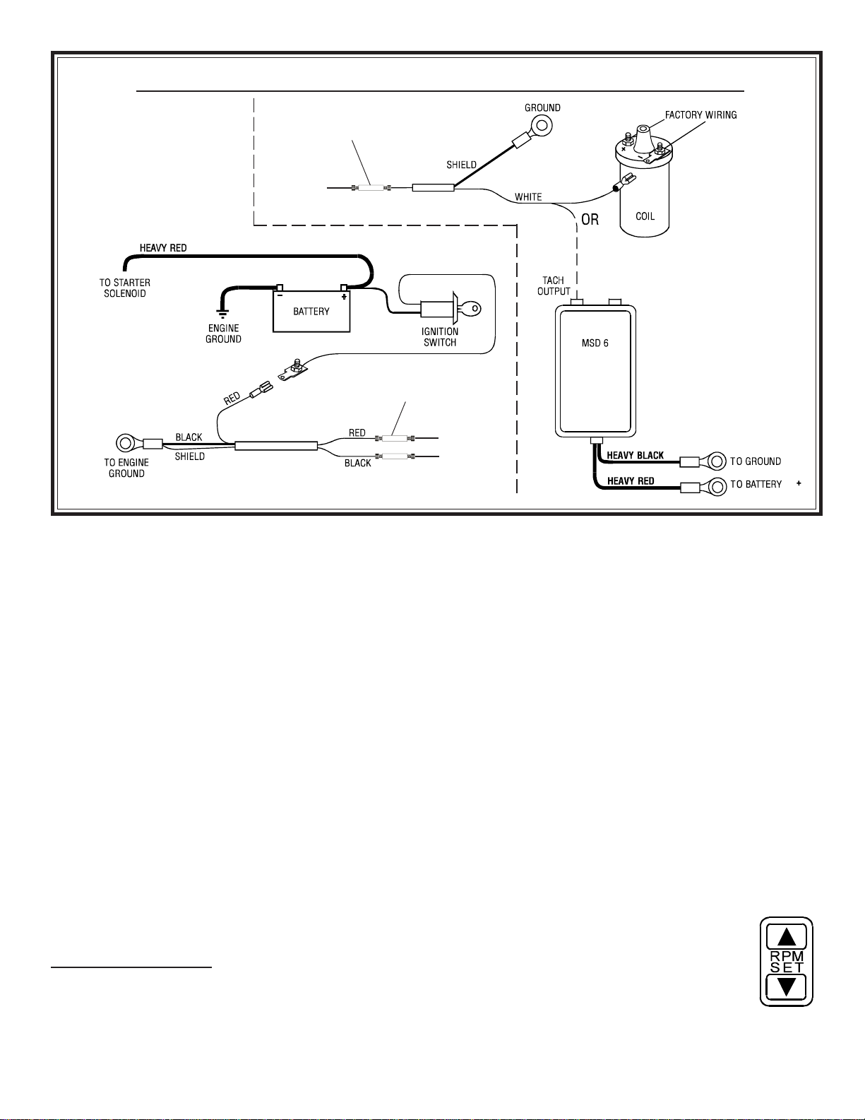
Diagram J
Wiring from the Tachometer to the Ignition Coil or MSD-6
described on Page 4, in the text and in Diagram G.
CONNECTING TO THE IGNITION COIL OR MSD-6
1. When connecting to the negative post of the ignition coil
or to the MSD-6 box, run the shielded cableincluded with
the tachometerfor the TACH SIGNAL, the POWER and
the GROUND wires.
I. Street Eliminator Operation
The Eliminator series consists of four different tachometers
the Street Eliminator, the Comp Eliminator, the Pro Elimi-
nator, and the Top Eliminator. Each is designed to give the
ultimate flexibility in operation and function. Operation of
these state-of-the-art tachometers is profiled in this section.
Tachometer Operation
This tachometer is designed for those individuals whose needs
include only engine RPM monitoring with a manual shift
pointer. This orange pointer, in the center of the tachom-
eter, can be used as a shift point indicator, a reminder not to
exceed a certain RPM, or as a stall point indicator.
1. To operate, move the shift pointer by simply turning the
easy-to-hold knob in the center of the tachometer face to
the RPM you wish to highlight.
This tachometer features the same manual shift pointer as
the Street Eliminator, as well as a super bright red LED shift
light. The Comp Eliminator shift pointer works the same
way as the Street Eliminator shift pointer. See the above
section for details. To set the LED shift light:
II. Comp Eliminator Operation
1. Press the RPM set button on the key pad.
2. Press the up arrow until the red pointer indi-
cates the RPM at which you would like the shift
light to illuminate.
3. To lower the RPM, press the down arrow.
4. Once you have chosen your desired RPM, push the RPM
set button in the center of the keypad again. The microprossor
2. Ground the shielded wire at the coil. Leave the shield
unconnected at the tachometer. Do not, UNDER ANY CIR-
CUMSTANCES, connect the shielding to the tachometer.
3. Connect the red tachometer POWER wire to the igni-
tion power, as seen above in Diagram J. Under normal cir-
cumstances, this connection should work properly. How-
ever, the power may need to be run through a separate
shielded cable directly from the battery, in order to escape as
much noise as possible. If this is the case, a 3-Amp, in-line
fuse and separate power switch should be used. Again, refer
to Diagram J, above.
YOU MUST USE TWO SETS OF SHIELDED WIRE FOR THIS INSTALLATION!
SHIELDED CABLE #1
SHIELDED CABLE #2
TACH SIGNAL
+
–TACH
POWER
Posi-Lock
Connector
Posi-Lock
Connector
Page 7
will now store the RPM you have selected, and return the
tachometer to the functional mode.
III. Pro Eliminator Operation
The Pro Eliminator not only gives you the advantages of an
LED shift light, but also allows you to set your RPM in pre-
cise increments of 10 RPM. And, the Pro Eliminator will
record and store the highest RPM your engine reaches during
the tachometers memory cyclethat is, since the last time
you cleared the memory. Set your shift point as follows:
1. Press the RPM SET button on the keypad. This will lift
the pointer from the LED display window.
5(&$//
7$&+
&/($5
5306(7
3. Should you
need to lower the
shift point, simply
press the down arrow.
2. Press the up arrow until the LED indi-
cates the desired
RPM shift point.
4. To return the tachometer to the operation mode, push
the button marked RPM SET again. The microprocessor
will store the shift point you set.
5. To activate the recall function and reveal the highest RPM
level reached during the memory cycle, press the RECALL
button on the keypad. The digital display will show the peak
RPM level achieved since you last pushed the CLEAR but-
ton. This display will last two seconds. To keep the peak
RPM level displayed longer than two seconds, press and hold
down the RECALL button. The display will disappear when
you release the RECALL button.
IV. Top Eliminator Operation
VDO Instruments Top Eliminator is the ultimate recording
tachometer. In addition to all of the previously mentioned
benefits in our other Eliminator tachometers, the Top Elimi-
nator enables you to record and play back the tachometer
readings for an entire 50-second or 200-second time period.
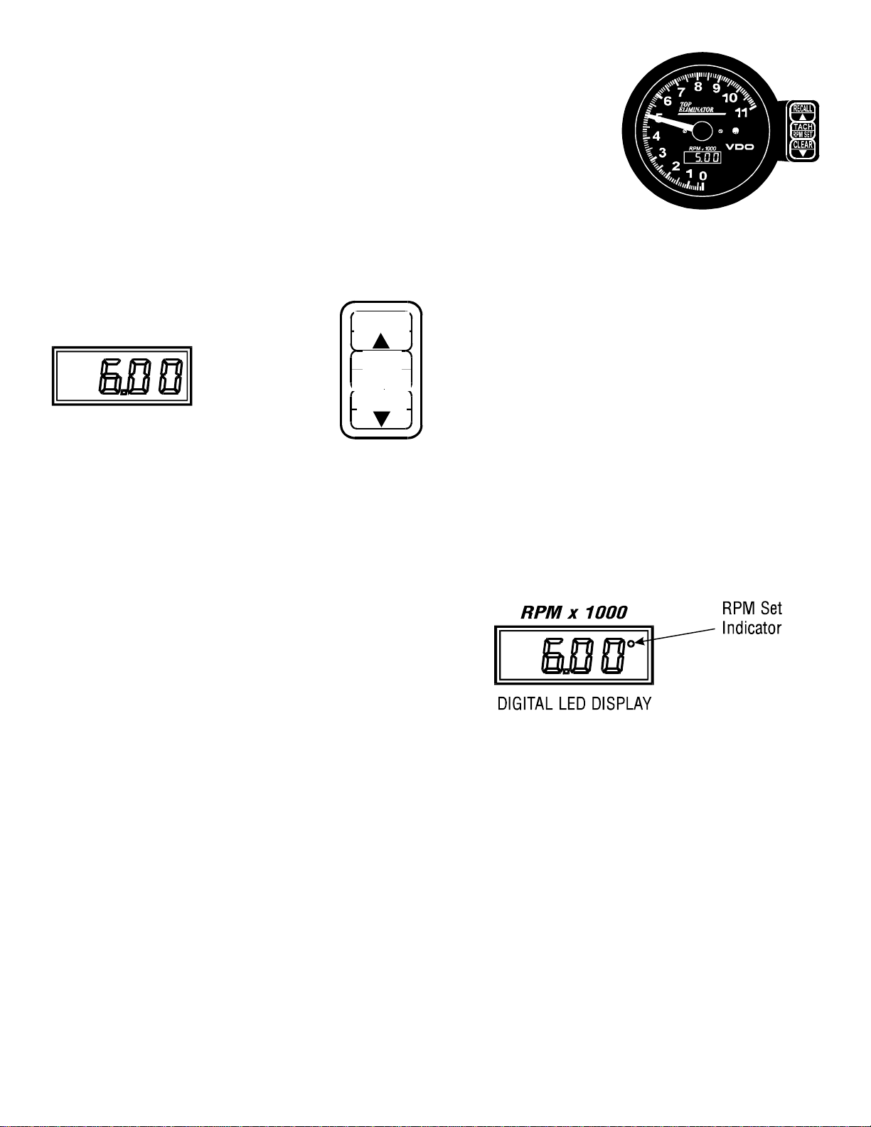
The tachometer has four modes of operation:
1. Normal tach mode (TACH); the tachometer is in the
normal TACH mode when first turned on. The LED
display will show 6.00.
2. Shift light RPM set mode (RPM SET); the RPM SET
mode is used for setting the RPM level for the shift
light.
3. Recording mode; the tachometer is capable of record-
ing 50 seconds or 200 seconds of the tachometers ac-
tivity.
4. Playback mode (RECALL); the tachometer will play
back the recording it made of the tachometer run in
slow motionshowing elapsed time and RPM values.
1. A 4-digit LED display
at the six oclock position.
This shows the RPM shift
point (e.g. 6.00 = 6000
RPM). The display will also
indicate when you are re-
cording and will show actual elapsed time in the playback mode.
Look at the tachometer
and you will notice three
distinctive features:
3. Once you have input the desired RPM level, push the
RPM SET button once again. The tachometer shuttles back
to the TACH operating mode, and the digital display now
indicates the new shift point. The dot in the upper right
corner of the display will disappear, and the pointer will re-
turn to the actual engine RPMs.
1. Push the TACH/RPM SET button. Pushing this button
toggles the tachometer between the normal TACH mode
and the RPM SET mode. In the RPM SET mode you can set
the RPM at which you want the shift light to illuminate. To
set this shift point, make sure the tachometer is in the RPM
SET mode. You can tell when tach is in this mode by looking
at the digital display. A small dot appears next to the last
digit on the right when the tach is in the RPM SET mode.
3. A keypad mounted on the right side of the tach. This
keypad is used to shuttle the tachometer between its four
modes, to set the RPM value of the shift light, to record ta-
chometer activity, and to activate the playback. To operate
the keypad and set the tachometer:
2. An ultra-bright LED shift light at the 3 oclock position.
This will turn on and stay on as long as your engine exceeds
the pre-set RPM shift point.
2. Push the up arrow (s) until you reach the RPM speed at
which you wish the LED shift light to illuminate. If you go too
far, push the down arrow (t) until you get the shift point ex-
actly where you want it (in exact increments or decrements of
10 RPM). Changing the shift point from 6.00 to 8.34, for ex-
ample, changes the shift point value up from 6000 to 8340 RPM.
The shift light will come on at exactly 8430 RPM.
When the tach is in the RPM SET mode, the functions illus-
trated on the bottom half of each keypad button become active
(s, t, and RPM SET). Also, the RPM indicator needle
moves out of the way so you can easily read the LED display.

Page 8
THE TACH POINTER JUMPS ERRATICALLY, THE
SHIFT LIGHT FLASHES RANDOMLY, OR THE DIS-
PLAY SHOWING THE SHIFT POINT GOES BLANK
AND THE POINTER GOES TO 4000-6000 RPM RE-
GARDLESS OF ACTUAL SPEED
4. To record and playback, press the RPM SET button. The
tachometer will return to the normal TACH operating mode.
The functions designated on the top half of each keypad but-
ton will now be active.
5. Press the CLEAR button to erace any previous recordings.
When the memory is erased the display will display three dots
(
. . .
) to indicate that the tach is recording. During this cycle,
the tach will record for either 50 or 200 seconds, whichever
length you selected when you programmed the tachometer.
When the tach has finished recording, the display will again
display the RPM value you set as your shift point.
6. Press the TACHRPM SET button during recording if
you wish to stop that function and return to the normal
TACH operating mode. You can turn off your engine before
recording has been completed without losing any informa-
tion. The tachometer also will remember your latest record-
ing even if you remove the power or battery leads.
7. Press the RECALL button to play back what you have
recorded. Playback occurs in slow motionone-third ac-
tual timeso you can really study the information. The LED
display will show elapsed time while the pointer is showing
the RPM cycle captured during the recording period. As an
example, a ten-second run requires thirty seconds to view;
but the digital display will show ten seconds as it links the
real time of the run to the recording.
8. Press the TACHRPM SET button during playback if
you wish to return to the normal TACH operating mode.
The stored information will be saved until the next time you
press the CLEAR button.
Troubleshooting
A. LOW BATTERY VOLTAGE. The operating voltage for
the Eliminator Tachometer is 10.5 volts 16.0 volts.
The cause of any combination of theseworsened under rac-
ing conditionsis extreme electrical noise attributed to:
If the tach is turned off during replay and the pointer was
over 4000 RPM, the pointer may swing to full scale. Just
turn on power to the tach and the pointer will reset.
WHEN THE POINTER STAYS AT FULL SCALE
B. INADEQUATE WIRING. All wiring should be kept as
direct as possible without having excess wires coiled behind
the dash. Avoid bundling power wires with signal wires and
having loose-ended power wires. These will act as transmit-
ting antennas for noise generated by the ignition system, fuel
pump, etc. The MSD crank trigger or mag pickup ignition
trigger should not be routed near spark plug wires or high
current wires.
C. IGNITION WIRES. Solid core metallic wires, old wires
with cracked insulation, or wires with improperly crimped ends
or breaks in the conductors emit large amounts of electro-
magnetic interference (EMI). Ignition wires can be checked
for defects with a standard ohmmeter. Heli-core wires (MSD)
will read 150 ohms per foot. ACCEL spiral core wire will
read 500750 ohms per foot. Standard resistor wires will
read 500010,000 ohms per foot.
Correct these problems first. If tach problems persist
A. WHEN CONNECTING TO MSD-7AL: Connect the
tach using the shielded cable provided. Connect the shield
and ground wire to the ground post on the MSD box or the
main MSD ground. Connect the power wire to the ignition
terminal on the MSD box, and the signal wire to the tach
output terminal on the MSD box. At the tach end, connect
the red wire to power, the green wire to signal, and the black
wire to ground (see Diagram I on Page 5). DO NOT connect
the shield to the tach under any circumstances.
B. WHEN CONNECTING TO THE IGNITION COIL OR
MSD-6: When connecting to the negative post of the igni-
tion coil or to the MSD-6, run a separate shielded wire for
the signal and the power/ground wires. The shielded wire
from the coil should be grounded at the coil and the shield-
ing left unconnected at the tach end. The power may need
to be run through a shielded wire directly from the battery to
escape as much noise as possible. If you wire in this way, in-
sert a 3-Amp in-line fuse and a separate power switch
( See Diagram J on Page 6).
C. If the shielded wire provided doesnt eliminate all noise
interference, a noise filter should be installed on the power/
ground wires, as close as possible to the tach. Noise filters
Radio Shack #270-051 or MSD #8830will eliminate any
remaining noise on the power wire from the ignition system,
fuel pump, alternator (if equipped), relays, etc. The tachs
white illumination wire may also need to be connected with
the red power wire after the noise filter. See Diagram G on
Page 4. These solutions should solve any problem you en-
counter. But if you still need assistance, call our Technical
Service Coordinator at 1-800-265-1818.
Siemens VDO Automotive Limited Warranty
Siemens VDO Automotive warrants all merchandise against defects in factory
workmanship and materials for a period of 24 months after purchase. This warr-
anty applies to the first retail purchaser and covers only those products exposed
to normal use or service. Provisions of this warranty shall not apply to a VDO
product used for a purpose for which it is not designed, or which has been
altered in any way that would be detrimental to the performance or life of the
product, or misapplication, misuse, negligence or accident. On any part or prod-
uct found to be defective after examination by Siemens VDO Automotive,
Siemens VDO Automotive will only repair or replacethe merchandise through the
oringinal dealer or on direct basis. Siemens VDO Automotive assumes no respon-
sibility for diagnosis, removal and/or installation labor, loss of vehicla use, loss
of time, inconvenience or any other consequential expenses. The warranties herin
are in lieu of any other expressed or implied warranties, including any implied
warranty of merchantabilty or fitness, and any other obligation on the part of
Siemens VDO Automotive, or selling dealer.
VDO Instruments .http://sso-usa.siemensvdo.com/ .Phone: 1-800-265-1818
Table of contents
Popular Measuring Instrument manuals by other brands

Powerfix Profi
Powerfix Profi 278296 Operation and safety notes

Test Equipment Depot
Test Equipment Depot GVT-427B user manual

Fieldpiece
Fieldpiece ACH Operator's manual

FLYSURFER
FLYSURFER VIRON3 user manual

GMW
GMW TG uni 1 operating manual

Downeaster
Downeaster Wind & Weather Medallion Series instruction manual

Hanna Instruments
Hanna Instruments HI96725C instruction manual

Nokeval
Nokeval KMR260 quick guide

HOKUYO AUTOMATIC
HOKUYO AUTOMATIC UBG-05LN instruction manual

Fluke
Fluke 96000 Series Operator's manual

Test Products International
Test Products International SP565 user manual

General Sleep
General Sleep Zmachine Insight+ DT-200 Service manual


