A5E02423026D DS01 Seite 2 von 2 page 2 of 2
Bild / Figure 6
Bild / Figure 7
Bild / Figure 8
Bild / Figure 9
Bild / Figure 10
Bild / Figure 11
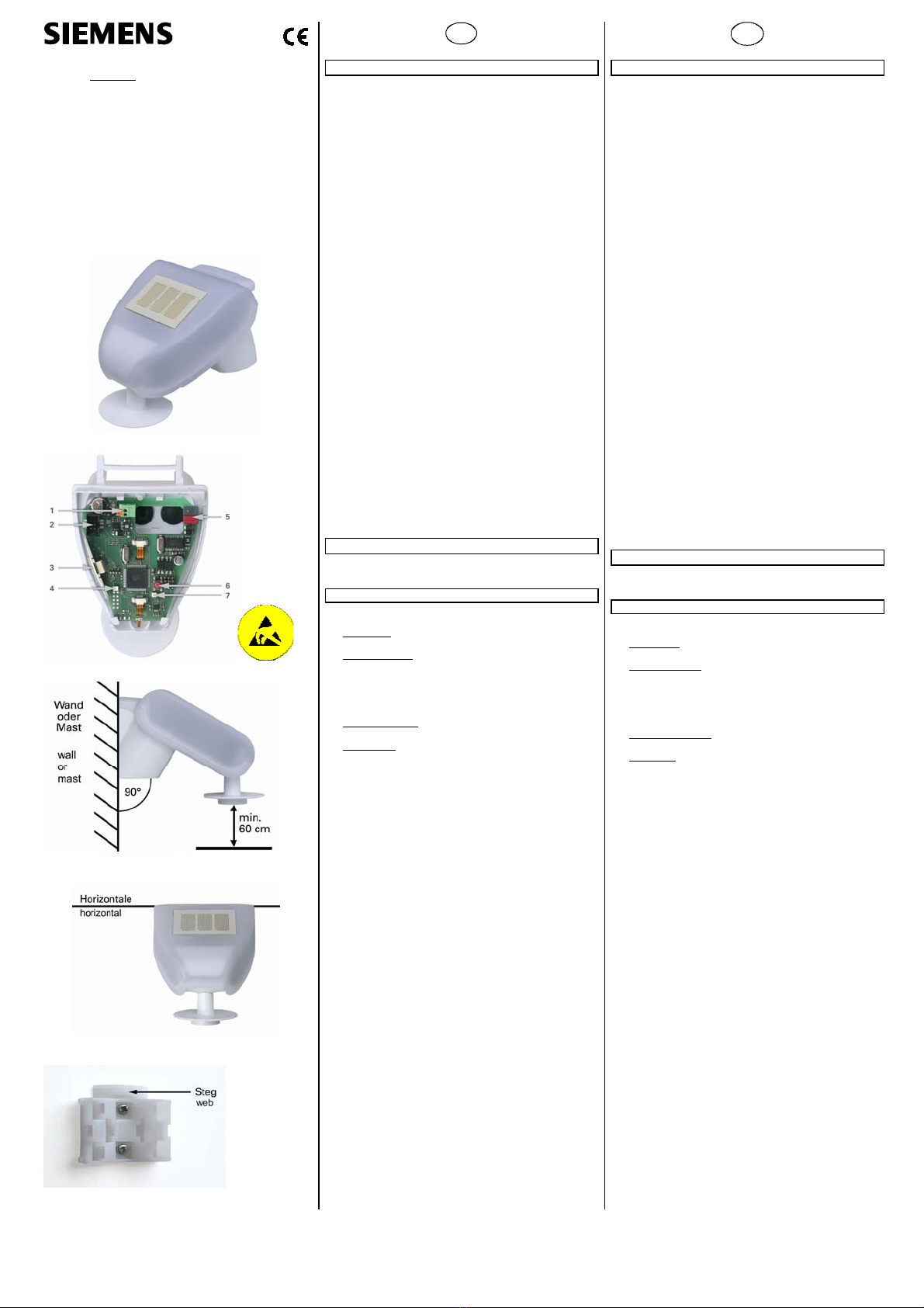
Lage und Funktion der Anzeige- und Bedienelemente
siehe Bild 2
1 Federkraftklemme Hilfsspannung AC 20 V / DC 24 V
2 Steckplatz für Kabelverbindung zum Niederschlagssensor im
Gehäusedeckel
3 GPS-Antenne
4 LED für GPS-Signal
5 Busklemme
6 Inbetriebnahme-Taste
7 Inbetriebnahme-LED
Montage und Verdrahtung
Standort
Wählen Sie eine Montageposition am Gebäude, wo Wind, Regen
und Sonne ungehindert von den Sensoren erfaßt werden kön-
nen. Es dürfen keine Konstruktionsteile über der Wetterstation
angebracht sein, von denen noch Wasser auf den Nieder-
schlagssensor tropfen kann, nachdem es bereits aufgehört hat
zu regen oder zu schneien. Die Wetterstation darf nicht durch
den Baukörper oder zum Beispiel Bäume abgeschattet werden.
Unter der Wetterstation muss mindestens 60 cm Freiraum be-
lassen werden, um eine korrekte Windmessung zu ermöglichen
und bei Schneefall ein Einschneien zu verhindern.
Magnetfelder, Sender und Störfelder von elektrischen Verbrau-
chern (z. B. Leuchtstofflampen, Leuchtreklamen, Schaltnetzteile
etc.) können den Empfang des GPS-Signals stören oder unmög-
lich machen.
Die Wetterstation muss an einem Mast oder einer senkrechten
Wand montiert (siehe Bild 3) und in der Querrichtung horizontal
(waagerecht) ausgerichtet werden (siehe Bild 4).
Die Befestigungsseite der Wetterstation sollte möglichst nach
Norden zeigen.
Montage
Der mitgelieferte kombinierte Wand- / Masthalter ist bei Liefe-
rung mit Klebestreifen an der Gehäuserückseite befestigt.
Wandmontage:
Befestigen Sie den Halter senkrecht mit der ebenen Seite zur
Wand, den halbmondförmigen Steg nach oben (siehe Bild 5).
Mastmontage:
Befestigen Sie den Halter mit der geschwungenen Seite zum
Mast, Steg nach unten (siehe Bild 6).
Ansicht der Rückwand und Bohrplan:
Bemaßung der Gehäuserückseite mit Halter: siehe Bild 7,
Bohrplan: siehe Bild 8.
Vorbereitung der Wetterstation:
Der Deckel der Wetterstation mit dem Regensensor ist am unte-
ren Rand rechts und links eingerastet. Nehmen Sie den Deckel
von der Wetterstation ab (siehe Bild 9). Gehen Sie sorgfältig
vor, um die Kabelverbindung zwischen der Platine im Unterteil
und dem Regensensor im Deckel nicht abzureißen (Kabel mit
Stecker).
Führen Sie die Busleitung durch die Gummidichtungen an der
Unterseite der Wetterstation und schließen sie die Aderpaare für
Spannungsversorgung und Bus unter Berücksichtigung der Pola-
rität an die dafür vorgesehenen Klemmen an (siehe Bild 2).
Befestigen der Wetterstation:
Schließen Sie das Gehäuse, indem Sie den Deckel über das Un-
terteil stülpen. Der Deckel muss rechts und links mit einem
deutlichen „Klick“ einrasten. Prüfen Sie, ob Deckel und Unterteil
richtig verrastet sind! Bild 10 zeigt die korrekt geschlossene
Wetterstation von unten.
Schieben Sie nun das Gehäuse von oben in den montierten Hal-
ter. Die Zapfen des Halters müssen dabei in den Schienen des
Gehäuses einrasten (siehe Bild 11).
Die Wetterstation lässt sich bei Bedarf wieder nach oben aus
dem Halter herausziehen.
Hinweise:
Öffnen Sie die Wetterstation nicht, wenn Wasser (Regen) ein-
dringen kann. Schon wenige Tropfen könnten die Elektronik be-
schädigen
Achten Sie auf korrekten Anschluss. Ein Falschanschluss kann
zur Zerstörung der Elektronik der Wetterstation führen.
Bei der Montage ist darauf zu achten, dass der Temperatursen-
sor (kleine Platine an der Unterseite des Gehäuses) nicht be-
schädigt wird. Auch die Kabelverbindung zwischen Platine und
Regensensor darf beim Anschluss nicht abgerissen oder ge-
knickt werden. Der Windmesswert wird erstmalig 30 Sekunden
nach Anlegen der Versorgungsspannung übertragen.
Wartung
Die Wetterstation sollte regelmäßig (zweimal pro Jahr) auf
Verschmutzung überprüft und bei Bedarf gereinigt werden.
Bei starker Verschmutzung kann der Windsensor funktions-
unfähig werden, eine ständige Regenmeldung anliegen oder
keine Sonne mehr erkannt werden.
Zur Wartung und Reinigung sollte die Wetterstation sicher-
heitshalber immer vom Bus und der Versorgungsspannung
getrennt werden.
Location and Function of the Display and Operating Elements
see figure 2
1 Spring-force auxiliary voltage terminal AC 20 V / DC 24 V
2 Slot for cable connection to the precipitation sensor in the
casing lid
3 GPS antenna
4 LED for GPS signal
5 Bus terminal
6 Commissioning button
7 Commissioning LED
Mounting and wiring
Location
Select a position on the building where wind, rain and sunshine
can be recorded by the sensors without impairment. No struc-
tural elements should be mounted above the weather station
from which water could continue to drop on to the precipitation
sensor even after rain or snow has stopped. The weather station
should not be shaded by the building or e.g. trees. There must
be at least 60 cm free space under the weather station to allow
for correct wind measurements and to prevent the station from
being snowed in.
Magnetic fields, transmitters and interference fields from elec-
trical consumers (e.g. fluorescent lamps, neon signs, switch
mode power supplies etc.) can block or interfere with the recep-
tion of the GPS signal.
The weather station must be mounted on a mast or a vertical
wall (see fig. 3) and be leveled horizontally across the top (see
fig. 4).
The mounting side of the weather station should be directed to
north, if possible.
Mounting
The supplied combined wall / mast holder is fastened to the rear
side of the housing with adhesive tape on delivery.
Mounting on a wall:
Fasten the holder vertically with the even side to the wall, with
the crescent-shaped bar to the top (see fig. 5).
Mounting on a mast / pole:
Fasten the holder vertically with the curved side to the mast /
pole and the bar to the bottom (see fig. 6).
View of the rear wall and drilling scheme:
Dimensioning of the rear of the enclosure with holder:
see fig. 7, Drilling scheme: see fig. 8.
Preparing the weather station:
The lid of the weather station with the rain sensor is slotted in
on the right and the left at the lower edge. Remove the lid from
the weather station (see fig. 9). Be careful not to tear open the
cable connection between the circuit board in the bottom part
and the rain sensor in the lid (cable with plug).
Guide the bus connection through the rubber seals at the bot-
tom part of the weather station and connect the cable pairs for
the voltage supply and the bus to the provided terminals while
taking polarity into account (see fig. 2).
Fastening the weather station:
Close the enclosure by putting the lid over the lower part. The
lid must snap into place on the left and the right with a clear
“click”. Check that the lid and lower part are properly snapped
into place! Fig. 10 shows the correctly closed weather station
from below.
Now slide the enclosure into the mounted holder from above.
The pegs of the holder must slot into the rails of the enclosure
(see fig. 11).
When needed, the weather station can be pulled out of the
holder in an upwards direction.
Notes:
Do not open the weather station if water (rain) can get into the
inside. A few drops are enough to damage the electronics.
Take care that the connections are correctly made. A wrong
connection can destroy the electronics of the weather station.
During assembly care should be taken that the temperature sen-
sor (small circuit board on the lower part of the enclosure) is
not damaged. The cable connection between the circuit board
and the rain sensor may not be torn off or bent while making
the connection.
The wind measurement value is first transmitted 30 seconds af-
ter initiating the supply voltage.
Maintenance
The weather station should be regularly (twice per year)
checked for soiling and cleaned if necessary. In case of
strong pollution, the wind sensor may cease to function, rain
may be reported permanently or no more sun may be de-
tected.
During maintenance and cleaning, the weather station
should always be separated from the bus and the supply
voltage for safety purposes.
Technical Support
℡+49 (911) 895-7222
+49 (911) 895-7223
www.siemens.de/automation/support-request
Allgemeine Hinweise
•Die Bedienungsanleitung ist dem Kunden auszuhändigen.
•Ein defektes Gerät ist mit einem Rücklieferschein der zustän-
digen Vertriebsniederlassung an folgende Adresse zu sen-
den:
SIEMENS AG, Siemensstr. 10, D-93055 Regensburg
•Bei zusätzlichen Fragen zum Produkt wenden Sie sich bitte
an unseren Technical Support.
General Notes
•The operating instructions must be handed over to the client.
•A faulty device shall be sent with a Return Good Note for Ser-
vice provided by the appropriate Siemens sales office to the
following address:
SIEMENS AG, Siemensstr. 10, D-93055 Regensburg
•If you have further questions concerning the product please
contact our technical support.