Siemens AP 257/22 User manual

GAMMA instabus
Technical Product Information
February 2019
Weather Station (GPS) AP 257/22 5WG1 257-3AB22
Siemens SwitzerlandLtd DS01 Update: http://www.siemens.de/gamma-td
BuildingTechnologiesDivision
International Headquarters
Theilerstrasse 1a Siemens AG 2019
CH-6300 Zug Subject to change 1
Product and Applications Description
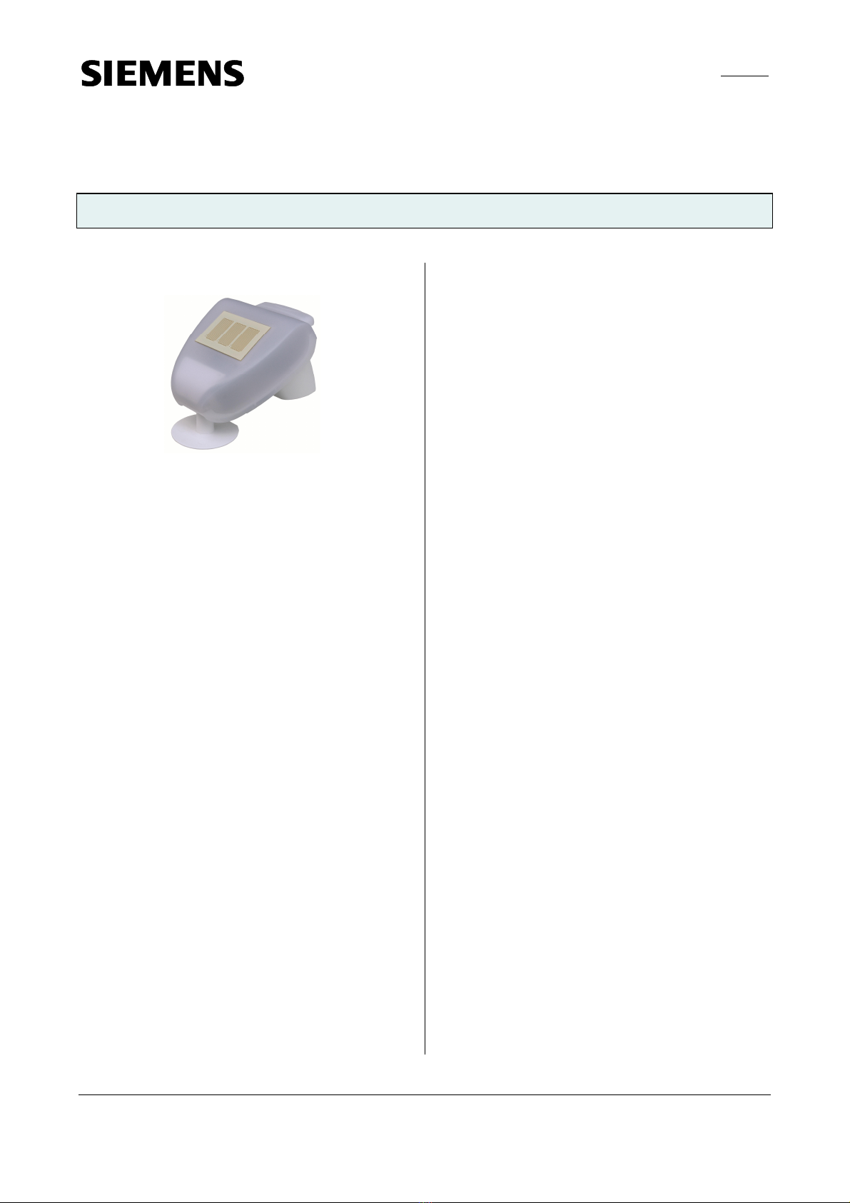
The AP 257/22 weather station (GPS) contains all sen-
sors, electronic systems for weather data analysis and
the bus coupler in one compact enclosure. It measures
wind speed, brightness and temperature, detects dusk /
dawn and precipitation and receives the GPS signal for
date and time.
Besides date and time, all measured values can be sent to
the bus in the EIS5 (DPT 9) format and each can be moni-
tored with up to 3 limit values. Limit values can be se-
lected as parameters or as communication objects. Per
day, the maximum wind speed, the maximum brightness
as well as the minimum and the maximum outside tem-
perature can be recorded and transmitted. The angles
(azimuth and elevation) at which the sun is shining can
be calculated from the date, the time of day and the
entered location coordinates, and can also be transmit-
ted via the bus.
The weather station not only allows for a simple solar
protection control, which activates or deactivates the
solar protection dependingon whether the sun is shining
or not. It can also activate a solar protection control for
up to 8 façades. In this case, the solar protection of a
façade is automatically activated only when the sun
shines on the respective façade and is deactivated as
soon as this is no longer possible, or the sun is no longer
shining.
For each façade, this façade control can be supplement-
ed by a shadow edge tracking control of the solar protec-
tion and a sun tracking control of horizontal / vertical
slats.
With the shadow edge tracking control, the solar protec-
tion is not lowered completely but only so far that the
sun can still shine into the room for a certain distance
(e.g. 50 cm), which can beset by a parameter. This way
the occupant of the room can look outside in the lower
part of the window, and plants on the windowsill can
receive sunshine.
With externally mounted Venetian blinds, the sun track-
ing control of slats can avoid heat influx into the room
due to sunshine and at the same time reduce electricity
costs for room lighting. In this case the slats are not
completely closed but set to follow the position of the
sun and automatically arranged in such a way, that the
sun cannot shine directly into the room. Between the
slats, however, diffuse daylight can enter the room and
contribute to a glare-free lighting of the room.
Besides wind alarm, frost alarm and precipitation alarm
in totalup to 8 alarm or error messagescan be combined
using a logical OR function to create a “Safety” communi-
cation object,which, in caseof analarm,moves the solar
protection into its safety position.
In addition, 4 AND-gates and 4 OR-gates are available
with 4 inputs each for additional logical combinations.
The weather station may also be used where GPS recep-
tion is not possible. In this case, date and time must be
sent to the weatherstationvia the bus.
For configuration, the engineering tool software ETS3 or
higher should be used, to provide a graphically optimal
display of the configuration menus of the weather sta-
tion.
The power supply of the electronics takes place via
AC20V or DC24V safetyextra-low voltage (SELV). For
the transmission of this voltage, the white / yellow twist-
ed pair of the bus cable can be used.
Application Program
The AP 257/22 weather station must be used together
with the application program “0701 CO Weather station
914201” which can be configured and loaded with the
Engineering Tool Software (ETS) from version ETS2 V1.3.
It is recommended to use the engineering tool software
ETS3 or higher, to provide a graphically optimal display
of the configuration menus of the weather station.

GAMMA instabus
Technical Product Information
February 2019
Weather Station (GPS) AP 257/22 5WG1 257-3AB22
Siemens SwitzerlandLtd DS01 Update: http://www.siemens.de/gamma-td
BuildingTechnologiesDivision
International Headquarters Siemens AG 2019
Theilerstrasse 1a Subject to change
CH-6300 Zug 2
Installation Instructions
If the weather station has been damaged, it must not be
commissioned.
VWARNING
•The device must be mounted and commissioned by an
authorised electrician.
•For planning and construction of electric installations,
the relevant guidelines, regulations and standards of
the respective country are to be considered.
Technical Specifications
Sensors
•Wind sensor:
Measuring range:0 ... 35 m/s,
Resolution: 0.1 m/s
precision at ambient temperature-20…+50°C:
±22% of measured value with air flow from 45…315°
±15% of measured value with air flow from 90…270°
(air flow onto the front equals 180°)
•Brightness sensor:
Measuring range: 0 ... 150.000 lux,
Resolution at: 0 ... 120 lux 1 lux
121 ... 1.046 lux 2 lux
1.047 ... 52.363 lux 63 lux
52.364 ... 150.000 lux 423 lux
Precision: ±20% at 0 lx … 10 klx
±15% at 10 klx … 150 klx
•Temperature sensor:
Measuring range:-30 ... +50 °C,
Resolution: 0.1 °C
Precision: ±0,5°C at +10…+50°C,
±1°C at -10…+10°C,
±1,5°C at-25…-10°C
•Rain sensor:
Heating: approx. 1.2 W
Voltage supply
•Bus voltage:via the bus line
•KNX bus current: 9 mA
•Auxiliary power sensor electronics:
AC 20 V (AC 12...28V) 50/60 Hzor
DC 24 V (DC 12...40V) max. 185 mA at DC 12V, residu-
al ripple < 10%, max. permissible cable length 100 m
•Power consumption: max. 2.3 VA
Operator elements
1 commissioning button: for switching over between
normal mode / addressing mode
Display elements
•1 red LED: for display of normal mode / addressing
mode (off / on)
•1 redLED: as controldisplay forGPS reception
Connections
•Voltage supply: plug terminals for solid conductors or
finely stranded conductors 0.5 ... 1.5mm²
•Bus connection: screwless bus terminal,
0.6... 0.8 mm ∅single-wire, insulation strip length 5
mm.
Mechanical data
•housing: plastic
•Dimensions :
approx. 118 mmx 96 mmx 77 mm (L x W x H)
•Weight:approx. 170 g
•Fire load: approx. 5360 kJ
•Mounting:Mast or wall mounting
Electrical safety
•Degree of pollution (according to IEC 60664-1): 2
•Type of protection (according to EN60529): IP 44
•Overvoltage category (according to IEC 60664-1): III
•Bus: safety extra-low voltage (SELV) DC 24 V
•Device complies with EN 50090-2-2
EMC requirements
complies with EN 50090-2-2
Environmental conditions
•Climatic conditions: EN 50090-2-2
•Ambient temperatureoperating: - 30 ... + 50 °C
•Ambient temperature non-op.: - 30 ... + 70 °C
•Relative humidity (non-condensing): 5 % … 93 %
Markings
KNX EIB
CE mark
complies with the EMC regulations (residential and func-
tional buildings), and low voltage regulations

GAMMA instabus
Technical Product Information
February 2019
Weather Station (GPS) AP 257/22 5WG1 257-3AB22
Siemens SwitzerlandLtd DS01 Update: http://www.siemens.de/gamma-td
BuildingTechnologiesDivision
International Headquarters
Theilerstrasse 1a Siemens AG 2019
CH-6300 Zug Subject to change 3
Location and Function of the Display and
Operating Elements and of the Sensors
Figure 1
1 Spring-force auxiliary voltage terminal AC 20V / DC 24V
2 Slot for cable connection to the precipitation sensor in
the casing lid
3 GPS antenna
4 LED for GPS signal
5 Bus terminal
6 Commissioning button
7 Commissioning LED
8 Brightness sensor
Figure 2
1Rain sensor
2 Temperature sensor
3 Wind sensor
4 Brightness sensor
Mounting and wiring
Location
Select a position on the building where wind, rain and
sunshine can be recorded by the sensors without im-
pairment. No structural elements should be mounted
above the weather station from which water could con-
tinue to drop on to the precipitation sensor even after
rain or snow has stopped. The weather station should
not be shaded by the building or e.g. trees. There must
be at least 60 cm free space around the weather station
to allow correct wind measurements and to prevent the
station from being snowed in. It is recommended to
install the weather station on a mast. It should be en-
sured that the highest point of all parts of buildings near
the weather station is 60 cm below the wind sensor of
the mounted weather station.
Magnetic fields, transmitters and interference fields from
electrical consumers (e.g. fluorescent lamps, neon signs,
switch mode power supplies etc.) can block or interfere
with the reception of the GPS signal.
The weather station must be mounted on a mast
(Ø approx. 50 –55mm)or averticalwall (see fig. 3) and
be leveled horizontally across the top (see fig. 4).
The wind sensor of the weather station shall point to the
cardinal point of the sun at noon, if possible. This means
South in the northern hemisphere, and North in the
southern hemisphere (see fig. 3).
Figure 3
Cardinal point of the sun at noon
4

GAMMA instabus
Technical Product Information
February 2019
Weather Station (GPS) AP 257/22 5WG1 257-3AB22
Siemens SwitzerlandLtd DS01 Update: http://www.siemens.de/gamma-td
BuildingTechnologiesDivision
International Headquarters Siemens AG 2019
Theilerstrasse 1a Subject to change
CH-6300 Zug 4
Figure 4
Mounting
The supplied combined wall / mast holder is fastened to
the rear side of the housing with adhesive tape on
delivery.
Mounting on a wall:
Fasten the holdervertically with the even side to the
wall, withthe crescent-shaped barto the top (see fig. 5).
Figure 5
Mounting on a mast/ pole:
Fasten the holdervertically with the curvedside to the
mast / pole and the bar to the bottom (see fig. 6).
Figure 6
View of the rear wall and drilling scheme:
Dimensioningof the rear of the enclosure withholder:
see fig. 7,
drilling scheme: see fig. 8.
Figure 7
Figure 8
Preparing the weather station:
The lid of the weather station with the rain sensor is
slotted inon the right and the left at the lower edge.
Remove the lid from the weather station (see fig. 9).
Figure 9
Be careful not to tear openthecable connection be-
tween the circuit board in the bottom part and the rain
sensor in the lid (cable with plug).
Guide the bus connection through the rubber seals at the
bottom part of the weather station andconnect the
cable pairs for the voltage supply and the bus to the

GAMMA instabus
Technical Product Information
February 2019
Weather Station (GPS) AP 257/22 5WG1 257-3AB22
Siemens SwitzerlandLtd DS01 Update: http://www.siemens.de/gamma-td
BuildingTechnologiesDivision
International Headquarters
Theilerstrasse 1a Siemens AG 2019
CH-6300 Zug Subject to change 5
provided terminals while taking polarity into account
(see fig. 1).
Fastening the weather station:
Close the enclosure by putting the lid over the lower
part. The lid must snap into place on the left and the
right with a clear “click”. Check that the lid and lower part
are properly snapped into place! Fig. 10 shows the cor-
rectly closed weather station from below.
Figure 10
Now slide the enclosure into the mounted holder from
above. The pegs of the holder must slot into the rails of
the enclosure (see fig. 11).
Figure 11
When needed, the weather station can be pulled out of
the holder in an upwards direction.
Notes:
Do not open the weather station if water (rain) can get
into the inside. A few drops are enough to damage the
electronics.
Take care that the connections are correctly made. A
wrong connection can destroy the electronics of the
weather station.
During assembly care should be taken that the tempera-
ture sensor (small circuit board on the lower part of the
enclosure) is not damaged. The cable connection be-
tween the circuit board and the rain sensor may not be
torn offor bent while making the connection.
The wind measurement value is first transmitted 30
seconds after initiating the supply voltage.
Maintenance
The weather station should be regularly (twice per year)
checked for soiling and cleaned if necessary. In case of
strong pollution, the wind sensor may cease to function,
rain may be reported permanently or no more sun may
be detected.
During maintenance and cleaning, the weather station
should always be separated from the bus and the supply
voltage for safety purposes.
General Notes
•The operating instructions must be handed over to the
client.
•Anyfaulty device is to be sent together with a return
delivery noteto the local Siemens office.
•If you have further questions concerningthe product,
please contact our technical support:
'+49 (911) 895-7222
7+49 (911) 895-7223
*support.automation@siemens.com
www.siemens.com/automation/support-request
Table of contents
Other Siemens Weather Station manuals
Popular Weather Station manuals by other brands

Auriol
Auriol 4-LD5501-1-2 Usage and safety instructions

Furuno
Furuno WS-200 Operator's manual

NATURE & DECOUVERTES
NATURE & DECOUVERTES 53150040 quick start guide

Sygonix
Sygonix 2739814 Important notes

Oregon Scientific
Oregon Scientific CW101 quick start guide

La Crosse Technology
La Crosse Technology S82967 instruction manual

La Crosse Technology
La Crosse Technology V15-AU Setup guide

Bresser
Bresser Temeo Hygro Quadro DLX instruction manual

BIOS WEATHER
BIOS WEATHER BW972 instruction manual

Sencor
Sencor SWS 12500 user manual

HoMedics
HoMedics EnviraStation DWS-200 Instruction manual and warranty information

Timex
Timex TX6180 instructions