Sierra Monitor Corporation PF2A7H User manual

URL http://www.smcworld.com
FOR AIR
Digital Flow Switch
Large Flow Rate Type
Instruction Manual
PF2A7□H Series

SAFETY 2
Model Indication Method 4
Name and Functions of Individual Parts 5
Installation 6
Example of Internal Circuit and Wiring 8
Setting 10
OUT1 Output Specifications 11
Function Setting 13
Other Functions 18
Specification 20
Full View with Dimensions 22
Thank you for purchasing the SMC PF2A7□H Series Digital Flow
Switch.
Please read this manual carefully before operating digital flow
switch and understand digital flow switch, its capabilities and limi-
tations. Please keep this manual handy for future reference.
OPERATOR
●This operation manual has been written for those who have
knowledge of machinery and apparatus that use pneumatic
equipment and have full knowledge of assembly, operation and
maintenance of such equipment.
●Please read this operation manual carefully and understand it
before assembling, operating or providing maintenance service
to the flow switch.
CONTENTS

32
SAFETY
IMPORTANT MESSAGES
WARNING
NOTE
Indicates a potentially hazardous situation
which could result in death or serious
injury if you do not follow instructions.
Gives you helpful information.
Read this manual and follow its instructions. Signal words such
as WARNING and NOTE will be followed by important safety
information that must be carefully reviewed.
Do not disassemble, remodel (including change of printed
circuit board) or repair.
An injury or failure can result.
Do not operate beyond specification range.
Fire, malfunction or switch damage can result.
Do not use with a combustible fluid.
Otherwise, a fire or an explosion or damage may potentially result.
This flow switch is for air only.
Do not operate in a combustible gas or explosive gas
atmosphere.
Fire or an explosion can result.
This flow switch is not an explosion proof type.
WARNING
The Digital Flow Switch and this manual contain essential information
for the protection of users and others from possible injury and
property damage and to ensure correct handling.
Please check that you fully understand the definition of the following
messages (signs) before going on to read the text, and always follow
the instructions.
NOTE
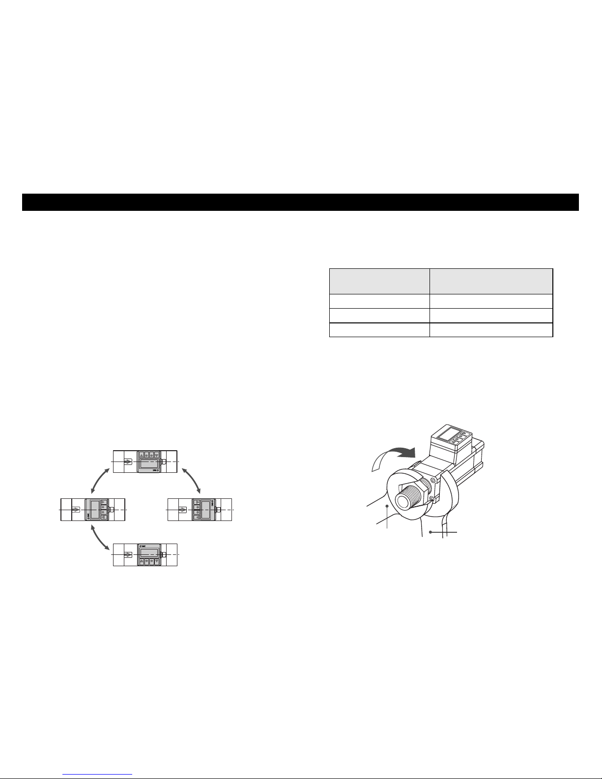
Follow the instructions given below when handling your flow
switch.
Otherwise, the switch may be damaged or may fail, thereby
resulting in malfunction.
・Do not drop it, bring it into collision with other objects or apply
excessive shock (490m/s2 or more).
・
Do not pull the lead wire with force nor lift the main unit by holding
the lead wire. (Pulling strength less than 49N)
・Wiring correctly.
・Do not wiring while power is on.
・
Do not wire with the same circuit of power line or high-voltage line.
・Do not use in a place in which water, oil, or a chemical is
splashes.
・Install a filter and/or mist seprator on the primary side (inlet
side) if foreign matter is feared to mix in a fluid.
・
Flush the dust in the piping with air blow before piping the switch.
・Do not push the setting buttons by a sharply pointed object.
・Apply the power.supply when the flow rate is zero.
・
Start measurement by the flow switch three seconds after turning
on the power.
・
Maintain the switch status for measurement output before setting
when initializing or setting a flow rate of the flow switch.
Measure after checking impacts to the equipment.
・
Opening and closing of flow passage by restrictor should be
within max.
measured flow rate value.

54
Unit Specification
No Symbol
:
Unit selection function provided
-
M: SI units fixed
Lead Wire Specification
No Symbol: Lead wire with connector 3m
N: None Lead wire with connector
PF2A7 H- -
Flow Rate Range
03: 150 to 3000 /min
06: 300 to 6000 /min
12: 600 to 12000 /min
NOTE1:
The revised Measurement Law of Japan
does not allow use of meters or measuring
instruments, which have a unit selection
function, in Japan.
NOTE2: The fixed unit
For instantaneous flow rate is : /min
For integrated flow rate is : , m3, m3×103
Port Screw Type
No Symbol: Rc N: NPT F: G
Body
Flow switch sensor body.
The arrow on the side of
the body indicates the
direction of flow.
Display Part
Output( OUT1)Lamp : Lit when OUT1 is ON.
Flickers when an overcurrent error occurs.
Flow display : Instantaneous flow, integrated flow and set value are
displayed.
Flow check display : Flickering interval varies depending on the flow.
Unit display : Selected unit is displayed. Single unit type is displayed
in SI unit ( /min or , m3, m3×
103).
▲Button (UP) : Selects a mode and increases a set ON/OFF value.
▼Button (
DOWN
):
Selects a mode and decreases a set
ON
/
OFF
value.
Button (MODE) : Changes the mode.
Button (SET) : Changes the mode and sets a set value.
*RESET
Pressing the
▲
and
▼
buttonssimultaneously will activate the RESET
function. Use this
function to clear errors
when a trouble occurs.
●
SET
●
MODE
Body
Lead wire with connector
on one end (option)
Piping Port(
OUT
)
Display part
Connector
Piping port
(IN)
U
P
DOWN
MODE
SET
Flow check display
Output(
OUT1
)
display
Button
(
MODE
)
▼
Button
(
DOWN
)
▲
Button
(
UP
)
Button
(
SET
)
FLOWSWITCH
ANR
OUT
Unit display
Flow display
●
MODE
●
SET
Accessories
(When no symbol is specified
for wiring in the type specification)
Lead wire with connector on one end
(3 m in length)
Names and Functions of Individual Parts
Output Specification
28: NPN open collector 1output
+ Analog output (1 to 5V)
29: NPN open collector 1output
+ Analog output (4 to 20mA)
68: PNP open collector 1output
+ Analog output (1 to 5V)
69: PNP open collector 1output
+ Analog output (4 to 20mA)
Model Indication Method
Piping Port
10: Port size 1 (Applicable for PF2A703H)
14: Port size 1・1/2 (Applicable for PF2A706H)
20: Port size 2 (Applicable for PF2A712H)
Piping port
This port connects with
pipeline. Use a pipe fitting to
connect with external pipeline.

76
Nominal size of screws
Rc 1 36 to 38
Rc 1・1/2 48 to 50
Rc 2 48 to 50
Before you mount a flow switch, read "SAFETY" and "Installation"
described in this chapter carefully to obtain safe and correct
measurement.
Mounting
●Use this flow switch under the specified operating pressure
range.
●Use this flow switch under the specified operating temperature
range.
●Withstand pressure is 2.25 MPa.
●Do not install a flow switch at a foothold position.
●Install a flow switch so that the flow direction agrees with the
arrow direction on the side of the body.
●Mount the body so that the bottom of the body does not face
upward.
●Provide a straight pipe length of more than eight times the pipe
diameter to upstream and downstream of the flow switch.
●
Set Display Part proper position taking the cable entry and display
position into account. Display Part rotates in 270 degree.
FLOWSWITCH
FLOWSWITCH
FLOWSWITCH
FLOWSWITCH
Installation
Piping connections
●Observe the specified tightening torque when connecting pipes.
Refer to the following table for the appropriate torque values.
Spanner Spanner
●When connecting pipeline to the switch, apply a spanner to the
metal part of the piping section for the switch.
●Make sure that sealing tapes will not enter inside the pipe when
connecting pipes.
Appropriate tightening torque
(N・m)

98
OUT1
Analog Output
Load
Load
24VDC
+
−
1
4
2
3
Brown
Black
White
Blue
Main Circuit
Analog Output
OUT1
+
−
Load
Load
Brown
Black
Blue
White
1
4
2
3
24VDC
Main Circuit
Connector pin number
Min. measured flow Max. measured flow
1
5
Analog Output [V]
4
20
Analog Output [
mA
]
Instantaneous flow
[
/min ]
Output Specification
When the Lead wire with connector provided by SMC corporation
is used the color of wire (Brown, white, Black, Blue) shown on
circuit diagram will be applied.
−28, −29
NPN open collector 1 output + Analog output
Max. 30V,80mA Internal voltage drop : 1V or less
−68, −69
PNP open collector 1 output + Analog output
Max. 80mA Internal voltage drop : 1.5V or less
Example of Internal Circuit and Wiring
4 3
12
Key
●
Turn off power before connecting or disconnecting the connector.
●To insert the connector, push the connector socket of the lead
wire to the key part of the switch connector after aligning them
to each other and secure the connector with the lock nut.
●To disconnect the connector, unlock the connector lock nut and
pull out the connector straight.
●Install the lead wire separately from the route for power cable
or high-voltage cable. Otherwise, malfunction may potentially
result due to noise.
PF2A7□H-□-28/68
Output :1 to 5V
PF2A7□H
-
□
-
29/69
Output :4 to 20mA
Pin No.Pin name
1DC
(
+
)
2Analog Output
3DC
(
-
)
4OUT1
Model No. Max. measured flow
(/min)
PF2A703H 150
PF2A706H 300
PF2A712H 600
Min. measured flow
(/min)
3000
6000
12000

1110
Note
1)
(Display unit selection mode)does
not exist for -M(SI unit fixed)type.
Note
2)
(Flow rate setting mode) does not
exist when selecting
during
(Output spec. selecting mode).
●
MODE
●
SET
●
SET
●
MODE
●
SET
●
MODE
●
SET
●
MODE
●
SET
●
MODE
●
SET
●
MODE
●
SET
●
MODE
●
MODE
●
SET
●
MODE
▲
▼
*
*
note2)
ON
OFF
n_1
Instantaneous
flow
Instantaneous
flow
Instantaneous
flow
Instantaneous
flow
ON
OFF
H
n_2n_1
H
n_2
Hysteresis mode
Window comparator mode
Hysteresis mode
Window comparator mode
n_1≧n_2
Yes
[n]
[P]
No
Yes
No
H H
ON
OFF
P_1
ON
OFF
P_2P_1
P_2
P_1≧P_2
Output
mode
Normal
mode
1. Initial setting mode
2. Display selecting mode
3. Display unit selecting mode
4. Output spec. selecting mode
6. Key lock mode
7. Flow rate setting mode
5. Output method selecting mode
8. Flow conversion mode
H : Hysteresis
n : Reverse
P : Non-reverse
Setting Procedure: Check installation condition and wiring
and set as below
*Pressing ▼button at each
mode of F_0 to F_7, returns to
previous mode, pressing▲
button moves a mode ahead.
Setting
Normal
mode
Instantaneous switch output (oU1_0)
See "Flow rate setting mode" to input setting value.
OUT1 Output Specifications

1312
[P]
Output
mode
50ms
50ms
Time
Time
ON
OFF
ON
OFF
note2)
[n]
Display Intrgrated flow
100 /pulse
note2)
Integrated
flow
Integrated
flow
ON
OFF
n_3
ON
OFF
P_3
[n]
[P]
Output
mode
10.0 ft 3/pulse
U_1
U_2
Flow rate per pulse note1)
OUT1 Output Specifications (continue)
Integration switch output (oU1_1)
See "Flow rate setting mode" to input setting value.
Integration Pulse output(oU1_2)
Note1) Unit selection function type
(Unit is fixed to SI unit for the type without this function)
Note2) Reversed output is assigned at shipment.
Initial setting
Display mode(Instantaneous flow/Integrated flow),
display unit and output specification are set.
Flow rate setting
Input the flow set value to start switch output.
Output mode selecting
Select output mode(Reverse/non-reverse output).
Key lock setting
Set the key lock.
Finish
Note 1)
Note 2)
Function Setting
Note1)
Display unit setting is not started when the model indication
specifies the unit as "-M".
Note 2) It does not go into Flow rate setting mode when the
integration pulse output「oU1_2」is selected as output
specification.
1. Initial setting mode

Display unit selecting mode
(When Unit spec. in Model Indication is w/o "M")
Unit can be selected from that of Instantaneous flow and integrated
flow. The unit is changed by pressing ▲button.
It will be set up if the button is pressed.
If the button is
pressed instead of
the button, it will
change to「F_3」
.
●
SET
●
MODE
●
SET
14 15
Display
Instantaneousd flow
/min
CFM
U_1
U_2
Intrgrated flow
,m3,m3×
103
ft3,ft3×
103,ft3×
106
2. Display selecting mode
Select the display from instantaneous flow or
integrated flow. Press ▲button to select desired flow, then
press button.
「d_1」means instantaneous flow,「d_2」integrated flow.
●
SET
3. Display unit selecting mode
Display unit can be selected when the unit spec. of model
Indication is No Symbol. -M means the unit is fixed to SI unit. It
does not go into Display unit selecting mode. See "Display unit
selecting mode"below for details.
Function Setting (continue)
6. Key lock mode
Prevents wrong operation such as unintentional change of set
value.
LOCK
・Press button, and the display changes from
「F_5」to「unL」.
・Set the display as「Loc」by ▲button
・Mode changed to「F_6」by pressing button.
(「F_7」when selecting「oU1_2」during「F_3」)
・Setting completed by pressing button.
RELEASE
・Press button longer than 3 sec. at the normal
mode to display「F_5」, then press button.
・Press ▲button to display 「unL」.
・Setting completed by pressing button.
●
SET
●
SET
●
MODE
●
SET
●
MODE
●
SET
4. Output specification selecting mode
Set OUT1 output specifications.
Press ▲button to select OUT1 output spec., then press
button.「oU1_0」indicates instantaneous switch output,
「oU1_1」integrated switch output and「oU1_2」integrated
pulse output.
See "OUT1 output specifications".
Input the set value after selecting OUT1 output specifications.
See "7. Flow rate setting mode" for details.
Flow setting not required when selecting integrated pulse
output「oU1_2」.
●
SET
5. Output method selecting mode
Set OUT1 output mode. Reverse output and
non-reverse output mode are available for output.
*Press ▲button to select the mode from reverse output or
non-reverse output. And press button is to set.
「oU1_n」indicates reverse output mode,「oU1_P」is
non-reverse output mode.
Pressing button instead of button switches to「F_5」.
●
SET
●
MODE
●
SET

1716
Function Setting (continue)
7. Flow rate setting mode
Input set value. Input method depends on OUT1 output specification.
It does not go into Flow rate setting mode when the integration pulse
output is selected as OUT1.
Instantaneous switch output (oU1_0)
1. Press button to input n_1(P_1) set value.
「n_1」and the set value appears in turn if previous
setting select reverse output mode.(「P_1」and the set value
appears in turn when non-reverse output mode is selected)
2. Select set value by ▲button or ▼button. ▲button to increase
the value, ▼button to reduce.
3. Press button to input n_2 (P_2) set value.
「n_2
」and the set value appears in turn if previous
setting select reverse output mode. (「P_2」and the set value
appears in turn when non-reverse output mode is selected)
4. Select the set value by ▲and ▼button as in 2. above.
5. Press button to set the value.
6. *n_1<n_2(P_1<P_2): Window comparator mode
「HIS」and hysteresis value appears in turn.
Press button after selecting hysteresis
with ▲or ▼button.
▲button to increase the value, ▼button to reduce.
0 to 3% of rated flow value is adjustable as hysteresis value.
If the difference between n_1(P_1) and n_2(P_2) is smaller
than 6% of rated flow, max. set value of hysteresis is the half
of the difference between n_1(P_1) and n_2(P_2).
*n_1≧n_2(P_1≧P_2): hysteresis mode
Hysteresis value is not set.
●
SET
●
SET
●
SET
●
SET
L/min
OUT
L/min
OUT
L/min
OUT
Integration switch output (oU1_1)
The value can be set up to 9999[m3×103], 999[m3], 999[ ].
1. Press button to input the set value in the digit of [ ].
The set value and P_3(or n_3) appears in turn,
an "OUT" and " L" flicker.
*Press button longer than 2 sec. to complete setting.
2. Select set value with ▲and ▼button. ▲button to increase the
value, ▼button to reduce.
3. Press button to input the set value in the digit of [m3].
The set value and P_3(or n_3) appears in turn,
an "OUT" and "m3" flicker.
*Press button longer than 2 sec. to complete setting.
4. Select the set value by ▲and ▼button as in 2. above.
5. Press button to input the set value in the digit
of [m3×103]. The set value and P_3(or n_3)
appears in turn, an "OUT" and "m3×103"flicker.
*Press button longer than 2 sec. to complete setting.
6. Select the set value by ▲and ▼button as in 2. above.
7. Press button to return to the status of 1. above.
Press button longer than 2 sec. to complete setting.
●
SET
●
SET
●
SET
●
SET
●
SET
●
SET
●
SET
●
SET
8. Flow conversion mode
Displays air flow converted during standard condition (Anr: 20℃,
101.3kPa, 65%RH[ANR]), and datum condition (nor:0℃,
101.3kPa).
1. Press button, and switch with ▲button. "Anr"
indicates standard condition, "nor" datum condition.
2. Press button or button to complete the setting.
●
MODE
●
SET
●
SET
L
OUT
m
3
OUT
m
3
×10
3
OUT
ANR

1918
Error Display and Troubleshooting
This function displays error location and nature. When a problem
or an error occurs, take the following actions.
Flow display check
Check integrated flow when instantaneous flow is selected
Integrated flow is displayed only during ▼button is pressed.
(Returns to instantaneous flow when releasing ▼button.)
*The unit of integrated flow is changed as[L]→[ m3]→
[m3×103]→[L]if press ▲button while pressing ▼button.
Check instantaneous flow when integrated flow is selected
Instantaneous flow is displayed only during ▼button is pressed.
(Returns to integrated flow when releasing ▼button.)
Switching the unit of integrated flow display
Set the integrated flow display unit while integrated flow is
selected.
1. Unit flickers by pressing ▲button.
2. The unit is changed as[L]→[ m3]→[ m3×103]→[L]by
▲button.
3. Unit stops flickering when deciding the unit by button.
*The unit stops flickering unless pressing button for 5 sec.,
and complete switching the flow display unit. Integrated flow
display unit is not switched.
Clear of Integrated Value
Integrated value is cleared by pressing ▲button pressing ▼
button for 5sec.
●
SET
Other Functions
Initialize the Set Value
All the setting can be initialized to values at shipment.
Press ▲button and ▼button for longer than 2 sec. during initial
setting mode「F_0」. Press button after「F_00」appears.
*Setting is not initialized but switched to「F_0」if pressing
button. See below for setting at shipment.
Display setting : Instantaneous flow( d_1)
Unit setting : /min( U_1)
Switch spec. : Instantaneous switch output( oU1_0 )
Output mode : Reverse output( oU1_n )
Flow setting value : Instantaneous flow Intermediate value of
full-range/ Integrated flow 0
Key lock mode : Unlocked( unL)
Flow conversion condition : 20℃, 101.3kPa,
65%RH[ANR](Anr)
●
MODE
●
SET
To reset display of Error 1 and 3, press ▲and ▼button simultaneously.
LED display
Error Nature Troubleshooting
A current exceeding
80mA
is flowing to OUT1.
Turn the power off. Check
the load and wiring of
OUT1.
Set data has been changed
due to some reason. Reset all the data.
A fluid flow is higher than
rated rate.
Reduce the flow down to
the rated rate.

2120
Specification
*1) With a unit selection function ( Without a unit selection function, fixed to
SI unit [
/min
or , m
3
, m
3
×
10
3
])
*2) Flow rate indication is possible to be switched to normal condition of
0℃/101.3kPa and standard condition of 20℃/101.3kPa/65%RH(ANR)
PF2A703H
Flow Rate Indication/Ra
nge
Flow rate indication range
(/min)
Indication Unit (*1,2)
Dry air
Operating fluid temp.
Linearliy
Repeatability
Model PF2A706H PF2A712H
125 to 3025 250 to 6050 550 to 12050
Measured min unit
(/min)
510
Flow rate converted
score of integrated pulse
100 /pulse
Instantaneous flow rate : /min, CFM
Integrated flow rate : , m
3
, m
3
×
10
3
, ft
3
, ft
3
×
10
3
, ft
3
×
10
6
0 to 50
℃
(No condensation or freezing)
Current consumption
Mass (Weight) (*4)
±
1.5%F.S. or less
Temp. characteristics
Port size
±
1.5%F.S. or less(0.7MPa, 20
℃
)
±
2.0%F.S. or less (0 to 50
℃
, 25
℃
standard)
150mA or less (No load)
1.1kg 1.3kg 2.0kg
Attachment : A6063, Packin : H-NBR, Spacer : PPS,
Mesh : SUS, Inner body : A6063, Sensor case : PPS,
Sensor : Leaded glass/ptlr/FeNi/OFC
11・1/2 2
Material
Detecting method
Indication digit 5digits 7segment LCD
Operation indication range
Withstanding pressure
0.1 to 1.5MPa
2.25MPa
Integrated flow rate range
Ambient temperature
range
0 to 9,999,999,999
Operation : 0 to 50
℃
,Storage :
-
25 to 85
℃
(No condensation or freezing)
Output specification (*3)
[NPN open collector] Max. load current : 80mA,
Internal voltage drop : 1V or less (At load current
80mA), Max. input voltage : 30VA
NPN/PNP open collector (Same as
switchoutputs)
[PNP open collector] Max. load current : 80mA,
Internal voltage drop : 1.5V or less
(At load current 80mA)
Switch output
Integration pulse output
Voltage output : 1 to 5V (within rated flow range)
Linearliy :
±
3%
F
.S. or less
Permissible load impedance : 100k
Ω
or more
Current output : 4 to 20mA (within rated flow range)
Linearliy :
±
3%F.S. or less
Permissible load impedance : 250
Ω
or more
Analog output
Response time
1s or less
Power supply voltage
Hysteresis mode : Variable (Settable starting 0)
Window comparator mode : Set for 0 to 3%F.S.
24VDC, ripple
±
10% or less
Withstand voltage
1000VAC
, 1minute (between lead block and case)
Insulation resistance
Noise resistance
50M
Ω
or less (at 500VDC M)
(between lead block and case)
1000Vp-p pulse width 1μs first transition 1ns
Vibration proof 10 to 500Hz smaller one 1.5mm or 98m/s2, double
amplitude, each in directions of X,Y and Z 2hours
Impact proof 490m/s2, 3 tomes each in directions of X,Y and Z
Enclosure IP65
Set flow rate range
(/min)
125 to 3025 250 to 6050 550 to 12050
Measured flow rate range
(/min)
150 to 3000 300 to 6000 600 to 12000
Analog output
±
3
%F.S. or less
Indicated value
PF2A703HModel PF2A706H PF2A712H
Hysteresis
Thermal sensing
*3) Switch output and integrated pulse are selected at initial setting.
*4) Except lead wire.

22
(42.2)
FLOW SWITCH
2
-
G
4
-
IThred depth J
AFH
55
B
40
D
E
C
60
Flow direction
Model No.
PF2A703H 55
PF2A706H
PF2A712H
65
75
A
160
180
220
B
40
45
55
C
92
104
114
D
67
89
E
55
65
75
F
36
46
56
H
M5
×
0.8
M6
×
1
M6
×
1
I
8
9
9
J
79
PF2A703H Rc1, NPT1, G1
PF2A706H
PF2A712H
Rc1・1/2, NPT1・1/2, G1・1/2
Rc2, NPT2, G2
Thred G
Full View with Dimensions (in mm)
This manual suits for next models
1
Table of contents
Other Sierra Monitor Corporation Switch manuals
Popular Switch manuals by other brands

TP-Link
TP-Link HS200 user manual

Crestron
Crestron CNLGE-8 datasheet

Brocade Communications Systems
Brocade Communications Systems ICX 7450 series Hardware installation guide

3Com
3Com SuperStack 3 4900 datasheet

Cisco
Cisco AJ732A - MDS 9134 Fabric Switch release note

Lenovo
Lenovo Flex System Fabric CN4093 Application guide