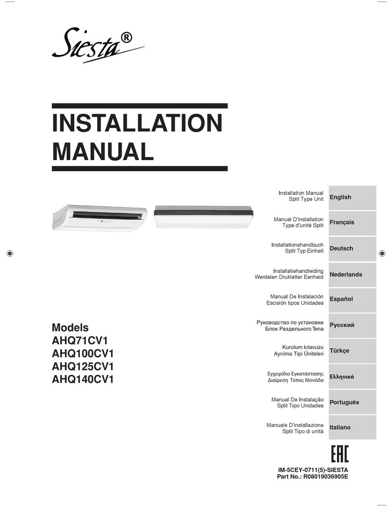
Siesta ATY25FMV1B User manual

INSTALLATION
MANUAL
Models
ATY25FMV1B ARY25FMV1B
ATY35FMV1B ARY35FMV1B
ATY50FMV1B ARY50FMV1B
ATY60FMV1B ARY60FMV1B
ATY71FMV1B ARY71FMV1B
ATYN25FMV1B ARYN25FMV1B
ATYN35FMV1B ARYN35FMV1B
ATYN50FMV1B ARYN50FMV1B
ATYN60FMV1B ARYN60FMV1B
English
Deutsch
Français
Nederlands
Español
Italiano
Ελληνικά
Portugues
Русский
Türkçe
Installation Manual
Split Type Unit
Installationshandbuch
Anlage Mit Getrenntem System
Manuel d’installation
Unité De Type Split
Installatiehandboek
Apparaat Met Gescheiden Systeem
Manual de instalación
Unidad De Tipo Dividido
Manuale Di Installazione
Unità Tipo Split
Εγχειρίδιο εγκατάστασης
Mονάδα διαχωριστικού τύπου
Manual De Instalação
Unidade De Tipo Separado
Руководство По Установке
Блок Раздельного Типа
Kurulum Kılavuzu
Split Tip Ünite

1
English
OUTLINE AND DIMENSIONS
All dimensions are in mm/ (in)
FRONT VIEW
TOP VIEW
A
C
DG F
SIDE VIEW
INSTALLATION
PLATE
ON
I
M
B
EH
I
JKL
Dimension A B C D E
ATY50FMV1B / ATYN50FMV1B 1060 310 220 912 294
ATY60FMV1B / ATYN60FMV1B (41.7) (12.2) (8.6) (35.9) (11.6)
FRONT VIEW
TOP VIEW
INSTALLATION
PLATE
IO
N
SIDE VIEW
C
A
D
CENTER LINE
F
B
G
H
B
M
I
K
L
J
A
Indoor Unit
Dimension K L M N O
ATY50FMV1B / ATYN50FMV1B 354 403 160 138 160
ATY60FMV1B / ATYN60FMV1B (13.9) (15.9) (6.3) (5.4) (6.3)
M
Dimension K L M N O
ATY25FMV1B / 319 379 50 128 132
ATYN25FMV1B (12.6) (15.0) (2.0) (5.1) (5.2)
ATY35FMV1B / 419 495 50 128 132
ATYN35FMV1B (16.5) (19.5) (2.0) (5.1) (5.2)
Dimension F G H I J
ATY25FMV1B / 185 124 8 56 50
ATYN25FMV1B (7.3) (4.9) (0.3) (2.2) (2.0)
ATY35FMV1B / 185 124 8 56 50
ATYN35FMV1B (7.3) (4.9) (0.3) (2.2) (2.0)
Dimension A B C D E
ATY25FMV1B / 799 260 198 379 246
ATYN25FMV1B (31.5) (10.2) (7.8) (15.0) (9.7)
ATY35FMV1B / 899 260 198 590 246
ATYN35FMV1B (35.4) (10.2) (7.8) (23.2) (9.7)
Dimension A B C D E
ATY71FMV1B 1200 (44.1) 360 (14.2) 200 (7.9) 730 (28.7) 347 (13.7)
D
INSTALLATION PLATE
E
FRONT VIEW
TOP VIEW
A
B
C
SIDE VIEW
All dimensions are in mm/ (in)
All dimensions are in mm/ (in)
Dimension F G H I J
ATY50FMV1B / ATYN50FMV1B 99 51 8 48 43
ATY60FMV1B / ATYN60FMV1B (3.9) (2.0) (0.3) (1.9) (1.7)

2
Dimension A B C D E F G H I J K L M N O
ARY50FMV1B / 855 628 328 513 182 44 93 149 101 113 603 126 164 17 49
ARYN50FMV1B (33.7) (24.7) (12.9) (20.0) (7.1) (1.7) (3.7) (5.9) (4.0) (4.4) (23.7) (5.0) (6.4) (0.7) (1.9)
ARY60FMV1B / 855 730 328 513 182 44 93 149 101 113 603 126 164 17 47
ARYN60FMV1B (33.7) (28.7) (12.9) (20.2) (7.2) (1.7) (3.7) (5.9) (4.0) (4.4) (23.7) (5.0) (6.4) (0.7) (1.9)
ARY71FMV1B
All dimensions are in mm/ (in)
All dimensions are in mm/ (in)
30
(1.2)
19
(0.7)
65
(2.6)
80
(3.1)
LKL
NC
M
N
D
A
O
B
EF
C
GH
IJ
Dimension A B C
ARY25FMV1B / 600 475 245
ARYN25FMV1B (23.6) (18.7) (9.6)
ARY35FMV1B / 700 521 250
ARYN35FMV1B (27.5) (20.5) (9.8)
Dimension G H I
ARY25FMV1B / 93 81 83
ARYN25FMV1B (3.6) (3.1) (3.2)
ARY35FMV1B / 95 93 86
ARYN35FMV1B (3.7) (3.6) (3.3)
Dimension J K L
ARY25FMV1B / 55 398 101
ARYN25FMV1B (2.2) (15.6) (3.9)
ARY35FMV1B / 68 441 130
ARYN35FMV1B (2.6) (17.3) (5.1)
Dimension M N O
ARY25FMV1B / 97 17 22
ARYN25FMV1B (3.8) (0.6) (0.8)
ARY35FMV1B / 111 15 18
ARYN35FMV1B (4.3) (0.5) (0.7)
Dimension D E F
ARY25FMV1B / 418 177 35
ARYN25FMV1B (16.4) (6.9) (1.3)
ARY35FMV1B / 485 175 36
ARYN35FMV1B (19.1) (6.8) (1.4)
3
(0.1)
Outdoor Unit
Dimension P Q R S T
ARY50FMV1B / 32 3 23 73 75
ARYN50FMV1B (1.3) (0.1) (0.9) (2.9) (3.0)
ARY60FMV1B / 32 3 23 73 75
ARYN60FMV1B (1.3) (0.1) (0.9) (2.9) (3.0)
ARY71FMV1B
KL
C
M
N
A
D
N
P
FE
C
GH
BQ
R
O
L
ST
IJ
FOR ARY60FMV1B /
ARYN60FMV1B
ONLY

3
English
This manual provides the procedures of installation to ensure a safe and good standard of operation for the air conditioner
unit.
Special adjustment may be necessary to suit local requirements.
Before using your air conditioner, please read this instruction manual carefully and keep it for future reference.
INSTALLATION MANUAL
SAFETY PRECAUTIONS
!CAUTION
Please take note of the following important points when
installing.
• Do not install the unit where leakage of flammable gas
may occur.
If gas leaks and accumulates around the unit, it may
cause fire ignition.
• Ensure that the drainage piping is connected properly.
If the drainage piping is not connected properly, it may
cause water leakage which will dampen the furniture.
• Do not overcharge the unit.
This unit is factory pre-charged. Overcharge will cause
over-current or damage to the compressor.
• Ensure that the units panel is closed after service or
installation.
Unsecured panels will cause the unit to operate noisily.
• Sharp edges and coil surfaces are potential locations which
may cause injury hazards. Avoid from being in contact
with these places.
• Before turning off the power supply, set the remote
controller’s ON/OFF switch to the “OFF” position to
prevent the nuisance tripping of the unit. If this is not done,
the unit’s fans will start turning automatically when power
resumes, posing a hazard to service personnel or the user.
• Do not operate any heating apparatus too close to the air
conditioner unit. This may cause the plastic panel to melt or
deform as a result of the excessive heat.
• Ensure the color of wires of the outdoor unit and the
terminal markings are same to the indoors respectively.
•IMPORTANT : DO NOT INSTALL OR USE THE AIR
CONDITIONER UNIT IN A LAUNDRY ROOM.
!WARNING
• Installation and maintenance should be performed by
qualified persons who are familiar with local code and
regulation, and experienced with this type of appliance.
• All field wiring must be installed in accordance with the
national wiring regulation.
• Ensure that the rated voltage of the unit corresponds to
that of the name plate before commencing wiring work
according to the wiring diagram.
• The unit must be GROUNDED to prevent possible hazard
due to insulation failure.
• All electrical wiring must not touch the refrigerant piping
or any moving parts of the fan motors.
• Confirm that the unit has been switched OFF before
installing or servicing the unit.
• Disconnect from the main power supply before servicing
the air conditioner unit.
• DO NOT pull out the power cord when the power is ON.
This may cause serious electrical shocks which may result
in the fire hazards.
• Keep the indoor and outdoor units, power cable and
transmission wiring, at least 1 m from TVs and radios, to
prevent distorted pictures and static. {Depending on the
type and source of the electrical waves, static may be heard
even when more than 1 m away}
INSTALLATION OF THE OUTDOOR UNIT
The outdoor unit must be installed in such a way, so as to prevent short circuit of
the hot discharged air or obstruction to the smooth air flow. Please follow the
installation clearances shown in the figure. Select the coolest possible place where
intake air temperature is not greater than the outside air temperature (maximum
45°C).
Dimension A B C D
Minimum Distance, 300 1000 300 500
mm (in) (11.8) (39.4) (11.8) (19.7)
Installation Clearances
Note: If there is any obstacle higher than 2m, or if there is any obstruction at
the upper part of the unit, please allow more space than the figure indicated in
the above table.
Obstacle
Return Air
Discharge Air
Obstacle
AB
CD
Obstacle
Return Air
Service
Access
Obstacle
Disposal requirements
Your air conditioning product is marked with this
symbol. This means that electrical and electronic
products shall not be mixed with unsorted household
waste.
Do not try to dismantle the system yourself: the dismantling of
the air conditioning system, treatment of the refrigerant, of oil
and of other parts must be done by a qualified installer in
accordance with relevant local and national legislation.
Air conditioners must be treated at a specialized treatment facility
for re-use, recycling and recovery. By ensuring this product is
disposed of correctly, you will help to prevent potential negative
consequences for the environment and human health. Please
contact the installer or local authority for more information.
Batteries must be removed from the remote controller and
disposed of separately in accordance with relevant local and
national legislation.

4
INSTALLATION OF ORIFICE PIPE
Orifice Pipe
1
2
34
1
2
3
4
Outdoor Unit Indoor
Orifice
Pipe, connecting
Flare nut 3/8" (Female)
Flare joint 3/8" (Male)
!CAUTION
The orifice pipe must be installed in the correct direction as shown above.
Improper direction may cause failure to the operating system.
Note: This installation is only for ATY71FMV1B / ARY71FMV1B
A. Outdoor Unit Orifice Pipe Installation (where installation space is wide enough)
Orifice Pipe
Step 2
Step 1
Steps:
1. Directly connect the “Female” nut of the orifice pipe to
the liquid valve.
2. Flare the liquid pipe and connect it to the “Male” joint
of the orifice pipe.
Orifice Pipe
Liquid Pipe

5
English
Liquid Pipe
Brazer
C. Indoor Unit Orifice Pipe Installation
Indoor Unit
Orifice Pipe
B. Outdoor Unit Orifice Pipe Installation (where installation space is limited)
Step 4
Step 3
Step 2
Step 1
Orifice Pipe
If the orifice pipe cannot be connected directly to the liquid valve due to space constraint, it can be connected in between of the
liquid pipe.
Steps:
1. Flare the liquid pipe and connect it to the liquid valve.
2. Braze an additional “Male” joint to the liquid pipe.
3. Connect the “Female” nut of the Orifice pipe to
the“Male” joint.
4. Flare another liquid pipe and connect it to the “Male”
joint of the orifice pipe.
Liquid Pipe Orifice Pipe
Liquid Pipe
Orifice Pipe
3. Flare another liquid pipe and
connect it to the “Male” joint
of the orifice pipe.
Liquid Pipe
Orifice Pipe
2. Connect the “Female” nut of the
Orifice pipe to the“Male” joint.
Liquid Pipe Orifice Pipe
Steps:
1. Braze an additional “Male” joint
to the liquid pipe.
Liquid Pipe
Brazer

6
INSTALLATION OF THE INDOOR UNIT
The indoor unit must be installed in such a way so as to prevent short circuit of
the cool discharged air with the hot return air. Please follow the installation
clearance shown in the figure. Do not place the indoor unit where there could be
direct sunlight shining on it. Also, this location must be suitable for piping and
drainage, and be away from doors or windows.
Maintenance &
Servicing Space
Air Flow
Direction
Higher
Than
Eye Level
50.0 mm 50.0 mm
Routing Of Piping
Remove the screw holding the front panel.
The refrigerant piping can be routed to the unit in a number of
ways (left or right from the back of the unit), by using the
cut-out holes on the casing of the unit (see figure). Bend the
pipes carefully to the required position in order to align it with
the holes. For the right hand and rear side out, hold the bottom
of the piping and then position it to the required direction (see
figure). The condensation drain hose can be taped to the pipes.
1
23
4
5
Piping Routing
Right & Rear Side Routing
Unit Piping
Drain Hose Fix With Vinyl Tape
Mount The Unit Onto The Installation Plate
Hook the indoor unit onto the upper portion of the
installation plate (Engage the two hooks at the rear top of the
indoor unit with the upper edge of the installation plate). Ensure
that the hooks are properly seated on the installation plate by
moving it to the left and right.
Water Drainage Piping
The indoor drain pipe must be in a downward gradient for smooth
drainage. Avoid situations that are likely to cause water to leak.
Correct
End
Dipped
Into
Water
Water
Leaking
Water
Leaking Water
Leaking
Wrong Wrong Wrong
Drain
Water Drainage
1. Hook the unit onto the installation plate.
Mounting Installation Plate
Ensure that the wall is strong enough to withstand the weight of the unit. Otherwise, it is necessary to reinforce the wall with
plates, beams or pillars.
Use the level gauge for horizontal mounting, and fix it with 4 suitable screws.
In case the rear piping draws out, drill a hole 65mm in diameter with a cone drill, slightly lower on the outside wall (see figure).
Screw Position In The Wall
72.0
Centre Line
Ø 65.0 mm Hole In The Wall
Screw Position In The Wall
Ø 65.0 mm Hole In The Wall
Inside Outside
1/50 Inclination
Hole With Cone Drill
Indoor Side Outdoor Side
Water
Retention

7
English
Piping Length & Elevation
If the pipe is too long, both the capacity and reliability of the unit will
drop. As the number of bends increases, resistance to the flow of
refrigerant system increases, thus lowering cooling capacity. As a
result, the compressor may become defective. Always choose the
shortest path and follow the recommendations as tabulated below:
REFRIGERANT PIPING WORK
Outdoor Unit
Indoor Unit
Piping Works
• Do not use contaminated or damaged copper tubing. Do not
remove plastic, rubber plugs and brass nuts from the valves,
fittings, tubings and coils until you are ready to connect suction
or liquid line into valves or fittings.
• If any brazing work is required, ensure that the nitrogen gas is
passed through coil and joints while the brazing work is being
done. This will eliminate soot formation on the inside walls of
the copper tubings.
• Cut the connection pipe with a pipe cutter.
• Remove burrs from cut edges of the pipes with remover.
Hold the end of the pipe downwards to prevent metal chips from
entering the pipe.
• Insert the flare nuts, mounted on the connection parts of both the
indoor unit and outdoor unit onto the copper pipes.
• Flare the pipe with extra length above the flaring tool as shown
in the table.
• The flared edge must be even and not cracked or scratched.
1/4t
Cutting Copper Tube
Remove Burr
Copper Tube
Swaging
Block
Remark: The refrigerant pre-charged in the outdoor unit is for piping length up to 7.6 m/ 25 ft.
Model ATY25FMV1B ATY35FMV1B ATY50FMV1B ATY60FMV1B ATY71FMV1B
ATYN25FMV1B ATYN35FMV1B ATYN50FMV1B ATYN60FMV1B
Maximum length, m (ft), L 12 (39) 12 (39) 15 (49) 15 (49) 35 (114.8)
Max. elevation, m (ft), H 5 (16.4) 5 (16.4) 8 (26.2) 8 (26.2) 15 (49.2)
Max. number of (90°) bends 10 10 10 10 10
Liquid pipe size 1/4" 1/4" 1/4" 3/8" 3/8"
Gas pipe size 3/8" 1/2" 5/8" 5/8" 5/8"
Ø Tube, D A (mm)
Inch mm Imperial Rigid
1/4" 6.35 1.3 0.7
3/8" 9.52 1.6 1.0
1/2" 12.70 1.9 1.3
5/8" 15.88 2.2 1.7
3/4" 19.05 2.5 2.0

8
COMP
N2
OF
4WV
N1
L
COMP
OF
4WV
N
ELECTRICAL WIRING CONNECTION
Cooling Unit
IMPORTANT: * The figures shown in the table are for information purpose only. They should be checked and selected to
comply with the local/national codes of regulations. This is also subject to the type of installation and conductors
used.
Piping Connection To The Units
• Align the center of the piping and tighten the flare nut
sufficiently with fingers.
• Finally, tighten the flare nut with the torque wrench until the
wrench clicks.
Indoor Piping Flare Nut
Flared TubeFlare Joint
Pipe Size mm / (in) Torque Nm / (ft - lb)
6.35 (1/4) 18 (13.3)
9.53 (3/8) 42 (31.0)
12.7 (1/2) 55 (40.6)
15.88 (5/8) 65 (48.0)
19.05 (3/4) 78 (57.6)
Spanar Torque Wrench
ATY25FMV1B / ATY50FMV1B /
Model ATYN25FMV1B ATYN50FMV1B
ATY35FMV1B / ATY60FMV1B /
ATYN35FMV1B ATYN60FMV1B
Voltage range** 220V-240V / 1Ph / 50Hz + !
Power supply cable size* mm
2
1.5 2.5
Number of wires 33
Interconnection cable size* mm
2
1.5 2.5
Number of wires 55
Recommended fuse A 15 20
!There must be a double pole switch
with a minimum 3mm contact gap and
fuse/circuit breaker as recommended
in the fixed installation circuit.
Outdoor Unit
Terminal Block
Indoor Unit
Terminal Block
Power Supply Cable
Outdoor coil sensor connection wire
(8m long) attached in the indoor unit
Heat Pump Unit (single phase)
Model ATY71FMV1B
Voltage range** 220V-240V / 1Ph / 50Hz + !
Power supply cable size* mm
2
2.5
Number of wires 3
Interconnection cable size* mm
2
2.5
Number of wires 5
Recommended fuse A 20
4WV
OF
COMP
N2
N1
L
4WV
OF
COMP
N
There must be a double pole switch
with a minimum 3mm contact gap and
fuse/circuit breaker as recommended
in the fixed installation circuit.
!
Indoor Unit
Terminal Block
Outdoor Unit
Terminal Block
Power Supply Cable
Outdoor Coil Sensor Connection Wire
(8m long) attached in the indoor unit

9
English
Indoor ATY25FMV1B ATY35FMV1B ATY50FMV1B ATY60FMV1B ATY71FMV1B
Outdoor ARY25FMV1B ARY35FMV1B ARY50FMV1B ARY60FMV1B ARY71FMV1B
Additional Charge [g/m] 23 23 22 56 56
Additional Charge
The refrigerant is pre-charged in the outdoor unit. If the piping length is less than 7.6m (25ft), then additional charge after vacuuming is not
necessary. If the piping length is more than 7.6m (25ft), then use the additional charge valve as indicated in the table.
Charge Operation
This operation must be done by using a gas cylinder and a precise
weighing machine. The additional charge is topped-up into the outdoor
unit using the suction valve via the service port.
• Remove the service port cap.
• Connect the low pressure side of the charging gauge to the suction
service port center of the cylinder tank and close the high pressure
side of the gauge. Purge the air from the service hose.
• Start the air conditioner unit.
• Open the gas cylinder and low pressure charging valve.
• When the required refrigerant quantity is pumped into the unit, close
the low pressure side and the gas cylinder valve.
• Disconnect the service hose from service port. Put back the service
port cap.
Additional refrigerant charge [g] per additional 1m length as tabulated for R22 models.
Purging The Piping And The Indoor Unit
Except for the outdoor unit which is pre-charged with refrigerant, the indoor
unit and the refrigerant connection pipes must be air-purged because the air
containing moisture that remains in the refrigerant cycle may cause malfunc-
tion of the compressor.
• Remove the caps from the valve and the service port.
• Connect the center of the charging gauge to the vacuum pump.
• Connect the charging gauge to the service port of the 3-way valve.
• Start the vacuum pump. Evacuate for approximately 30 minutes. The
evacuation time varies with different vacuum pump capacity. Confirm that
the charging gauge needle has moved towards -760mmHg.
Caution:
• If the gauge needle does not move to -760mmHg, be sure to check for gas
leaks (using the refrigerant detector) at flare type connection of the indoor
and outdoor unit and repair the leak before proceeding to the next step.
• Close the valve of the charging gauge and stop the vacuum pump.
• On the outdoor unit, open the suction valve (3 way) and liquid valve (2 way)
(in anti- clockwise direction) with 4mm key for hexagon sacked screw.
Refrigerant Piping
Service Port Outdoor Unit 3 Ways Valve
Flare Nut
Allen Key
Liquid Side
Indoor Unit Outdoor Unit
Gas Side
Vacuum
Pump
Open
Close
Hi
VACUUMING AND CHARGING
Indoor Unit Liquid Side Outdoor Unit
Gas Side
Check
Valve
Low Close
Hi
• All wires must be firmly connected.
• All wires must not touch the refrigerant piping, compressor
or any moving parts of the fan motor.
• The connecting wires between the indoor unit and the
outdoor unit must be clamped on the wire clamps as shown
in the figure.
• The power supply cord must be equivalent to H05VV-F
(60227 IEC 52 or 60227 IEC 53) which is the minimum
requirement, and to be used in protective tube.
Wire Clamp
Interconnection
Cable
Power Supply
Cable
Indoor ATYN25FMV1B ATYN35FMV1B ATYN50FMV1B ATYN60FMV1B
Outdoor ARYN25FMV1B ARYN35FMV1B ARYN50FMV1B ARYN60FMV1B
Additioal Charge [g/m] 16 16 14 36
Additional refrigerant charge [g] per additional 1m length as tabulated for R410 models.
E.g.
ATYN25FMV1B & ARY25FMV1B with 12m piping length, additional piping length is 4.4m. Thus,
Additional charge = 4.4[m] * 23 [g/m]
= 101.2[g]
Close
Close
Discharge Valve
Suction Valve
Low
Open
Open
Discharge Valve
Suction Valve

10
IR Signal Receiver
When an infrared remote control operating signal has been
transmitted, the signal receiver on the indoor unit will make a
<beep> sound to confirm acceptance of the signal transmission.
Cooling Unit / Heat Pump Unit
The table shows the LED indicator lights for the air conditioner
unit under normal operation and fault conditions.
The LED indicator lights are located at the middle of the air
conditioner unit.
The heat pump units are equipped with an “auto” mode sensor
whereby it will provide reasonable room temperature by switching
automatically to either “cool” or “heat” mode according to the
temperature set by the user.
INDICATOR LIGHTS
LED Indicator Lights for Cooling Unit / Heat Pump Unit
LED Indicator Lights
IR Receiver
Sleep mode Cool Timer Ionizer
LED Indicator Lights : Normal Operation And Fault Conditions For Cooling / Heat Pump Unit
Normal Operation / Fault Indication Action
Cool mode –
Heat mode –
Auto mode in Heating operation –
Auto mode in Cooling operation –
Timer on –
Sleep mode on –
Ionizer on –
Fan mode on –
Dry mode on –
Room air sensor contact
Loose / Short Call your dealer
Outdoor coil sensor open Call your dealer
Indoor coil sensor open Call your dealer
Compressor overload /
Indoor coil sensor short / Call your dealer
outdoor coil sensor short
Defrost operation –
Gas leak Call your dealer
Outdoor coil sensor exist (MS Model) Call your dealer
Hardware error (tact switch pin short) Call your dealer
6 times
1 time
COOL/HEAT
(GREEN/RED)
Red
Green
Red
Green
Red
ON ON or OFF Blinking
1 time
3 times
3 times
5 times

11
English
LED Indicator Lights : Normal Operation And Fault Conditions For Heat Pump Unit
If the system is in cool mode or heat mode (with the sleep function off), the sensor
may have a contact problem, compressor overload protection trip or gas leak.
Normal Operation/Fault Condition Action
Cool Dry Fan Heat Sleep
Heat Pump Unit
The table shows the LED indicator lights for the air conditioner
unit under normal operation and fault conditions.
The LED indicator lights are located at the bottom right side of
the air conditioner unit.
The heat pump units are equipped with an “auto” mode sensor
whereby it will provide reasonable room temperature by
switching automatically to either “cool” or “heat” mode,
according to the temperature set by the user.
LED Indicator Lights For Heat Pump Unit
Cooling mode Dry mode Heat/Fan mode Sleep mode
(red/green)
ON or OFF
ON Blinking
Cooling mode. –
Dry mode. –
Fan mode. –
Heat mode. –
Auto mode in heating operation. –
Auto mode in cooling operation. –
Defrost operation. –
Compressor overload protection. Call your dealer.
Indoor coil sensor contact loose/short. Call your dealer.
Outdoor coil sensor contact loose/short. Call your dealer.
Room air sensor contact loose/short. Call your dealer.

12
HOT KEEP
OFF
ON
MS
ON/OFF
ON/OFF switch
AIR CONDITIONER UNIT OPERATION
Dry Mode
• When the air humidity is high, the unit can operate in dry
mode. Press <MODE> button and choose <DRY>.
• If the room temperature is 2°C/3.6°F higher than the set
temperature, the air conditioner will operate under
cooling mode until it reaches within the 2°C/3.6°F range
of difference compared to the set temperature before it
converts to dry mode.
• If the room temperature is within the 2°C/3.6°F range of
difference compared to the set temperature, it will
directly operate under dry mode.
• The unit will operate at LOW speed under dry mode.
Heat Mode (for heat pump unit only)
• When the unit is switched on from cold start or
defrosting cycle, the indoor fan will start to operate only
after the coil reaches the desired temperature.
• When the set temperature is achieved, the indoor fan will
operate until the coil cannot provide anymore
additional heat.
Horizontal Air Flow Control
• For more effective air circulation, you can manually
adjust the air discharge grille to the left or right.
• During cool mode operation and dry mode operation, do
not direct the air discharge louver downwards for too long.
If operating continues in this way, condensation may
occur on the louver, thus resulting in drippings.
Hot Keep (for heat pump only)
• During compressor cut off, the indoor fan can be switched
to
(i) ON (default) or
(ii) OFF or
(iii) Interval on and off
by setting the slide switch shown in the diagram.
• The switch is located at the front frame cover (next to the
ON/OFF switch).
Note : When the option is selected, the power supply of the
unit needs to be reset in order to activate the
function.
Multi-Split (for heat pump only)
• The unit can be switched to multi split (MS) by setting the
slide switch shown in the diagram.
• For hot keep, during compressor cut off, the indoor fan
motor will switch to OFF by default.
Note : When the option is selected, the power supply of the
unit needs to be reset in order to activate the
function.
Overheating Protection (for heat pump unit only)
• In case the internal and/or the external temperature is to
high, or that the filter is dirty and clogged up, the
refrigerant may be overheated. The compressor will cut
out when the condensing temperature reaches 62°C/
143.6°F.
Frost Prevention
• When the air filter is dirty, the evaporating temperature
will decrease and eventually cause frosting.
• The LED light will blink to indicate that the filter is dirty.
If the evaporating temperature reaches -1°C/33.8°F, the
unit will trip and defrost.
Horizontal
Dry
25˚C / 77˚F

13
English
INSTALLATION OF UNIT WITH O2THERAPY FEATURE
3. Insert the end hose to the connector (indoor)
Refrigerant Piping
2. Insert the end hose to the connector (outdoor)
1. Open valve cover to connecting the
O2hose
O2Hose
If there is a power cut when the unit is operating, it will automatically resume the same operating mode when the power is
restored.
!CAUTION
Before turning off the power supply, set the remote controller’s ON/OFF switch to the “OFF” position to prevent the nuisance
tripping of the unit.
If this is not done, the unit’s fans will start turning automatically when power resumes, posing a hazard to service personnel or the
user.
AUTO RANDOM RE-START FUNCTION
!CAUTION
1. The electrostatic air purifying and deodorizing filter should be replaced once every 6 months or when the
filter changes color to brownish, whichever is sooner.
2. Used dusty filters should be disposed and shouldn't be reused, even if it has been cleaned and washed.
3. The filter is a consumable part which you can purchase from your air conditioner dealer.
4. Use the new filter immediately once it has been taken out from its sealed packing. Do not unpack the new filter too early before
it is actually used as this may decrease its deodorizing effect.
Heat Pump Unit
Temperature Ts °C / °F Th °C / °F
Minimum indoor temperature 16.0 / 60.8 –
Maximum indoor temperature 30.0 / 86.0 –
Minimum outdoor temperature -8.0 / 17.6 -9.0 / 15.8
Maximum outdoor temperature 24.0 / 75.2 18.0 / 64.4
Ts: Dry bulb temperature. Th: Wet bulb temperature.
STANDARD OPERATING CONDITIONS

14
!CAUTION
Do not operate any heating apparatus too close to the air conditioner unit. This may cause the plastic panel to melt or deform as
a result of the excessive heat.
1Off the unit.
2Unscrew the air discharge housing.
3Flip open the air discharge housing.
4Clean the blower.
5Close the air discharge housing and tighten it with screw.
When The Unit Is Not To Be Used For An Extended Long Period Of Time
Remove the power plug.
If you are using an independent
electric circuit for your unit,
cut off the circuit.
Remove the batteries in the
remote control.
Operate the unit for 2 hours
with the following setting.
Operating mode : cool
Temperature : 30°C/86°F
Maintenance Procedures
1. Remove any dust adhering to the filter by using a vacuum cleaner or wash in
lukewarm water (below 40°C/104°F) with a neutral cleaning detergent.
2. Rinse the filter well and dry before placing it back onto the unit.
3. Do not use gasoline, volatile substances or chemicals to clean the filter.
1. Clean any dirt or dust on the grille or panel by wiping it with a soft cloth
soaked in lukewarm water (below 40°C/104°F) and a neutral detergent
solution.
2. Do not use gasoline, volatile substances or chemicals to clean the
indoor unit.
Period
At least once
every 2 weeks.
More frequently if
necessary.
At least once
every 2 weeks.
More frequently if
necessary.
Service Parts
Indoor air filter
Indoor unit
SERVICE AND MAINTENANCE
!WARNING
•Disconnect from the main power supply before servicing the air conditioner unit.
•DO NOT pull out the power cord when the power is ON. This may cause serious electrical shocks which may result
in fire hazards.

15
English
If any malfunction of the air conditioner unit is noted, immediately switch off the power supply to the unit. Check the
following fault conditions and causes for some simple troubleshooting tips.
If the fault persists, please call your local dealer / serviceman.
TROUBLESHOOTING
Causes / Action
- Protection against frequent starting. Wait for 3 to 4 minutes for the
compressor to start operating.
- Power failure, or the fuse needs to be replaced.
- The power plug is disconnected.
- It is possible that your delay timer has been set incorrectly.
- If the fault persist after all these verifications, please
contact the air conditioner unit installer.
- The air filter is dirty.
- The doors or windows are open.
- The air suction and discharge are clogged.
- The regulated temperature is not high enough.
- Odoors may be caused by cigarettes, smoke particles, perfume etc.
which might have adhered onto the coil.
- This is caused by air humidity after an extended long period of
operation.
- The set temperature is too low, increase the temperature setting and
operate the unit at high fan speed.
- Switch off unit and call dealer.
- Refrigerant fluid flowing into the evaporator coil.
Fault
1. The compressor does not operate 3 minutes after the air
conditioner unit is started.
2. The air conditioner unit does not operate.
3. The air flow is too low.
4. Discharge air flow has bad odour.
5. Condensation on the front air grille of the indoor unit.
6. Water flowing out from the air conditioner unit.
7. Hissing air flow sound from the air conditioner unit during
operation.

1
Deutsch
AUSLEGUNG UND ABMESSUNG
Alle abmessungen sind in mm/(in)
VORDERANSICHT
ANSICHT VON OBEN
A
C
DG F
SEITENANSICHT
MONTAGEPLATTE
ON
I
M
B
EH
I
JKL
Abmessung A B C D E
ATY50FMV1B / ATYN50FMV1B 1060 310 220 912 294
ATY60FMV1B / ATYN60FMV1B (41,7) (12,2) (8,6) (35,9) (11,6)
VORDERANSICHT
ANSICHT VON OBEN
MONTAGEPLATTE
IO
N
SEITENANSICHT
C
A
D
MITTELLINIE
F
B
G
H
B
M
I
K
L
J
A
Innen-Gerät
Abmessung K L M N O
ATY50FMV1B / ATYN50FMV1B 354 403 160 138 160
ATY60FMV1B / ATYN60FMV1B (13,9) (15,9) (6,3) (5,4) (6,3)
M
Abmessung K L M N O
ATY25FMV1B / 319 379 50 128 132
ATYN25FMV1B (12,6) (15,0) (2,0) (5,1) (5,2)
ATY35FMV1B / 419 495 50 128 132
ATYN35FMV1B (16,5) (19,5) (2,0) (5,1) (5,2)
Abmessung F G H I J
ATY25FMV1B / 185 124 8 56 50
ATYN25FMV1B (7,3) (4,9) (0,3) (2,2) (2,0)
ATY35FMV1B / 185 124 8 56 50
ATYN35FMV1B (7,3) (4,9) (0,3) (2,2) (2,0)
Abmessung A B C D E
ATY25FMV1B / 799 260 198 379 246
ATYN25FMV1B (31,5) (10,2) (7,8) (15,0) (9,7)
ATY35FMV1B / 899 260 198 590 246
ATYN35FMV1B (35,4) (10,2) (7,8) (23,2) (9,7)
Abmessung A B C D E
ATY71FMV1B 1200 (44,1) 360 (14,2) 200 (7,9) 730 (28,7) 347 (13,7)
D
MONTAGEPLATTE
E
VORDERANSICHT
ANSICHT VON OBEN
A
B
C
SEITENANSICHT
Alle abmessungen sind in mm/(in)
Alle abmessungen sind in mm/(in)
Abmessung F G H I J
ATY50FMV1B / ATYN50FMV1B 99 51 8 48 43
ATY60FMV1B / ATYN60FMV1B (3,9) (2,0) (0,3) (1,9) (1,7)

2
Abmessung A B C D E F G H I J K L M N O
ARY50FMV1B / 855 628 328 513 182 44 93 149 101 113 603 126 164 17 49
ARYN50FMV1B (33,7) (24,7) (12,9) (20,0) (7,1) (1,7) (3,7) (5,9) (4,0) (4,4) (23,7) (5,0) (6,4) (0,7) (1,9)
ARY60FMV1B / 855 730 328 513 182 44 93 149 101 113 603 126 164 17 47
ARYN60FMV1B (33,7) (28,7) (12,9) (20,2) (7,2) (1,7) (3,7) (5,9) (4,0) (4,4) (23,7) (5,0) (6,4) (0,7) (1,9)
ARY71FMV1B
Alle abmessungen sind in mm/(in)
Alle abmessungen sind in mm/(in)
30
(1,2)
19
(0,7)
65
(2,6)
80
(3,1)
LKL
NC
M
N
D
A
O
B
EF
C
GH
IJ
Abmessung A B C
ARY25FMV1B / 600 475 245
ARYN25FMV1B (23,6) (18,7) (9,6)
ARY35FMV1B / 700 521 250
ARYN35FMV1B (27,5) (20,5) (9,8)
Abmessung G H I
ARY25FMV1B / 93 81 83
ARYN25FMV1B (3,6) (3,1) (3,2)
ARY35FMV1B / 95 93 86
ARYN35FMV1B (3,7) (3,6) (3,3)
Abmessung J K L
ARY25FMV1B / 55 398 101
ARYN25FMV1B (2,2) (15,6) (3,9)
ARY35FMV1B / 68 441 130
ARYN35FMV1B (2,6) (17,3) (5,1)
Abmessung M N O
ARY25FMV1B / 97 17 22
ARYN25FMV1B (3,8) (0,6) (0,8)
ARY35FMV1B / 111 15 18
ARYN35FMV1B (4,3) (0,5) (0,7)
Abmessung D E F
ARY25FMV1B / 418 177 35
ARYN25FMV1B (16,4) (6,9) (1,3)
ARY35FMV1B / 485 175 36
ARYN35FMV1B (19,1) (6,8) (1,4)
3
(0,1)
Außen-Gerät
Abmessung P Q R S T
ARY50FMV1B / 32 3 23 73 75
ARYN50FMV1B (1,3) (0,1) (0,9) (2,9) (3,0)
ARY60FMV1B / 32 3 23 73 75
ARYN60FMV1B (1,3) (0,1) (0,9) (2,9) (3,0)
ARY71FMV1B
KL
C
M
N
A
D
N
P
FE
C
GH
BQ
R
O
L
ST
IJ
NUR FÜR
ARY60FMV1B /
ARYN60FMV1B

3
Deutsch
Das vorliegende Handbuch enthält die Installationsanweisungen für einen sicheren und ordnungsgemäßen Betrieb
dieser Anlage.
Je nach den örtlichen Gegebenheiten können spezielle Anpassungen notwendig sein.
Vor der Inbetriebnahme des Klimagerätes dieses Handbuch bitte aufmerksam zur Kenntnis nehmen und für
künftigen Bedarf aufbewahren.
MONTAGEANLEITUNG
VORSICHTMASSNAHMEN
!VORSICHT
Vor der Installation sind folgende wichtige Punkte zu
prüfen.
• Gerät nicht installieren, falls ein Leck entzündbaren
Gases festgestellt wird.
Es besteht Feuergefahr, wenn Gas aus der Anlage
entweicht und sich in der Umgebung ansammelt.
• Die Kondensat-Abflußleitung muß sachgemäß
angeschlossen sein.
Wenn die Kondensat-Abflussleitung nicht richtig
angeschlossen wird, kann ein Wasserverlust auftreten,
der die Möbel beschädigt.
• Gerät nicht überlasten.
Das Gerät ist werkseitig vorgefüllt. Im Falle einer
Überfüllung besteht die Gefahr einer Überbelastung
oder sonstigen Beschädigung des Kompressors.
• Nach Installation oder Wartung ist sicherzustellen, daß
die Geräteabdeckung wieder montiert ist.
Eine mangelhafte Befestigung der Abdeckung führt zu
Geräuschentwicklung während des Betriebs.
• Scharfe Kanten und Wärmetauscherflächen stellen eine
Gefahrenquelle dar. Jeglicher Kontakt mit diesen Stellen
ist zu vermeiden.
• Vor Abschalten der Stromzufuhr muss der EIN/AUS-
Schalter der Fernbedienung auf “AUS” gestellt werden,
um eine versehentliche Fehleinstellung zu vermeiden.
Andernfalls schaltet sich bei Wiederherstellung der
Stromzufuhr das Kühlgebläse automatisch wieder ein und
kann somit für den Benutzer oder Wartungspersonal ein
unerwartetes Risiko darstellen.
• Keine Heizgeräte zu dicht bei der Klimaanlage
einschalten. Dies kann zur Folge haben, dass die
Kunststoffabdeckung durch zu große Wärme schmilzt oder
beschädigt wird.
• Vergewissern Sie sich, dass die Drahtfarben des
Außengeräts und die Gerätemarkierungen den
Drahtfarben des Innengeräts entsprechen.
•WICHTIG : DAS KLIMAGERÄT SOLLTE NICHT IN
EINER WASCHKÜCHE INSTALLIERT ODER
BENUTZT WERDEN.
!ACHTUNG
• Die Installation und Wartung muß durch qualifizietes
Personal erfolgen, Welches mit den örtlichen Bestimmungen
und diesem Ausrüstungstyp vertraut ist.
• Die gesamte E-Verkabelung hat in Übereinstimmung mit
den landesspezifischen Anschlußvorschriften zu erfolgen.
• Vor dem Kabelanschluß gemäß Schaltbild ist sicherzustellen,
daß die Betriebsspannung mit der auf dem Datenschild des
Gerätes angegebenen Spannung übereinstimmt.
• Das Gerät ist zum Schutz gegen fehlerhafte Isolierungen und
entsprechende Risiken zu ERDEN.
• Die gesamte Verkabelung darf weder die Kühlmittelleitung
noch andere bewegliche Teile desVentilatormotors berühren.
• Vor der Installation oder Wartung der Anlage ist
sicherzustellen, daß das Gerät ausgeschaltet ist (OFF).
•
Vor Wartung des Klimagerätes das Stromkabel vom Netz trennen.
• NICHT das Stromkabel herausziehen, wenn das Gerät noch
eingeschaltet ist. Ein elektrischer Schlag oder ein
Wohnungsbrand kann die Folge sein.
•
Halten Sie die Innen- und Außengeräte, das Stromkabel und die
Verkabelung in einem Mindestabstand von 1m von Fernsehgeräten
und Radios entfernt, um die Wiedergabequalität von Fernsehbildern
nicht zu beeinträchtigen und Interferenzen zu vermeiden.
{Abhängig von der Art und Quelle der elektrischen Wellen, ist
eine Interferenz möglicherweise hörbar, auch wenn das Gerät weiter
als 1m entfernt aufgebaut ist}.
INSTALLATION DES AUßENGERÄTES
Wandelement
Luftzufuhr
Auslassluft
Wandelement
AB
CD
Wandelement
Luftzufuhr
Wartungs-Offnung
Wandelement
Vorschriften zur Entsorgung
Ihre Klimaanlage ist mit diesem Symbol gekennzeichnet.
Das bedeutet, dass elektrische
und elektronische Produkte nicht mit unsortiertem
Haushaltsabfall entsorgt werden dürfen.
Versuchen Sie auf keinen Fall das System selbst zu demontieren. Die
Demontage des Klimaanlagensystems sowie die Handhabung von
Kältemittel, Öl und möglichen weiteren Teilen muss von einem
qualifizierten Monteur gemäß den entsprechenden örtlichen und
staatlichen Bestimmungen vorgenommen werden.
Klimaanlagen müssen bei einer fachkundigen Einrichtung für
Wiederverwendung, Recycling und Wiedergewinnung aufbereitet
werden. Indem Sie dieses Produkt korrekt entsorgen, helfen Sie
potenzielle negative Folgen für die Umwelt und die Gesundheit der
Menschen zu vermeiden. Nehmen Sie bitte hinsichtlich weiterer
Informationen Kontakt auf mit dem Monteur oder den örtlichen
Behörden.
Die Batterien müssen aus der Fernbedienung entfernt werden und
gemäß den entsprechenden örtlichen und staatlichen Vorschriften
separat entsorgt werden.
DieAußenmontage-Einheit ist so zu installieren, daß die Luftzirkulation an keiner
Stelle beeinträchtigt oder durch ein Hindernis am Abströmen gehindert wird.
Auf Einhaltung der nachstehend gezeigten Mindestabstände achten.Auszuwählen
ist die jeweils kühlste Stelle, an der die Einlaßlufttemperatur nicht die
Außentemperatur überschreitet (maximal 45°C).
Abmessung A B C D
Mindest Entfernung, 300 1000 300 500
mm (in) (11,8) (39,4) (11,8) (19,7)
Montageabstand
Anmerkung: Bei einem Hindernis von über 2m oder soweit sich irgendein
Hindernis im oberen Bereich der Einheit befindet, muß der in obenstehender
Tabelle aufgeführte Abstand entsprechend vergrößert werden.

4
INSTALLATION DER ÖFFNUNGSROHRLEITUNG
Ablassrohr
1
2
34
1
2
3
4
Außengerät Innenräume
Ablassstück
Verbindungsrohr
3/8" - Schraubenmutter
3/8" - Sechskanthohlschraube
!VORSIHT
Das Ablassrohr muss, wie oben erläutert, in die richtige Richtung eingebaut werden.
Ein falscher Einbau kann Schäden im Betriebssystem verursachen.
Anmerkung: Dieses Einbauverfahren bezieht sich nur auf die Modelle ATY71FMV1B / ARY71FMV1B
A. Öffnungsrohrleitung des Außengerätes (wo der Installationsraum weit genug ist)
Ablassrohr
Schritte:
1. Verbinden Sie die Schraubenmutter des Ablassrohres
direkt mit dem Flüssigkeitsventil.
2. Bringen Sie das Flüssigkeitsrohr an und verbinden Sie
es mit der Hohlschraube des Auslassrohres.
Ablassrohr
Flüssigkeitsrohr
Schritt 2
Schritt 1
This manual suits for next models
17
Table of contents
Languages:
Other Siesta Air Conditioner manuals
