Sifam Tinsley Insu 5Dx User manual

Insu 5Dx
5KV Digital Insulaon Tester
User Manual

Insu 5Dx
1
Table of contents
1 PRECAUTIONS AND SAFETY MEASURES....................................................................................................2
1.1 Preliminary instrucons ................................................................................................................................ 2
1.2 During use ..................................................................................................................................................... 3
1.3 Aer use ....................................................................................................................................................... 3
1.4 Definion of measurement (overvoltage) category ........................................................................................ 3
2 GENERAL DESCRIPTION ............................................................................................................................4
2.1 Instrument features ...................................................................................................................................... 4
3 PREPARATION FOR USE............................................................................................................................4
3.1 Inial inspecons .......................................................................................................................................... 4
3.2 Power supply ................................................................................................................................................ 4
3.3 Calibraon .................................................................................................................................................... 4
3.4 Storage ......................................................................................................................................................... 4
4 OPERATING INSTRUCTIONS .....................................................................................................................5
4.1 Instrument descripon .................................................................................................................................. 5
4.2 Descripon of funcon keys .......................................................................................................................... 5
4.3 Descripon of display .................................................................................................................................... 6
4.4 Descripon of measuring leads...................................................................................................................... 7
4.5 GUARD lead .................................................................................................................................................. 7
4.6 Notes on the insulaon measurements ......................................................................................................... 7
4.7 Switch on the instrument .............................................................................................................................. 8
4.7.1 Configuraon of the test parameters for FIX mode ............................................................................. 8
4.8 Insulaon measurement in FIX mode ............................................................................................................ 9
4.8.1 Configuraon of the test parameters for FIX mode ............................................................................12
4.9 Insulaon measurement in ADJUST mode ....................................................................................................13
4.9.1 Configuraon of the test parameters for ADJUST mode .....................................................................16
4.10 Insulaon measurement in RAMP mode .......................................................................................................17
4.10.1 Configuraon of the test parameters for RAMP#1 mode ....................................................................21
4.10.2 Configuraon of the test parameters for RAMP#2 mode ....................................................................21
4.10.3 Configuraon of the test parameters for RAMP#3 mode ....................................................................22
4.11 Enable/Disable of SMOOTH funcon ............................................................................................................22
4.12 Anomalous situaons ...................................................................................................................................22
5 MANAGEMENT OF MEMORY DATA ........................................................................................................ 25
5.1 Save measurements .....................................................................................................................................25
5.2 Delete measurements ..................................................................................................................................25
5.3 Recall measurements ...................................................................................................................................26
6 RESET OF INSTRUMENT ......................................................................................................................... 26
7 CONNECTION OF THE INSTRUMENT TO PC............................................................................................. 26
8 MAINTENANCE ...................................................................................................................................... 27
8.1 General informaon .....................................................................................................................................27
8.2 Recharging internal baery ..........................................................................................................................27
8.3 Cleaning the instrument ...............................................................................................................................27
8.4 End of life .....................................................................................................................................................27
9 TECHNICAL SPECIFICATIONS .................................................................................................................. 28
9.1 Reference guidelines ....................................................................................................................................29
9.2 General characteriscs .................................................................................................................................29
9.3 Environment ................................................................................................................................................30
9.4.1. Environmental condions for use ......................................................................................................30
9.4 Accessories ..................................................................................................................................................30
9.4.1 Standard accessories .........................................................................................................................30
9.4.2 Oponal accessories ..........................................................................................................................30
10 SERVICE ................................................................................................................................................. 31
10.1 Service operaon .........................................................................................................................................31
11 THEORETICAL APPENDIX ........................................................................................................................ 32
11.1 Polarizaon Index (PI) ..................................................................................................................................32
11.2 Dielectric Absorbon Rao (DAR) .................................................................................................................32

2
1 PRECAUTIONS AND SAFETY MEASURES
The instrument has been designed in compliance with standards IEC/EN61557 and IEC/EN61010-1
regarding electronic measuring instruments.
CAUTION
For the operator’s safety and to prevent damaging the instrument, follow the
procedures described in this manual and carefully read all notes preceded by the
symbol .
Before and during measurements, carefully observe the following instrucons:
Do not perform any measurement in humid environments, in the presence of gas or explosive
or inflammable material or in dusty areas
Even when no measurements are being performed, avoid any contact with the circuit being
tested, with exposed metal parts, with unused measuring leads or circuits, etc
Do not perform any measurement when anomalies are found in the instrument, such as
deformaons, breaks, substance leaks, no display view, etc
Pay special aenon when measuring voltages above 25V in special environments (building
yards, swimming pools, etc.) and 50V in ordinary environments, as there is the danger of
electric shocks.
In this manual and on the instrument, the following symbols are used:
CAUTION: it is necessary to consult the instrucon manual to find the type of potenal
danger and the acons to be taken.
Observe the instrucons reported in the manual. An improper use could damage the
instrument and lead to dangerous situaons for the operator.
DC voltage or current.
AC voltage or current.
Dangerous voltages: risk of electric shocks.
Instrument with double insulaon.
1.1 PRELIMINARY INSTRUCTIONS
This instrument has been designed for use in an environment with polluon level 2
It may also be used to test industrial electrical systems up to overvoltage category IV 600V to
earth with maximum voltage 600V between inputs
Follow the usual safety rules to protect the operator from dangerous currents and protect the
instrument against improper use
Never use the instrument resng on the floor, it must be placed over flat horizontal surfaces
Only the accessories supplied with the instrument guarantee safety standards. They must be in
good condions and replaced, if necessary, with idencal models
Do not measure systems exceeding the current and voltage limit values specified
Do not perform measurements in environmental condions not within the limit values
indicated in this manual
Before connecng the probes to the circuit to be tested, check that the correct funcon is
selected.
3
1.2 DURING USE
Carefully read the following recommendaons and instrucons:
CAUTION
Failure to observe the cauons and/or instrucons may damage the instrument
and/or its components or generate a danger for the operator. If, during use, the low
baery symbol appears on the display, insert the supply cable into the Mains socket
to start baery recharge. During baery recharge, it is possible to perform
measurements.
Before selecng a new funcon, disconnect the measuring probes from the circuit
When the instrument is connected to the circuit being tested, never touch any unused lead
Avoid measuring resistance with external voltages; even if the instrument is protected, as an
excess voltage may cause instrument malfuncons
Prevent that the instrument receives voltage during measurement (e.g. a probe slipping from
the measuring point and touching a point under voltage)
Avoid inserng the plug of the supply cable into the Mains socket while measuring.
1.3 AFTER USE
When measurements are completed, turn off the instrument by pressing the ON/OFF key.
1.4 DEFINITION OF MEASUREMENT (OVERVOLTAGE) CATEGORY
Standard "IEC/EN61010-1: Safety requirements for electrical equipment for measurement, control
and laboratory use, Part 1: General requirements", defines what is intended for measurement
category, commonly known as overvoltage category. In § 6.7.4: Measuring circuits, it reads:
Circuits are divided into the following measurement categories:
Measurement category IV is for measurements performed at the source of a low-voltage
installaon
Examples are electric counters and measurements on primary devices protecng against
overcurrents and on ripple adjusng units
Measurement category III is for measurements performed on installaons inside buildings
Examples are measurements performed on distribuon boards, circuit breakers, wiring
harnesses, including cables, bars, juncon boxes, switches, sockets of fixed installaons and
appliances designed for industrial use and other equipment, e.g. staonary motors connected
to fixed systems.
Measurement category II is for measurements performed on circuits directly connected to the
low-voltage installaon.
Examples are measurements performed on household appliances, portable tools and similar
equipment.
Measurement category I is for measurements performed on circuits not directly connected to
the MAINS.
Examples are measurements performed on circuits not derived from the MAINS and on circuits
derived from the MAINS provided with a special (internal) protecon. In this laer case, the
stress caused by the transients is variable; therefore, (OMISSIS) it is necessary that the user
knows the appliance’s resistance to transients.
4
2 GENERAL DESCRIPTION
The instrument You purchased, if used in compliance with the indicaons given in this manual,
guarantees accurate and reliable measurements and the utmost safety thanks to a development
of new concepon which ensures double insulaon and, consequently, compliance with the
requirements of overvoltage category IV.
2.1 INSTRUMENT FEATURES
Insulaon resistance measurement with nominal voltage which can be set up to 5kV
Dielectric leakage current measurement
Polarizaon Index (PI) measurement
Dielectric Absorpon Rao (DAR) measurement
Capacitance measurement.
AC/DC voltage measurement up to 600V
3 PREPARATION FOR USE
3.1 INITIAL INSPECTIONS
Before shipment, the instrument’s electronics and mechanics have been inspected. All possible
precauons have been taken in order for the instrument to be delivered without damage.
However, we recommend generally inspecng the instrument in order to detect any damage
suffered during transport. Should you detect any anomalies, immediately contact the forwarding
agent or the dealer.
Moreover, we recommend checking that the package contains all parts listed in § 9.4. Should you
find any discrepancy, please contact the dealer. Should it become necessary to return the
instrument, please follow the instrucons reported in § 10
3.2 POWER SUPPLY
The instrument is power-supplied through internal baeries which are recharged from the mains
by means of a baery charger integrated in the instrument itself. The symbol “ ” steadily
illuminated in the right boom part indicates that the baeries are flat and must be recharged . To
recharge the baeries, follow the instrucons given in § 8.2
CAUTION
Perform at least a complete recharging of internal baery in one year. If the
instrument is not used for one year, the baery can be damaged and could not be
completely recharging neither aer some charging/discharging cycles.
3.3 CALIBRATION
The instrument complies with the technical specifications reported in this manual. Its correct
operaon is guaranteed for one year from the date of purchase.
3.4 STORAGE
In order to guarantee accurate measurements and protect the instrument from possible failures,
aer a long storage period under extreme environmental condions, wait for the instrument to
return to a normal condion (see § 9.4.1).

5
4 OPERATING INSTRUCTIONS
4.1 INSTRUMENT DESCRIPTION
CAPTION:
1. Input bushings
2. Mains socket
3. RS232 connector
4. ON/OFF/ key
5. Mulfuncon arrow keys
6. FUNC/ERASE MEM key
7. MODE/CLEAR SMOOTH key
8. SET/DISPLAY MEM key
9. ESC/RECALL MEM key
10. SAVE key
11. START/STOP key
12. LCD display
Fig. 1: Instrument descripon
4.2 DESCRIPTION OF FUNCTION KEYS
Key Descripon
Mulfuncon arrow keys they have several funcons which are
described in detail below
ON/OFF/ key used for:
Switch on/off the instrument
Switch on the display’s backlighng for 20 seconds (short
pressing of the key with the instrument already on)
FUNC/ERASE MEM key used for:
Select the desired funcon
Delete the measurements saved during the display of memory
data
MODE/CLEAR SMOOTH key used for:
Change the internal modes (if there are more available modes)
The pressure of the key set the default value of the selected
parameter
SET/DISPLAY MEM key used for:
Set the test parameters of a funcon
The pressure of the key shows the dates of the measurement
saved inside the memory

6
ESC/RECALL MEM key used for:
Access to the data saved in the memory (if present)
From a parameter seng screen or memory data display screen,
pressing the key once allows returning to the previous screen
SAVE key used for:
Once a measurement has been completed, pressing the key once
allows saving the results in the memory
From a parameter seng screen, pressing the key once allows
saving the changes made to the parameters
START/STOP key used for:
Start and/or stop a measurement
Table 1: Descripon of funcon keys
4.3 DESCRIPTION OF DISPLAY
Symbol Descripon
Display group 1 shows:
Insulaon resistance
Dielectric leakage current
PI (Polarizaon Index)
DAR (Dielectric Absorpon Rao)
Capacitance
Display group 2 shows:
Nominal test voltage
Generated test voltage
Display group 3 shows the duraon me of the test
Bargraph
Modes available test : FIX, ADJUST and RAMP
, , “Flash”, Alarm (values over limits), “Warning” symbols
, , “Low baery", “Mains supply", “Timer” symbols
“Number of test cycles” symbol
Table 2: Descripon of symbols of display
7
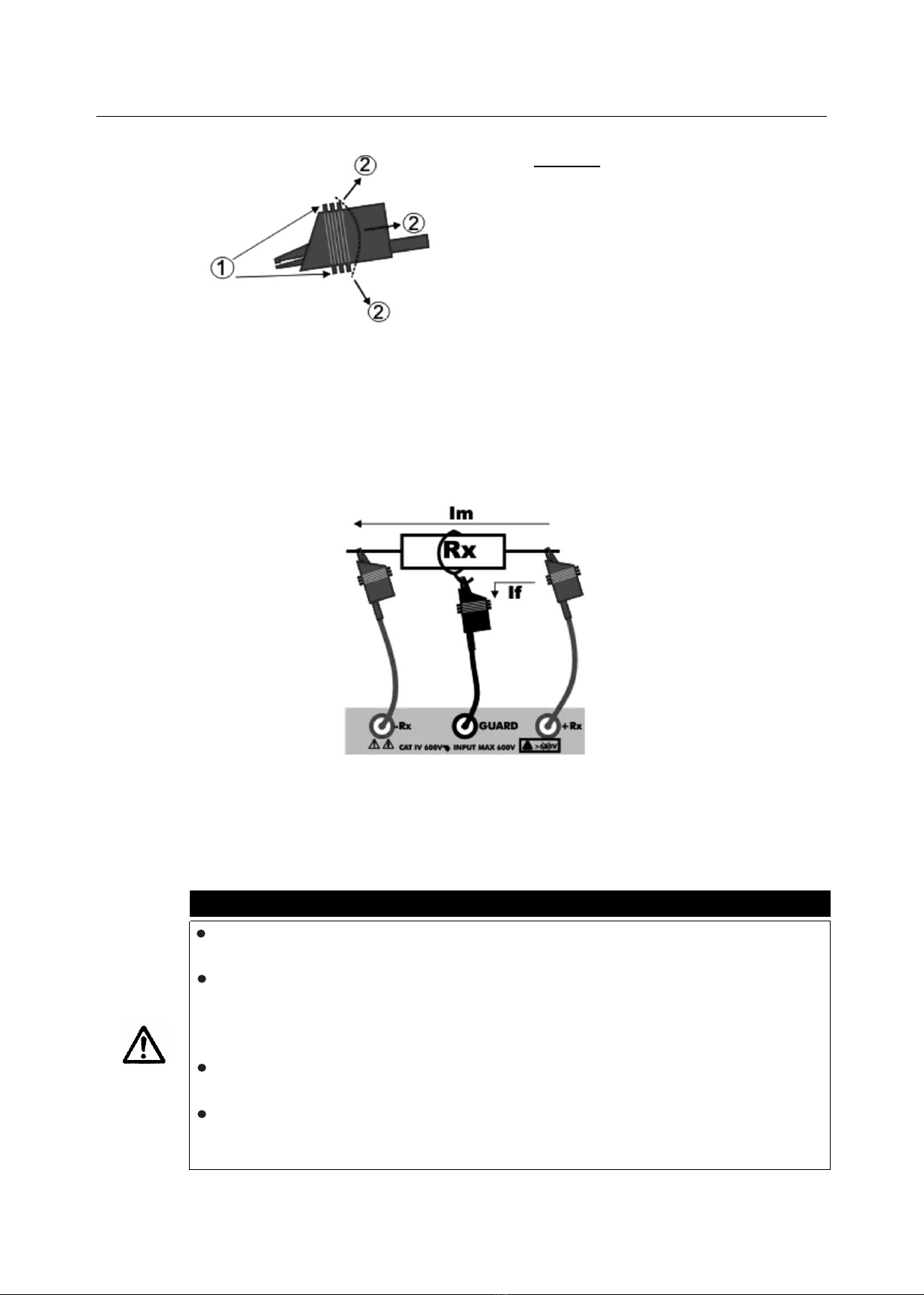
4.4 DESCRIPTION OF MEASURING LEADS
CAPTION:
1. Hand protecon
2. Safety areas
Fig. 2: Measuring leads
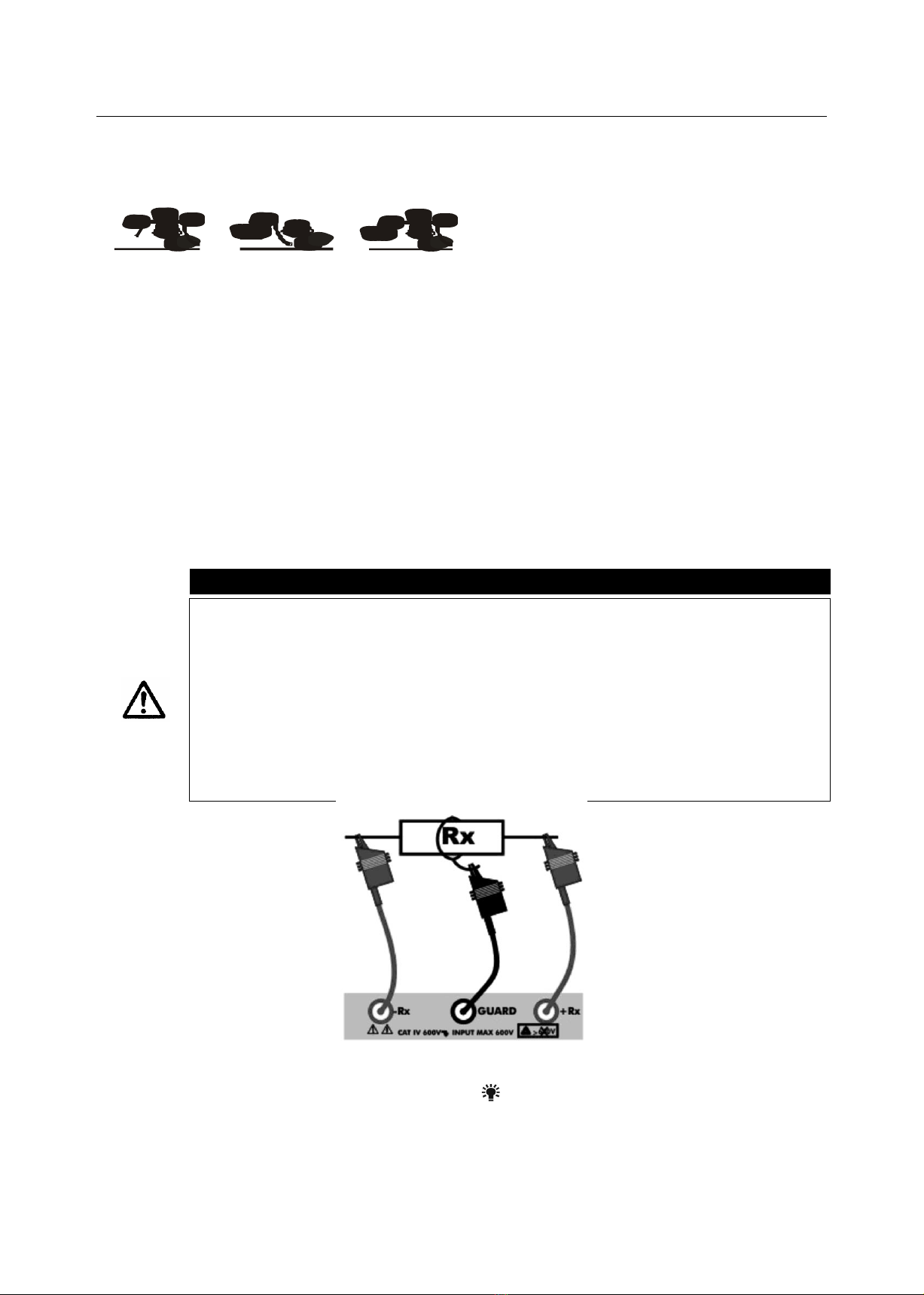
4.5 GUARD LEAD
In some cases, measurements could be affected by surface currents. By applying voltage to an
insulaon to be measured, there may be two disnct currents: one flowing in the test piece, the
other flowing on its surface. In case you want to measure only the resistance due to current Im
flowing in the test piece Rx (which is the significant one), it is necessary to absorb the surface
current If using another lead.
Fig. 3: Currents flowing in the test piece
4.6 NOTES ON THE INSULATION MEASUREMENTS
Measuring a high resistance such as the insulaon resistance is very difficult as the value of the
currents considered may be very low. When measuring, to prevent making mistakes, it is therefore
necessary to take the following precauons:
CAUTION
Keep the measuring leads suspended above the path or, anyway, make sure the
leads do not make contact in more of one point
While measuring high resistances, the area around the measuring instrument and
the appliance being tested must be free. It is recommended to use the mer
funcon so that the operator may keep at due distance from the leads and from
the resistance to be tested
It is recommended to use the GUARD lead to measure resistances of some tens of
GΩ or higher
While use the instrument with main supply, it's important to check that the
earthed resistance pole to measure is connected to the instrument Rx+
Terminal

8
4.7 SWITCH ON THE INSTRUMENT
Aer switch on, the instrument gives a short
acousc signal and, for approximately one
second, all segments of the display appear.
Then, the instrument shows the firmware
version, then it sets to the last measuring mode
selected before turning off.
4.7.1 Configuraon of the test parameters for FIX mode
If no test is being carried out, the instrument automacally turns off aer approximately 5
minutes aer the last me a key was pressed. To reacvate the instrument, it is necessary to turn
it on again by pressing the relevant key.

9
4.8 INSULATION MEASUREMENT IN FIX MODE
This measurement mode, performed in compliance with IEC/ EN61557-2 guideline, allows a quick
selecon of the test voltage among the values: 250, 500, 1000, 2500, and 5000VDC.
CAUTION
The instrument may be used on installaons of overvoltage category CAT IV 600V
to earth with maximum voltage 600V between inputs. Do not connect the
instrument to installaons with voltages exceeding the limit values indicated in
this manual. If these limit values are exceeded, the operator may be exposed to
electrical shocks and the instrument could get damaged
Always connect the measuring leads to the instrument and to the alligator clips
with the accessories disconnected from the system
It is recommended to hold the alligator clip respecng the safety area marked by
the hand protecon (see § 4.4)
Fig. 4: Instrument connecon
1. Turn on the instrument by press ON/OFF/ key
2. Press the FUNC/ERASE MEM key to select the “FIX” mode
3. The display shows a screen similar to that
reported here to the side, which contains:
The FIX selected mode
The bargraph set to zero
The "--- TΩ" indicaon
The selected test voltage
The test me value
The plug symbol (if the instrument is
supplied from the mains)
The baery symbol steadily
illuminated or flashing (if baeries are
flat or are being recharged)
The TIMER symbol if the duraon of
the test has been set

10
4. By pressing the arrow keys, the
instrument shows a screen similar to that
reported here to the side, which contains
the value of the input voltage.
5. Press the MODE/CLEAR SMOOTH key to set one of the following test voltages: 250V, 500V,
1000V, 2500V, 5000V
6. Insert the measuring leads into the relevant input leads of the instrument -Rx, +Rx and
GUARD, if necessary (see § 4.5 and Fig. 4)
CAUTION
Make sure that there is no voltage at the ends of the measuring points before
connecng them to the measuring leads.
7. Connect the alligator clips to the part of the system to be tested
8. Press the START/STOP key to perform measurement
CAUTION
The display shows the message "Measuring..." which indicates that the instrument is
performing the measurement. During this whole phase:
Do not disconnect the measuring leads of the instrument from the conductor
being tested; the conductor could remain live at a dangerous voltage because of
possible stray capacitances in the circuit tested;
Never insert the power cord into the Mains socket
9. During measurement, the instrument
gives a short acousc signal every second
and the display shows a screen similar to
that reported here to the side, which
contains:
The FIX selected mode
The bargraph proporonal to the
measured resistance value
The numerical indicaon of the
measured resistance
The applied test voltage
The symbol of the alarm bell (if the measured value is not within the set limits and/or if
the value of the test voltage is lower than the set nominal value)
The value of the test me elapsed or remaining (if a test has been set)
The plug symbol (if the instrument is supplied from the mains)
The baery symbol steadily illuminated or flashing (if baeries are flat or are being
recharged)
The mer symbol if the duraon of the test has been preset
The two "flash" symbols to indicate a dangerous voltage
The message "MEASURING..."

11
While measuring, it is also possible to display the leakage current, the DAR (Dielectric Absorpon
Rao if test duraon > 1 minute), the PI (Polarizaon Index if test duraon > 10 minutes) which
cyclically show when pressing the arrow keys (see § 11.1)
10. If no measuring me was set when seng the parameters or if you want to stop the test in
advance before the set me elapses, press the START/STOP key
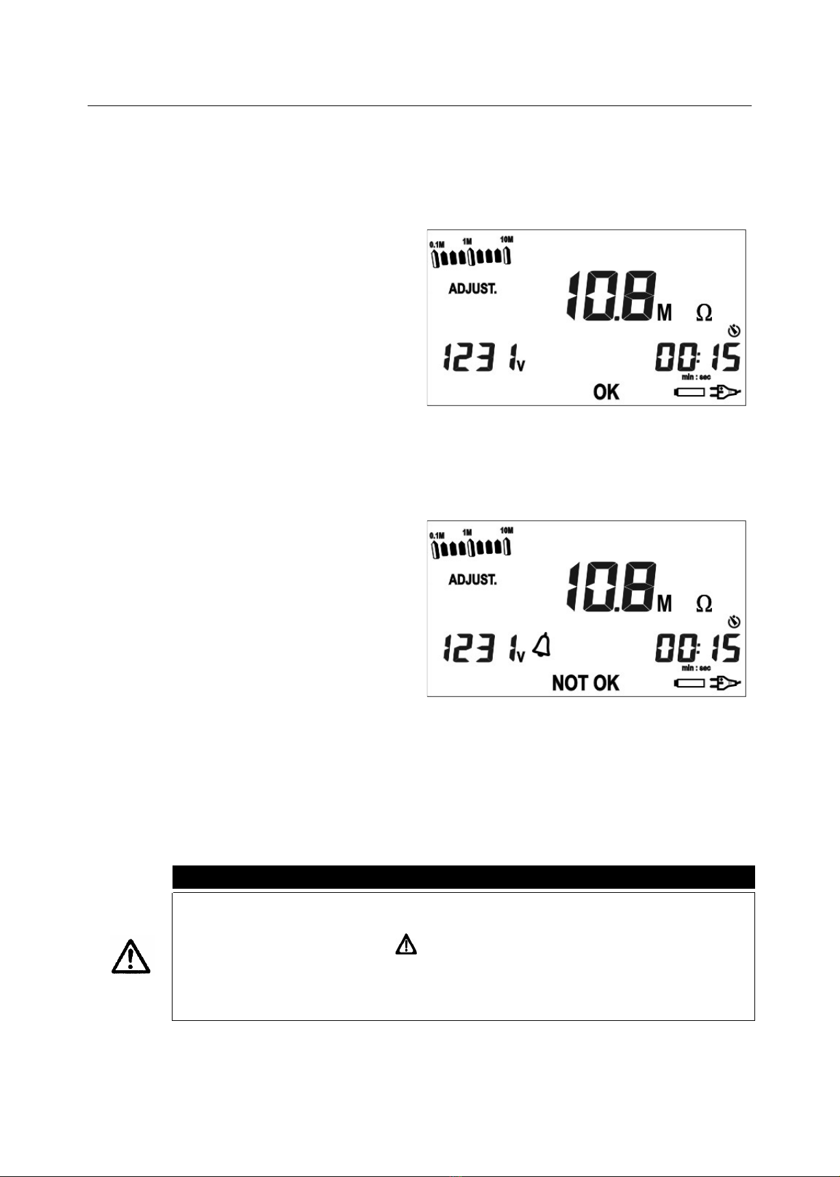
11a. Once measurement is complete and any
capacitance has been discharged, the
instrument shows:
The value of the measured insulaon
resistance;
The value of the generated voltage;
The duraon of the test
If the measured resistance value is
between the (MIN - MAX) limits
previously set, the instrument shows
OK and gives a double acousc signal
(see § 4.10.1)
OR
11b. Once measurement is complete and any
capacitance has been discharged, the
instrument shows:
The value of the measured insulaon
resistance
The value of the generated voltage
The duraon of the test
If the measured resistance value is not
between the (MIN - MAX) limits
previously set, the instrument shows
NOT OK, the alarm bell and gives a
long acousc signal (see § 4.10.1)
12. Once measurement is complete, it is also possible to display the leakage current, the DAR
(Dielectric Absorpon Rao), the PI (Polarizaon Index) and the cap acitance which cyclically
show when pressing the arrow keys (see § 11.1)
CAUTION
If the measured resistance value < 5.0MΩ , the screen displaying the capacitance
shows three hyphens “---“, to indicate that it was impossible to measure the
capacitance, and the symbol
If, when scrolling the results obtained, the capacitance value is > 1nF, it is
recommended to repeat the measurement by acvang the SMOOTH funcon
(see § 4.11)
13. Measures can be saved by pressing the SAVE key twice (see § 5.1)

12
4.8.1 Configuraon of the test parameters for FIX mode
a. By cyclically pressing the SET/DISPLAY MEM key, it is possible to select the following
parameters:
Minimum value of the insulaon (MIN) in a range between 0,01MΩ - MAX
Maximum value of the insulaon (MAX) in a range between (MIN) - 10TΩ
Test me value in a range between (00min:05sec) - (99min:59 sec)
b. Press the arrow keys to change the value of the parameters (a long pressing of the keys
allows a rapid change of the values)
c. Press the MODE/CLEAR SMOOTH key to remove the limit values set for the parameters. The
display shows the message "no" to indicate that there is no limit set.
d. Aer seng, press the SAVE key to save the changes made or press the ESC/RECALL MEM
key to exit without saving and return to the previous screen

13
4.9 INSULATION MEASUREMENT IN ADJUST MODE
This funcon is performed in compliance with IEC/ EN61557-2 guideline. The ADJUST mode allows
the fine adjustment of the test voltage between 100 - 5000VDC.
CAUTION
The instrument may be used on installaons of overvoltage category CAT IV 600V
to earth with maximum voltage 600V between inputs. Do not connect the
instrument to installaons with voltages exceeding the limit values indicated in
this manual. If these limit values are exceeded, the operator may be exposed to
electrical shocks and the instrument could get damaged
Always connect the measuring leads to the instrument and to the alligator clips
with the accessories disconnected from the system
We recommend holding the alligator clip respecng the safety area marked by
the hand protecon (see § 4.4)
Fig. 5: Instrument connecon
1. Turn on the instrument by pressing the relevant key
2. Press the FUNC/ERASE MEM key to select the “ADJUST” mode
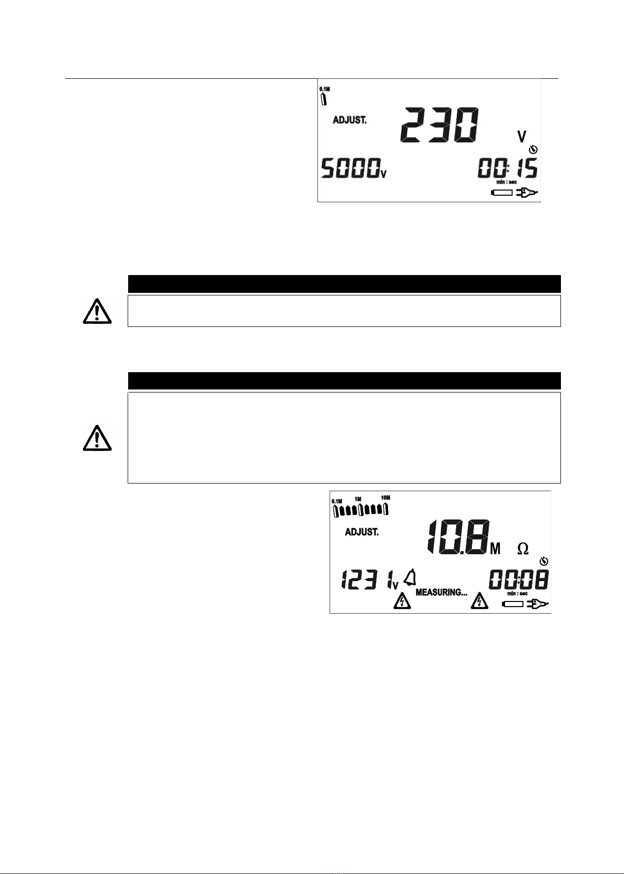
3. The display shows a screen similar to that
reported here to the side, which contains:
The ADJUST funcon selected
The bar graph set to zero
The indicaon "--- TΩ"
The test voltage
The value of the test me
The plug symbol (if the instrument is
supplied from the mains)
The baery symbol steadily
illuminated or flashing (if baeries are
flat or are being recharged)
The mer symbol if the duraon of the
test has been preset
14
4. By pressing the arrow keys, the
instrument shows a screen similar to that
reported here to the side, which contains
the value of the input voltage.
5. Make sure that the set test voltage is the desired one. Should it not be the case, please refer
to § 4.9.1 to change it
6. Insert the measuring leads into the relevant input leads of the instrument -Rx, +Rx and
GUARD, if necessary (see § 4.5 and Fig.5)
CAUTION
Make sure that there is no voltage at the ends of the measuring points before
connecng them to the measuring leads.
7. Connect the alligator clips to the part of the system to be tested.
8. Press the START/STOP key to perform measurement
CAUTION
The display shows the message “Measuring…” which indicates that the instrument is
performing the measurement. During this whole phase:
Do not disconnect the measuring leads of the instrument from the conductor
being tested; the conductor could remain live at a dangerous voltage because of
possible stray capacitances in the circuit tested
Never insert the power cord into the Mains socket
9.
During measurement, the instrument gives a
short acousc signal every second and the
display shows a screen similar to that
reported here to the side, which contains:
The ADJUST funcon selected
The bar graph proporonal to the
measured resistance value
The numerical indicaon of the
measured resistance
The actual test voltage
The symbol of the alarm bell (if the measured value is not within the set limits and/or if
the value of the test voltage is lower than the set nominal value)
The value of the test me elapsed or remaining (if a test has been set)
The plug symbol (if the instrument is supplied from the mains)
The baery symbol steadily illuminated or flashing (if baeries are flat or are being
recharged)
The mer symbol if the duraon of the test has been preset
The two “flash” symbols to indicate a dangerous voltage
The message “MEASURING…”
15
While measuring, it is also possible to display the leakage current, the DAR (Dielectric
Absorpon Rao if test duraon > 1 minute), the PI (Polarizaon Index if test duraon > 10
minutes) which cyclically show when pressing the arrow keys (see §11.1)
10. If no measuring me was set when seng the parameters or if you want to stop the test in
advance before the set me elapses, press the START/STOP key
11a. Once measurement is complete and any
capacitance has been discharged, the
instrument shows:
The value of the measured insulaon
resistance
The value of the generated voltage
The duraon of the test
If the measured resistance value is
between the (MIN - MAX) limits
previously set, the instrument shows
OK and gives a double acousc signal
(see § 4.9.1)
OR
11b. Once measurement is complete and any
capacitance has been discharged, the
instrument shows:
The value of the measured insulaon
resistance
The value of the generated voltage
The duraon of the test
If the measured resistance value is not
between the (MIN - MAX) limits
previously set, the instrument shows
NOT OK, the alarm bell and gives a
long acousc signal (see § 4.9.1)
12. Once measurement is complete, it is also possible to display the leakage current, the DAR
(Dielectric Absorpon Rao), the PI (Polarizaon Index) and the capacitance which cyclically
show when pressing the arrow keys (see § 11.1)
CAUTION
If the measured resistance value < 5,0MΩ , the screen displaying the capacitance
shows three hyphens “---“, to indicate that it was impossible to measure the
capacitance, and the symbol
If, when scrolling the results obtained, the capacitance value is > 1nF, it is
recommended to repeat the measurement by acvang the SMOOTH funcon
(see § 4.11)
13. Measures can be saved by pressing the SAVE key twice (see § 5.1)

16
4.9.1 Configuraon of the test parameters for ADJUST mode
a. By cyclically pressing the SET/DISPLAY MEM key, it is possible to select the following
parameters:
Minimum value of the insulaon (MIN) in a range between 0.01MΩ - MAX
Maximum value of the insulaon (MAX) in a range between (MIN) - 10TΩ
Value of the test voltage in a range between 100V - 5000V (can be set in steps of 25V up
to 1000V and in steps of 50V from 1000V to 5000V)
Test me value in a range between (00min:05sec) - (99min:59 sec).
b. Press the arrow keys to change the value of the parameters (a long pressing of the keys
allows a rapid change of the values).
c. Press the MODE/CLEAR SMOOTH key to remove the limit values set for the parameters. The
display shows the message "no" to indicate that there is no limit set. Only when seng the
value of the test voltage, by pressing the MODE/CLEAR SMOOTH key, the voltage sets to
the default value of 1000V.
d. Aer seng, press the SAVE key to save the changes made or press the ESC/RECALL MEM
key to exit without saving and return to the previous screen
17
4.10 INSULATION MEASUREMENT IN RAMP MODE
This funcon is performed in compliance with standard IEC/ EN61557-2. The RAMP mode allows
choosing among three different types of ramps:
RAMP#1 RAMP#2 RAMP#3
For each type of ramp, it is possible to set the duraon, the test voltage and the number of mes
the ramp is repeated (§ 4.10.1, § 4.10.2, § 4.10.3).
RAMP#1: Voltage starts from 0V, reaches the value V1 in a me interval T, keeps the value
V1 for a me T1, and finally returns to 0 (with possible discharge of the residual
voltage).
RAMP#2: Voltage starts from 0V, which is kept for a me T0, reaches the value V1 in a me
interval T, and finally returns to 0 (with possible discharge of the residual voltage).
RAMP#3: Voltage starts from 0V, which is kept for a me T0, reaches the value V1 in a me
interval T, keeps to value V1 for a me T1, and finally returns to 0 (with possible
discharge of the residual voltage).
CAUTION
The instrument may be used on installaons of overvoltage category CAT IV 600V
to earth with maximum voltage 600V between inputs. Do not connect the
instrument to installaons with voltages exceeding the limit values indicated in
this manual. If these limit values are exceeded, the operator may be exposed to
electrical shocks and the instrument could get damaged
Always connect the measuring leads to the instrument and to the alligator clips
with the accessories disconnected from the system
It is recommended to hold the alligator clip respecng the safety area marked by
the hand protecon (see § 4.4)
Fig. 6: Instrument connecon
1. Turn on the instrument by press the ON/OFF/ key
2. Press the FUNC key to select the RAMP funcon
18
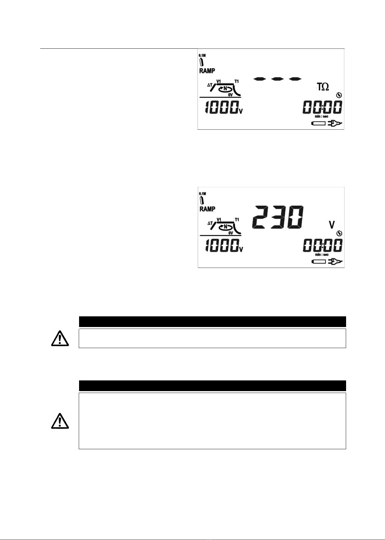
3. The display shows a screen similar to that
reported here to the side, which contains:
The RAMP type selected
The bar graph set to zero
The indicaon "--- T "
The set test voltage
The value of the test me
The plug symbol (if the instrument is
supplied from the mains)
The baery symbol steadily illuminated
or flashing (if baeries are flat or are
being recharged)
The mer symbol if the duraon of the
test has been preset.
4. By pressing the arrow keys, the instrument
shows a screen similar to that reported
here to the side, which contains the value
of the input voltage.
5. Insert the measuring leads into the relevant input leads of the instrument -Rx, +Rx and
GUARD, if necessary (see § 4.5 and Fig. 6)
CAUTION
Make sure that there is no voltage at the ends of the measuring points before
connecng them to the measuring leads.
6. Connect the alligator clips to the part of the system to be tested.
7. Press the START/STOP key to perform measurement.
CAUTION
The display shows the message "Measuring..." which indicates that the instrument is
performing the measurement. During this whole phase:
Do not disconnect the measuring leads of the instrument from the conductor
being tested; the conductor could remain live at a dangerous voltage because of
possible stray capacitances in the circuit tested
Never insert the power cord into the Mains socket

19
8. During measurement, the instrument gives
a short acousc signal every second and
the display shows a screen similar to that
reported here to the side, which contains:
The RAMP funcon selected
The bar graph proporonal to the
measured resistance value
The numerical indicaon of the
measured resistance
The segment relevant to the current ramp point, flashing
The actual test voltage (relevant to the current ramp point)
The symbol of the alarm bell (if the measured value is not within the set limits and/or if
the value of the test voltage is lower than the set nominal value)
The value of the remaining test me (relevant to the current ramp point)
The plug symbol (if the instrument is supplied from the mains)
The baery symbol steadily illuminated or flashing (if baeries are flat or are being
recharged)
The mer symbol
The two "flash" symbols to indicate a dangerous voltage
The message "MEASURING..."
While measuring, it is also possible to display the leakage current, the capacitance the
number N of the cycle the instrument is performing, which cyclically show when pressing
the arrow keys.
9. .. If you want to stop the test in advance before the set number N of cycles is reached, press
the START/STOP key.
10a. Once measurement is complete and any
capacitance has been discharged, the
instrument shows:
The value of the measured insulaon
resistance
The value of the actually generated
voltage V1
The value of the me relevant to
parameter T1
If the measured resistance value is
between the (MIN - MAX) limits
previously set, the instrument shows
OK and gives a double acoustic signal
(see § 4.10.1, § 4.10.2, § 4.10.3)
OR
Table of contents
Other Sifam Tinsley Test Equipment manuals


