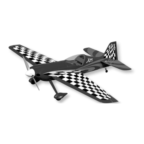
SIG SUKHOI SU-31 ARF User manual

1
required to fly your SUKHOI SU-31 - rudder, elevator, ailerons, and
throttle. However, you will require a total of six servos - ailerons
(2), elevators (2), rudder (1), and throttle (1).
SERVOS: Since your SUKHOI SU31 is a large, highly aerobatic
airplane and because the control surfaces are also large, we urge
you to use appropriate servos on all the flight surfaces (ailerons,
elevator and rudder). This model should not be flown with
"standard" 40 - 50 inch/ounce output servos! The SUKHOI is big
enough to impart very large air loads and standard servos will
quickly fail, resulting in loss of control. You should use heavy-duty
ball-bearing servos with at least 70 inch/ounces of torque or more
to drive the ailerons, elevators and rudder. If available, use a servo
with metal gears instead of plastic gears. Specifically in our
prototype models, we used Airtronics™ #94731 servos for the
ailerons, elevators, and rudder. This is a dual ball-bearing servo,
rated at 77 inch/ounces of torque. Another good choice is the
Hitec™ #605MG servo, which has 76 inch/ounces of torque
and metal gears. These servos or their equivalent from other
manufacturers, can be relied upon to work well throughout the
SUKHOI's flight envelope. A "standard" servo is adequate for the
throttle.
SERVO ARMS: We also suggest that you consider using after-
market reinforced plastic servo output arms, such as the Du-Bro
"Super Strength" products. These output arms are available to fit
any brand of servo. They are very strong and work well with this
model. We highly recommend their use with the pull-pull rudder
system used in this SUKHOI. Using typical plastic servo output
arms with the braided steel cables for rudder control, may cause
problems due to the potential of wearing of the plastic by the
cables over extended use. The Du-Bro output arms are molded
from considerably tougher material and these have held up
extremely well in our prototypes.
SERVO EXTENSION CHORDS: You will need two 12" extension
chords and one standard Y-harness chord for the aileron servos;
one 24" extension chord for the rudder servo; and one Y-harness
chord for the elevator servos. Y-harness chords are used to
connect two servos to a single plug-in in the receiver. In the case
of the two aileron servos, a standard Y-harness chord, available
from your radio manufacturer, will work fine. In the case of the two
elevator servos, see the following note about a special kind of
Y-harness called the "MiracleY".
MIRACLE "Y": Note in the photos that the elevator servos will be
mounted on opposite sides of the fuselage in exact "mirror image"
to each other (i.e.; with the pushrods coming off the top of each
servo in direct line with the control horns). This is done so
the geometry of the servos, pushrods, and horns is exactly
symmetrical on both sides, providing the exact same response to
control inputs for each elevator. This is very important in an all out
aerobatic machine like the SUKHOI. Normally in order to have this
R
SUKHOI SU-31 ARF ASSEMBLY MANUAL
INTRODUCTION:
Congratulations on your purchase of the SIG SUKHOI SU-31 ARF
kit! We're confident that this SUKHOI will quickly become one of
your favorite models, provided it is properly assembled and
adequately powered.
This SUHKOI kit features some of the lightest, best engineered
construction of any ARF on the market. It is remarkably light and
strong! This is one of the reasons it flies as well as it does, using
the recommended engine sizes. The SUKHOI has superb take-off
and landing characteristics combined with unlimited aerobatic
capabilities. The airframe has been specifically designed to
provide you with a "zeroed out" model. This is to say that the
wings and horizontal stabilizer sit at 0Oin relationship to the thrust
line. In turn, this provides you with a model that is completely
"honest" in any attitude. We will cover more detailed set-up
information later in the assembly instructions.
3D CAPABLE! For those of you who are interested in 3-D
aerobatics, we have provided the SUKHOI with double beveled
aileron, elevator and rudder hinge lines. This means that the
control surfaces can be driven to throws in excess of 45Ofor
extreme 3-D maneuvers!
ENGINE NOTE: Due to the large number of useable engines
for this model, we simply cannot cover every possible engine
installation. However, the volume of space provided inside the
large cowling should make it easy to mount virtually any engine
within the suggested size range.
EASY TO ASSEMBLE! We urge you to follow these assembly
instructions closely to produce the model as it is intended to be.
We understand that many modelers love to "kit bash" and
incorporate their own modifications. Simply be aware that certain
assembly procedures for this airplane must be followed in the
correct sequence. Deviation from these instructions could lead to
problems beyond our control. Plan carefully!
ADDITIONAL ITEMS NEEDED TO COMPLETETHIS MODEL
RADIO EQUIPMENT
We highly recommend the use of a modern programmable
computer radio. Such radio systems allow you to easily set and
adjust every channel and additionally pre-program various flight
functions to suit your individual style of flying. Four channels are

2
type of setup work properly with a standard Y-harness you would
have to electronically reverse the wiring inside one of the elevator
servos so that both elevators will go up (or down) at the same time.
However, there is an after-market Y-harness available that
electronically reverses one of the elevator servos for you. It also
has a centering adjustment pot that lets you dial in the elevators
exactly to a neutral relationship with each other. The product is
called the "MIRACLE Y™ Servo Reversing Y Adapter", sold
by MAXX PRODUCTS of Lake Zurich, IL. It can be ordered with
any radio manufacturer's connectors you specify. We have
thoroughly tested this product and found it to be reliable, easy to
use and very reasonably priced. In addition, it is a total of 24" in
length - 12" of elevator extension cables and a 12" cable lead to
the receiver. Perfect for the SUKHOI SU-31.
RX BATTERY PACK: Finally, since you will be using a total of six
servos to fly this airplane, we strongly suggest you use a large
capacity battery pack for use in this model. We have used both
1000 mAH and 1200 mAH packs with very good results. Using the
light 1000 mAH pack, we have been able to safely fly five or six
flights during any given flying session, a reasonable amount of
flying time for most modelers. Naturally, a larger pack provides
more flight time but remember that larger can also equate to
heavier. We also suggest that you routinely use an Expanded
Scale Voltmeter (ESV) at the field to check the charge condition of
your batteries. This common piece of field equipment can save
your model!
ENGINE & SPINNER
The SIG SUKHOI SU-31 has been flown with a wide variety of
engines. As everyone knows, there is no substitute for power, and
the engines recommended for this model all provide good power
margins. Naturally, the larger engines in this range make more
power and will fly the SUKHOI with more authority than the small-
er engines. It is simply a matter of how you want to fly the airplane.
RECOMMENDED ENGINES
2-STROKE GLOW ENGINES: 1.50 - 2.10 cu.in.
4-STROKE GLOW ENGINES: 1.80 - 2.70 cu.in.
GAS ENGINES: 2.4 cu.in.
GLOW ENGINES:
GAS ENGINES: Our preferred engine for the SUKHOI is a 2.4 cu.
in. gas engine. Our hands down favorite is the FIRST PLACE
ENGINES FPE 2.4 cu. in. gas engine, available from SIG.
Weighing only 52 ounces, this compact powerhouse delivers
approximately 18 pounds of thrust with a 20x10 prop. You can
imagine how that makes a 14 pound SUKHOI perform!
If you use a gas engine in your SUKHOI, be aware that the fuel
tank stopper and the fuel tubing that are supplied in this kit ARE
NOT gasoline compatible. Be sure to replace them with suitable
after market components. The kit supplied fuel tank body itself is
gasoline compatible.
SPINNER: Regardless of which engine you use in your SUKHOI,
we recommend that you obtain a high quality 3-1/4" dia. aluminum
spinner. Do not use a plastic spinner for engines this large.
KIT CONTENTS
The following is a complete list of every part included with your
SUKHOI SU-31 ARF kit. Use the check-off blocks to inventory
your kit before beginning assembly.
BAG 1: RIGHT WING
❑1 Right Wing Panel
❑1 Right Aileron
❑4 Hinge Points, installed but not glued
BAG 2: LEFT WING
❑1 Left Wing Panel
❑1 Left Aileron
❑4 Hinge Points, installed but not glued
BAG 3: FIN & RUDDER:
❑1 Fin
❑1 Rudder
❑3 Hinge Points, installed but not glued
BAG 4: STABILIZER & ELEVATORS
❑1 Stabilizer
❑1 Right Elevator
❑1 Left Elevator
❑6 Hinge Points, installed but not glued
BAG 5: FUSELAGE
❑1 Fuselage
❑1 Landing Gear Fairing
❑2 M2.6 x 12mm PWA* Screws, for l.g. fairing
❑1 Molded Plastic Canopy Base
❑1 Molded Clear Plastic Canopy
❑6 M2.6 x 10mm PWA* Screws, for canopy
BAG 6: COWLING
❑1 Fiberglass Cowling
❑4 M2.6 x 10mm PWA* Screws
BAG 7: WING FAIRING
❑1 Molded Plastic Wing Fairing
BAG 8: TAIL FAIRING
❑1 Molded Plastic Tail Fairing
BAG 9: MAIN LANDING GEAR
❑1 Aluminum Landing Gear
❑4 M4 x 15mm PWA* Bolts
GAS ENGINE
4-STROKE
ENGINE 2-STROKE
ENGINE
Saito 1.80
Irvine 1.50
FIRST PLACE ENGINES
FPE 2.4

3
❑4 M4 Lock Nuts
❑2 Hardened Steel Axles
❑2 Lock Nuts, for axles
❑4 Wheel Collars with Set Screws
❑2 3-1/2" dia. Main Wheels
BAG 10: TAILWHEEL ASSEMBLY
❑1 Main Leaf-Spring with Steering Arm, WheelYoke, and
Tailwheel installed
❑1 Short Leaf-Spring
❑2 Coil Steering Springs
❑1 Metal Rudder T-Horn
❑2 M2 x 9mm PWA* Screws
❑3 M3 x 14mm PWA* Screws
BAG 11: FUEL TANK
❑1 450cc (15.2 oz.) Plastic Tank
❑1 Rubber Stopper
❑1 Metal Front Clamp
❑1 Metal Rear Clamp
❑1 M3 x 18mm Clamp Bolt
❑1 Metal Clunk Pickup
❑1 Fuel Tubing for inside tank
❑3 Aluminum Tubes
❑2 Fuel Tubing
BAG 12: SMALL PARTS
❑16 M2.6 x 10mm PWA* Screws, for fuselage hatch(4),
aileron servo hatches(8), aileron servo mount blocks(4)
❑1 Plywood Right Aileron Servo Hatch
❑1 Plywood Left Aileron Servo Hatch
❑1 Hardwood Front Wing Joiner
❑1 Aluminum Tube Rear Wing Joiner
❑1 Plywood Front Wing Former WF-1
❑1 Plywood Rear Wing Former WF-2
❑1 1/8" x 3-1/2" x 7-1/2" Plywood Front Fuselage Hatch
❑4 3/8" x 3/4" x 3/4" Hardwood Aileron Servo Mounts
❑2 1/8" x 3/4" x 3/4" Plywood Wing Bolt Plates
❑1 1/8" Plywood Throttle Servo Tray
❑1 1/8" Plywood Throttle Pushrod Support
❑2 3/8" dia. x 1-5/8" long Hardwood Dowels
MISCELLANEOUS PARTS
❑2 1/4-20 x 2" Nylon Wing Bolts
❑2 RIGHT Metal Control Horns; for ail.(1), ele.(1)
❑3 LEFT Metal Control Horns; for ail.(1), ele.(1), rud.(1)
❑24 M2.6 x 10mm Metal Screws; for control horns
❑2 4-40 X 2-3/4" Threaded Pushrods; for elevator
❑2 4-40 X 4" Threaded Pushrods; for ailerons
❑1 4-40 X 4-5/8" Threaded Pushrod; for rudder
❑5 4-40 Threaded R/C Links; ail.(2), ele.(2), rud.(1)
❑5 4-40 Hex Nuts; jam nuts R/C Links
❑5 4-40 size Solder Links; ail.(2), ele.(2), rud.(1)
❑1 1/16"od x 18" Stranded Steel Cable; for thr. pushrod
❑1 1/8"od x 18" Nylon Pushrod Tubing, for thr. pushrod
❑1 2-56 size Solder Link; for engine end of thr. pushrod
❑1 Brass Pushrod Connector; for servo end of thr. pushrod
❑1 Molded Nylon Retainer; for pushrod connector
❑1 4-40 x 1/8" Socket-Hd Cap Screw; for pushrod connector
❑1 2-56 x 10" Threaded Rod; for thr. pushrod (for gas)
❑1 Instrument Panel Print
❑1 Decal Sheet
* PWA = phillips washer-style head
NOTES ABOUTTHE COVERING MATERIAL
Your SUKHOI SU-31 ARF has been professionally covered with
Oracover®#12 Cream, #40 Green, and #71 Black.(Note: In the
United States, Oracover®is sold under the name of Hangar 9
Ultracoat®. The equivalent Ultracoat®colors are called #878
Cream, #880 Green, #874 Black).
Oracover®is well known for its ease of application, light weight,
and consistency of color. If you live in a drier climate, you may
notice that some wrinkles might develop after removing the
covered parts from their plastic bags. If that is the case, there is
no need to be alarmed. The covering is not defective. This is
perfectly normal and has nothing to do with the covering material
or how it was applied. It has to do with the wood beneath the
covering. Wood takes on or loses ambient humidity. Your SUKHOI
ARF was manufactured in a relatively humid region of the world.
The wood was therefore holding humidity at the time the parts
were covered and bagged. Once the parts are removed from their
bags and subjected to drier conditions, the wood quickly loses
moisture and the covering may appear loose. (This also explains
why most iron-on coverings stay tight in the summer only to loosen
a little in drier winter conditions.)
Any wrinkles that appear in the covering are easy to remove
by using a hobby-type heat iron. We suggest covering the iron's
shoe with a thin cotton cloth, such as an old T-shirt, to prevent
scratching the film. The iron should be set to about 280O- 300OF.
First, use the heated iron to go over all the seams and color joints
in the covering, making they are all sealed and well adhered. Then
use the heated iron to lightly shrink the material - do not press on
it. Once the covering is tight, lightly iron the material back down to
the wood. You can also use a hobby-type heat gun to re-shrink
the covering, but you must be extra careful around the seams.
Re-heating seams may cause them to "creep", making them
unsightly.
REQUIRED TOOLS
For proper assembly, we suggest you have the following tools and
materials available:
A selection of glues - SIG Thin, Medium and Thick CA,
and SIG Kwik-Set 5-Minute Epoxy
Threadlock Compound, such as Loctite®Non-Permanent Blue
Silicone Sealer - clear or white
Screwdriver Assortment
Pliers - Needle Nose & Flat Nose
Diagonal Wire Cutters
Small Allen Wrench Assortment
Drill with Assorted Drill Bits
Pin Vise for Small Dia. Drill Bits
Hobby Knife With Sharp #11 Blades
Scissors
Covering Iron and Trim Seal Tool
MODELER’S TIP: One of the most common problems
associated with shrinking any covering film is controlling the
heat around seams. Heat applied close to or directly onto
seams re-heats the covering adhesive and the seam will often
"crawl". This is easy to control. Just tear a few paper towels
into strips and soak them in cool tap water. Lay the wet strips
over any covering seam and use your heat gun or iron as you
normally would. The wet strips keep the seam cool while the
covering immediately next to it shrinks. This tip works great
with any iron-on covering.

4
tabs that are in the wing. Remove the hatch. Redrill the holes in
the hatch with a 7/64" dia. bit to allow clearance for the screws.
❑3) The aileron servos are mounted to the back, uncovered
sides of the servo hatches. From the kit contents, locate the four
3/8" x 3/4" x 3/4" hardwood aileron servo mounts. You will also
need the servos and the servo mounting grommets and screws
supplied by your radio manufacturer during this step. Remove the
servo output arm and lay the servo flat on its side. Position two of
the mounting blocks beneath the servo's mounting arms, also
flat on the same surface as the servo. Drill appropriate servo
mounting holes into the wood mounting blocks. Use the screws
that came with your radio system to now mount the servos to the
two mounting blocks.
Masking Tape
Paper Towels
Power Drill With Selection of Bits
Dremel®Tool with Selection of Sanding and Grinding Bits
Soldering Iron and Solder
Large Fuel Tubing
WING ASSEMBLY
Before starting actual construction, trial fit both wing panels onto
the Hardwood Wing Joiner and the Aluminum Tube Rear Wing
Joiner. Check to see that the wing panels fit together in proper
alignment, and that both root ribs come into firm, straight contact
with each other. If the Hardwood Wing Joiner requires a little
trimming to achieve this fit, do so now. NOTE: Be sure you've got
the Hardwood Wing Joiner right side up - the greater angles are
on the bottom. Do not glue the wing panels together yet!
❑1)
Locate the two pre-covered aileron servo hatches and eight
M2.6 x 10mm PWA Screws. Trial fit the hatches into the aileron
servo openings to determine which hatch goes in the right wing and
which goes in the left wing. Tape the hatches in place, aligning their
servo arm cutouts with the ones in the wing openings.
❑2) Drill a 3/64" (or #56) dia.hole near each corner of the hatch.
Drill completely thru the hatch and into the hardwood mounting

5
❑4) Install the output arm back onto the aileron servo, in neutral
position. Place the servo/mounting block assembly onto the
backside of the servo hatch, centering the output arm with the half
slot opening. The servo output arm must be able to move freely
back and forth without touching the slot's edge - about 1/32"
clearance is adequate. With the servo now in this position, use a
sharp pencil to mark the locations of the servo mounting blocks
onto the hatch. Remove the servo from the hatch and apply thick
CA glue or 5-minute epoxy to the bottoms of the servo blocks and
glue them in place to the hatch, again checking for output arm
clearance. Hold or clamp the block in exact position until dry.
Repeat this step to mount the other aileron servo to its hatch.
❑5) Locate four M2.6 x 10mm PWA Screws. These screws will
be used to mechanically secure each servo mounting block to the
servo hatches. Use a ruler to find the approximate center of each
block and mark the location onto the covered side of the servo
hatch. With a 3/64" (or #56) dia. bit, drill a pilot hole - about 1/4"
deep - through the servo hatch and into the mounting block, at the
marks just made. Install and tighten the screws in place.
❑6) Before installing the aileron servos/hatches into the wing
panels, use your radio system to center both servos and to check
servo travel. Make sure both servo output arms are 90Oto the
servos and that they are long enough to clear the wing's bottom
surface during extremes of travel.
a. Now attach 12" long servo extension chords to both
aileron servos.
(Note: Be sure to put a piece of tape around the
connecting plugs so they can’t come apart while hidden in the wing.)
b. Feed the servo extension chords into the wings through the
servo hatch opening, then through the holes in the ribs and finally
out through the round holes provided at the center of each wing
panel. (Note that a piece of string has been factory-installed in the
wing panels to make it easy to pull the extension chords through
the wing.)
c. After you get the end of the extension chord all the way
through the wing, tape the loose end of the chord to the wing's top
surface, so that it won't fall back inside the wing.
d. Finally, secure the aileron servo/hatch in place in the wing
with M2.6 x 10mm PWA Screws. (NOTE: Did you remember to
install the servo output arm screws in each servo?)
❑ 7) Next you need to permanently glue the aileron hinges in
place. Notice that 4 hinges have been factory-installed in the each
aileron, but they are not glued.
a. First remove the all the hinges from the ailerons and wing.
b. Notice that the holes the hinges came out of are the correct
diameter for the round shank of the hinge, but not large enough to
accept the square "knuckle" part of the hinge. You need to
countersink the holes to accept the knuckle part of the hinge, so

6
Next apply glue to the hardwood front wing joiner and to the
aluminum tube rear wing joiner. Next slide the wing joiners into
one wing panel, and then slide the other wing panel in place over
the exposed end of the joiners, joining the two panels at the
center. Firmly press the wing panels together and wipe off any
excess glue with a paper towel and alcohol. Make sure the wing
panels are accurately aligned with each other by checking the
alignment of the leading and trailing edges. Use tape at the
leading and trailing edge joints to hold them in the correct position.
Place a clean rag on the floor next to a wall. Stand the wing
upright, with one wing tip on the cloth, as vertical as possible,
leaning against the wall. Place a weight on the upper wing tip and
allow this assembly to fully cure. Continue watching for excess
epoxy oozing out of the joint as it cures and wipe it off.
NOTE: It's very important to use plenty of epoxy when gluing the
wing panels together. The strength of your wing joint depends on
it! Don't worry if the excess glue oozes out and gets on the
covering material. With slow-drying epoxy, you will have plenty of
time to clean up all the glue smears with a paper towel soaked in
rubbing alcohol. Also, if possible get someone to help you with this
procedure. An extra set of hands makes the job much easier!
While one person holds the two wing panels firmly together in
correct alignment, the other person can clean off the excess glue
and tape the wing panels together.
❑9) Locate the 1/8" thick plywood part WF-1 and trial fit it in
place on the front of the wing. The top edge of WF-1 must fit flush
with the top surface of the wing. Also make sure WF-1 seats
tightly against the front surface of the wing. There should be no
gaps! If there is a gap, find out what's causing it and fix it. Once
you are satisfied that the plywood former fits properly, glue it
securely in place. Let dry.
❑10) Using a 3/8" dia. bit, drill two holes in the front of the wing
for the 3/8" dia. x 1-5/8" long leading edge dowels. The holes in
WF-1 show the exact locations. Drill completely through the
foremost wing structure, including the hardwood wing joiner.
that the hinge can be pushed in far enough for the pivot point to
line up with the front "V" point of the aileron leading edge. We
recommend enlarging the opening of the hinge holes slightly with
a hand-held 1/4" dia. drill bit. You only need to twist the drill bit
in about an 1/4" or so. Countersink all of the hinge holes in the
leading edge of the ailerons in this manner. This will allow a
gapless hinge line with proper hinge movement.
c. Trial fit the ailerons back onto all the hinges and the wing one
more time to make sure everything lines up properly. You want the
beveled leading edge of the aileron to be as close to the mating
wing as possible while still allowing full movement. When satisfied
that everything is good, take it back apart for the gluing process.
d. We recommend using slow drying epoxy glue for gluing the
hinges so that you will have ample time for cleanup and alignment.
Epoxy the hinges into the ailerons first and let dry. Then hinge
each aileron to its appropriate wing panel. The best procedure
with this type of hinge is to inject the glue into the hole and then
insert the hinge. Use a clean cloth soaked with methanol or
rubbing alcohol to wipe off any excess glue that has oozes out
onto the control surface. Then move on to the next hinge.
IMPORTANT NOTE: Be sure to correctly identify which aileron is
for the right wing and which is for the left wing by looking for the
aileron horn plywood mounting pad that is inset into the BOTTOM
side of each aileron, underneath the covering.
❑8) Now it's time to glue the wing panels together permanently!
Start by mixing up an ample amount of slow-drying epoxy glue.
Use a wire, stick or small throw-away brush to liberally coat the
inside of the wing joiner pockets in the end of the wing panels with
glue. Then apply a liberal coat of epoxy to the exposed center ribs
of each wing panel.
MODELER’S TIP: Apply a coat of petroleum jelly, such as
Vaseline®, to the hinge knuckle. The petroleum jelly will keep
the epoxy from sticking to the knuckle and causing a bind. Do
not get petroleum jelly on the round shank of the hinge, where
you want the glue to stick.

7
❑ 14) Locate the two nylon wing bolts. Mount the wing in place
on the fuselage, using the nylon wing bolts. The nylon wing bolts
should pass freely through the holes in the wing and thread into
the blind nuts that are pre-installed in the fuselage. If the wing
does not assemble cleanly and freely to the fuselage at this point,
you need to find the cause of any binding and fix it now, before
proceeding.
❑ 15) With the wing mounted to the fuselage, check the fit of the
1/8" thick plywood part WF-2. This part is to be glued to the
trailing edge of the wing. Before gluing, carefully remove the
covering material in the area where WF-2 contacts the wing, so
that you will have a good wood-to-wood joint. Then glue WF-2
securely in place on the wing.
NOTE: In order to allow the wing to slide on and off easily, it's best
to have a slight gap (1/16" maximum) between WF-2 and the
adjacent fuselage former. Tape or tack glue a piece of scrap 1/16"
thick wood or cardboard to the backside of WF-2 to serve as a
temporary spacer while you are gluing WF-2 to the wing.
❑ 16) Set the molded plastic wing fairing in place on the bottom of
the wing to check the fit. The plastic fairing should contact the
wing surface and plywood formers WF-1 and WF-2. If WF-1 and
WF-2 are keeping the sides of the fairing from contacting the wing
surface, you may need to sand them down a little bit. When
satisfied that the fit is good, put a bead of silicone adhesive on the
side flanges of the fairing that will contact the wing and on the
edges of plywood formers WF-1 and WF-2. Carefully set the
plastic fairing back in place. Tape it to the wing in a few places to
keep it from moving. Clean off any excess silicone that oozes out
by first scraping it off with a clean flat stick, and then wiping the
smears with a rag soaked in methanol or CA debonder. Let dry
thoroughly.
OPTIONAL: If you'd rather use glue instead of silicone adhesive
to hold the fairing to the wing, be sure to strip the covering
material off the bottom of the wing where the side flanges make
❑11) Use slow-drying epoxy to install the two hardwood dowels
into the front of the wing. First trial fit the dowels into the holes
without glue, to make sure they can be pushed in far enough. You
want to end up with about 1/2" of dowel remaining exposed in front
of the plywood former. Take the dowels back out and apply plenty
of epoxy glue inside the two holes. Smear some glue on the end
of the dowels and then re-insert them into the holes. Wipe off any
excess glue. Visually check to be sure the dowels are straight in
the wings and not at angles. Allow to dry.
❑12) The wing can now fitted to the fuselage. First engage the
two dowels at the front of the wing into the two holes in the
fuselage former. If you cannot get both dowels into their
respective holes at the same time, it may be that one of the holes
is just slightly off (left to right) due to a misalignment in the
manufacturing process. If this is the case, it shouldn't be off very
much, and you should be able to correct it easily. Use a sharp
#11 blade in your hobby knife to adjust ONE of the holes slightly
to the left or right to achieve a good fit. Once the wing dowels
properly engage, press the rear of the wing in place into the wing
saddle and check the overall fit before proceeding.
❑13) Locate the two 1/8" x 3/4" x 3/4" plywood wing bolt plates.
The wing bolt plates are already pre-drilled in the center to pass
the nylon wing bolts. Notice that there are also holes for the wing
bolts pre-drilled in the rear center section of each wing panel. Hold
one of the wing bolt plates in position on the BOTTOM of the wing,
aligning the hole in the plate with the bolt hole in the wing. Use a
pencil (or fine tip marker) to draw the outline of the plate onto
the wing. Do the same for the other wing bolt plate, marking its
location on the bottom of the other wing. Use a hobby knife to
remove the covering material on the wing, about 1/16" inside the
wing bolt plate outlines. CAUTION: Be careful not to cut through
the balsa wing sheeting! Then glue the wing bolt plates to the
wing with CA glue, carefully aligning the bolt holes. Make sure
there is no excess glue inside the holes and let dry.

8
Holding the other end of the pushrod up next to the aileron horn,
adjust the threaded R/C link as needed to match its connecting pin
to the middle hole in the horn. Snap the threaded R/C link in place
to the horn. Repeat this process to make a pushrod for the other
aileron. Remove the tape holding the ailerons in neutral position.
❑20) Reconnect your radio system and check the aileron servo
action. Make sure the ailerons are operating freely and smoothly.
Final adjustments of all the control surfaces will be done after
assembly is complete. This completes the wing assembly.
LANDING GEAR
❑1) Remove the landing gear fairing from the bottom of the
fuselage by unscrewing the two metal screws that are holding it in
place. The screws accessible through the two access holes in the
fairing. Set the fairing aside.
❑2) Mount the formed aluminum main landing gear in place on
the fuselage using the four M4 x 15mm PWA bolts and M4 lock
nuts provided.
When finished, screw the landing gear fairing back in place.
contact so that you have a plastic fairing-to-wood joint. Be very
careful not to cut into the balsa wood wing sheeting while you are
cutting away the covering material! When ready, permanently glue
the plastic wing fairing onto the bottom of the wing with thick CA
glue or epoxy.
❑ 17) Plug a standard Y-harness chord into the "aileron" slot in
your receiver. Plug the ends of your aileron servo extensions
coming out of the wing into the dual ends of the Y-harness chord.
Connect the airborne battery pack and switch harness to your
receiver and then turn on your transmitter. You should now be able
to operate your aileron servos. Perform the following setups:
a) Center the aileron servos using the transmitter trims
and/or the radio's computer options.
b) Position the servo output arms on the output shaft to
exactly 90Oupright when the servos are neutral.
c) Test the action of the servos, making sure the output arms
move freely and that they move in the correct directions for
left and right aileron action.
d) Turn off the radio system and disconnect the aileron
servos from the Y-harness.
❑ 18) Locate one left and one right metal control horn and eight
M2.6 x 10mm Metal Screws.
a. Tape the ailerons in neutral position and lay the wing upside
down on your bench.
b. Position one of the control horns in place on the bottom
leading edge of the appropriate aileron. Be sure to line up the arm
of the control horn with the servo output arm. Also make sure that
the holes in the control horn are directly over the hinge line. Then
mark the control horn's 4 mounting hole locations onto the aileron
with a fine-point marker pen.
c.Drill a 3/64”dia. (or #56 drill) pilot hole into the aileron at each
mark. Mount the control horn in place, using the M2.6 x 10mm
Metal Screws. Repeat this process to attach a control horn to the
other aileron.
❑19) Locate two 4-40 x 4" threaded pushrods for the ailerons,
two 4-40 solder links, two 4-40 hex nuts, and two 4-40 threaded
R/C links. Use a soldering iron (or torch) and resin core solder
to attach a solder link onto the unthreaded end of one of the
threaded pushrods. Thread a 4-40 hex nut onto the threaded end
of the pushrod, followed by a 4-40 threaded R/C link. Connect the
solder link end of the pushrod to the aileron servo output arm
IMPORTANT: After you finish mounting the control horns on
the ailerons for the first time, take them back off and set them
aside temporarily. Then put a few drops of Thin CA into each
of the screw holes in the aileron. The Thin CA will soak into
the threads in the wood, and when it dries the holding power
of the threads will be much stronger. Use Thin CA only, not
medium or thick CA. Let the Thin CA dry completely before
remounting the control horns onto the ailerons.

9
❑6) Fasten both leaf springs of the tailwheel assembly to the
bottom of the fuselage with the M3 x 14mm PWA Screws.
Tip:
After a preliminary mounting, take the tailwheel assembly back
off and flow some thin CA adhesive into the holes in the
fuselage to toughen them up. Then screw the leaf springs back o
n.
❑7) The tailwheel’s coiled steering springs will be installed later,
after the fin and rudder are attached to the fuselage.
ENGINE MOUNTING AND THROTTLE HOOKUP
With the wide variety of 2-stroke, 4-stroke, and gas engines that
can be used in the SUKHOI, it is impossible for us to provide
detailed step-by-step instructions on how to install every engine.
Instead, we will provide general guidelines about the installation of
two basic types: SINGLE-CYLINDER GLOW ENGINES and
2-CYCLE GASOLINE ENGINES.
GENERAL GUIDELINES ON THE INSTALLATION OF
SINGLE-CYLINDER GLOW ENGINES
Whether they are 2-stroke or 4-stroke, single-cylinder glow
engines work best in the SUKHOI when side mounted.
Realistically, with the SUKHOI's huge round cowling the engine
could be mounted in any position, including upright or inverted.
However we find that a side mounted engine makes it easier to
route the exhaust out the bottom of the cowling. Shown here is a
single-cylinder 2-stroke Irvine 1.50 glow engine mounted on its
side, with the head of the engine in the right side of the cowling.
Other single-cylinder engine installations will be similar.
❑1) You need to purchase a suitable engine mount (not
supplied) to fit your particular engine and the appropriate
mounting bolts & blind nuts (not supplied) to attach the mount to
the firewall. A wide variety of after-market engine mounts are
available. Many of them are one-piece and sized to fit a particular
engine. We recommend that you choose aluminum mounts for
engines of this size.
NOTE: We recommend that you use Loctite®threadlocking
compound on all bolts used in the assembly of the landing gear.
❑3) Locate the two main wheels, the two steel wheel axles, two
axle lock nuts, and four wheel collars with set screws. Install the
axles into the holes at the bottom of each leg of the aluminum
main landing gear. Thread the lock nuts onto the threaded ends of
the axles and tighten these securely.
❑4) Slide a wheel collar onto the axle shaft, all the way up
against the hex shoulder of the axle. Tighten in position. Next
slide on the wheel and then another wheel collar. Tighten the
outer wheel collar against the wheel, leaving just enough gap to
allow the wheel to spin freely. Note: If the wheel itself seems too
tight on the axle, drill out the wheel hub with a #20 drill bit.
❑5) Locate the bag containing the tailwheel assembly. Hold the
short leaf spring in place on the fuselage. Make sure it is lined up
with the fuselage centerline, and that it is as far back as shown in
the pictures. Use a fine-tip marker pen to mark the locations of the
3 mounting holes onto the fuselage. Drill pilot holes through the
bottom of the fuselage with a 1/16" dia. drill bit.

Drill a 9/64" dia. hole through the firewall, aligned with your
engine's carburetor throttle arm. From the front, insert the 1/8"
nylon pushrod tube through the firewall and into the fuselage,
leaving about 3" of tube exposed in front of the firewall (typical
when using a 1.20 or 1.50 2-stroke engine). With the tube in place,
turn the fuselage over and note the location of the tube in
relationship to the throttle servo. You want to position the tube
directly in front of the servo's output arm. Slip the plywood
throttle pushrod support over the end of the tube. Glue the
support to the former in the location that will aim the nylon tube
directly at the throttle servo output arm. Then use a sharp razor
blade to cut the nylon tube to length 1" beyond the plywood tube
support. Remove the tube and sand its surface with 220
sandpaper to rough it a little. Reinstall the tube and glue it in place
to the firewall and the plywood tube support with thick CA glue.
❑6) Solder the 2-56 solder link to one end of the steel cable -
this is the carburetor end of the throttle pushrod. In addition to
attaching the solder link to the end of the cable, you should flow
some solder into the last 1" to 2" of cable (depending on your
specific installation) to stiffen it. Also flow solder into the last 1" of
the other end of the cable to stiffen it and keep it from unraveling.
❑7) Install the brass
pushrod connector
assembly to the output
arm on the throttle
servo, as shown in the
drawing.
❑2) Horizontal and vertical engine thrust line marks are scribed
onto the front of the firewall. Use a straightedge and pencil to
extend the lines all the way to the edges of the firewall. Position
your engine mount on the front of the firewall, carefully aligning it
with the horizontal and vertical thrust lines. Mark the mount's bolt
hole locations on the firewall with a pencil. Drill holes completely
through the firewall at those locations for the mounting bolts.
Finally, bolt the engine mounts in place, being sure to glue the
blind nuts into the back of the firewall.
❑3)
With the engine mount bolted on the firewall, place your
engine on the mount. Move the engine forward or backward on the
mount until you measure exactly 6" from the front face of the prop
drive washer to the front of the firewall. This is the distance your
engine needs to be from the firewall for proper cowl mounting and
prop clearance purposes. Mark your engine's mounting bolt hole
locations onto the engine mounts and remove the engine. Drill the
required holes in the engine mounts, and then bolt the engine in
place with suitable mounting bolts (not supplied).
❑4) A pre-cut plywood servo tray is provided for mounting the
throttle servo. Decide on the best location for the tray based on
the location of your engine's throttle arm. In most cases, with a
single-cylinder engine, the best location will be on the right side of
the fuselage, just behind the front fuse former - see photo. Glue
the servo tray securely in place, and then mount the throttle servo
in the tray using the grommets and mounting screws supplied with
your radio system. It's best to mark the servo mounting hole
locations on the plywood first, then drill 1/16" dia. pilot holes,
before screwing the servo in place.
❑5) Next we're going to assemble the throttle pushrod. Locate
the 1/8" od x 18" nylon pushrod tubing, the 1/16" x 18" stranded
steel cable, the pre-cut 1/8" plywood throttle tube support (has one
rounded end with a hole for the tube), the pushrod connector
assembly (hex brass body, nylon retainer and 4-40 x 1/8" socket-
head cap screw), and the 2-56 solder link.
10

11
❑4) The throttle pushrod is a standard 2-56 size steel R/C rod
(not supplied). On the threaded end of the pushrod we used a
Du-Bro #367 Swivel Ball Link (not supplied) to connect to the
carb's throttle arm. At the servo end of the pushrod we used the
brass pushrod connector assembly that is provided in this kit.
Assemble it to the servo arm as shown in the drawing. Plug the
throttle servo into your radio system and test the action of the
throttle setup, checking for proper movement. Make sure there is
no binding.
NOTE: The carburetors on gas engines are notorious for having
a short amount of "travel", requiring limited servo movement. You
will probably find it best to mount the brass pushrod connector in
the innermost hole of the throttle servo arm.
❑5) Drill a small hole in the fuselage former right in back of the
throttle servo to pass the servo chord into the radio compartment.
FUEL TANK AND HATCH
VERY IMPORTANT! The fuel tank parts provided in this kit are
intended for use with glow engine installations. If you are using a
gas engine, you will need to substitute a gasoline compatible fuel
tank stopper (such as Du-Bro #400 Gas Stopper) and gasoline
compatible fuel tubing (such as Du-Bro #800 Tygon Fuel Tubing)
for those items supplied in this kit. The fuel tank bottle itself is
gasoline compatible.
❑8) From the firewall, insert the bare end of the steel cable
through the nylon tube. When you get it all the way in, insert the
end of the cable into the pushrod connector on the servo. At the
other end, connect the solder link to your engine's throttle arm.
Finally cut the cable to length inside the fuselage, leaving about 1"
of extra length behind the brass pushrod connector. The extra
length will be useful when setting up the throttle travel limits later
on.
GENERAL GUIDELINES ON THE INSTALLATION OF
2-CYCLE GASOLINE ENGINES
Gasoline engines like the FPE 2.4 pictured here fit best in the
SUKHOI when mounted inverted. You will need to purchase
mounting bolts and blind nuts to fit your particular engine
installation.
❑1) The FPE 2.4 gas engine measures 5" from the prop drive
washer to the back of the engine mount, while the SUKHOI is
designed with a firewall to prop washer distance of 6".
Consequently you will have to put a 1" thick spacer (not supplied)
between the firewall and the back of the FPE engine to achieve the
proper 6" total distance. SIG has a set of laser-cut 1/4" thick
plywood spacers specifically for the FPE 2.4. They are part
#SIGSH802 (2 spacers per package, so you will need 2 packages
to achieve 1" total spacers). You will also need 10-32 x 1-1/2"
mounting bolts & blind nuts (not supplied).
❑2) Position one of the plywood spacers on the front of the
firewall, carefully aligning it with the horizontal and vertical thrust
lines. Mark the mounting bolt hole locations on the firewall with a
pencil and then drill the holes completely through the firewall. Bolt
the engine and spacers onto the firewall and glue the blind nuts in
place.
❑3) A pre-cut plywood servo tray is provided for mounting the
throttle servo. Decide on the best location for the tray based on
the location of your engine's throttle arm. Note that the location
and direction of movement of the throttle arm on a gas engine
varies tremendously from engine to engine. So it is not possible
for us to show you a "best" method for all gas engines. We can
only show you what worked well with the FPE gas engine we used.
With the FPE 2.4 gas engine, we found it easiest to mount the
throttle servo right behind the bottom of the firewall - see photos.
It's actually a very simple trouble-free arrangement. Glue the
plywood servo tray in place at an angle that will provide a straight
shot from the servo arm to the carb's throttle arm. Mount the
throttle servo in the tray using the grommets and mounting screws
supplied with your radio system.

12
tank and the carburetor. It allows you to pump in fuel without
having to remove the carb line from the engine. We use and
recommend the Du-Bro #334 GLOW Kwik-Fill Fueling Valve, and
the Du-Bro #335 GAS Kwik-Fill Fueling Valve. Locate the fueling
valve in a position where it is easily accesible from outside the
cowling.
❑3) Fit the 1/8" x 3-1/2" x 7-1/2" plywood front fuselage hatch
onto the nose of the airplane. Simply set the hatch in place and
drill a 3/64" (or #56) dia. hole through each corner of the hatch
and on through the plywood corner tabs mounted in the fuselage.
Take the hatch off and open up the holes in the hatch to 7/64"
diameter. Screw the hatch in place with the M2.6 X 10mm PWA
screws provided. Trim or sand any overhanging edges of the hatch
flush with the fuselage.
ADDITIONAL FUEL PROOFING: It's a good idea to paint the
hatch, firewall, and bare wood areas of the nose with a fuel-proof
paint such as clear dope, epoxy, enamel, or similar. A light coat of
fuel-proofer has been applied at the factory, but another coat will
increase the life of the model and treat the newly exposed areas
that you have drilled and/or cut out.
MOUNTING THE COWLING
❑1) Before mounting the cowling, carefully inspect its inside
rear edges. Use sandpaper to smooth the inside rear surface of
the cowl, making it free of any bumps or ragged edges that may
scratch or dent the fuselage when pressed in place. Also make
sure the four mounting holes in the sides of the cowl are open and
free of any debris.
❑2) Slide the fiberglass cowling over the engine and back onto
the fuselage. Watch carefully to see if the cowling is going to clear
your engine installation. Continue sliding the cowling back onto
the fuselage until the engine's prop drive washer clears the front
of the cowling by at least 1/16" (1/16" to 1/8" is OK). When you've
got the position of the cowl right, use masking tape to secure the
back edge of the cowling firmly to the fuselage. Leave the four
pre-drilled mounting holes along the back edge of the cowling
uncovered for the next step.
NOTE: The SUKHOI has lots of room inside the cowling, and the
engines that we have used fit completely inside - except for the
muffler pipes and the spark plug of the FPE 2.4 gas engine.
❑3) With the cowl securely taped in place, use a 3/64" (or #56)
dia. bit to drill pilot holes in the fuselage, centered in each of the
four pre-drilled holes in the cowl. Mount the cowling to the
fuselage with four M2.6 x 10mm PWA screws. Double check your
work one more time to make sure that the cowl is bolted on in the
correct location and alignment. Then remove the cowling from the
fuselage.
❑1) Assemble the fuel tank as shown. Be sure to label the
"vent" and "carb" lines for later identification.
❑2) Working through the wing opening in the fuselage, slide the
tank into the contoured hole in the front fuselage former. Slide it
forward until the front of the tank is approx. 1" back from the
firewall. This will allow room for your fuel line tubing to be curved
behind the firewall over to the carb side of the engine. Drill a 5/16"
dia.hole in the firewall for the fuel feed tubing to pass through. Drill
a 5/16" dia. hole in the tank compartment floor that will let the fuel
tank vent tubing exit the bottom of the airplane. Be sure that you
don't have any kinks in the fuel line tubes that could restrict the fuel
flow. To keep the tank from moving in flight, run a bead of silicone
seal around the tank body where it contacts the fuselage former.
Another glob of silicone seal at the front of the tank secures it to
the plywood tank floor. If the tank ever has to be removed for
service, you can cut the silicone loose and get the tank out.
NOTE: Now is the time to think about how you are going to fuel
and de-fuel your airplane.With the fuel tank assembled as shown
in the earlier steps, with one carb tube and one vent tube, you will
need to pump fuel into the carb line until it runs out the vent line.
When fuel runs out the vent line, the tank is full. With the cowling
on, it's going to be nearly impossible to reach the lines for fueling.
In this situation, we like to use a remote "fueling valve" (not
supplied). The fueling valve goes in the carb line, between the

13
uniform and free of any loose glass. Be careful not to sand the
paint on the outside of the cowl. Remove all fiberglass dust from
the cowl with tac rag or with alcohol on a clean cloth.
❑5) We recommend a 3-1/4" dia. aluminum spinner (not
supplied) for the SUKHOI.
TAIL SURFACES
The following instructions depict the installation of dual elevator
servos and a single rudder servo, all mounted at the rear of the
fuselage. This provides the simplest, most direct linkage from the
servos to the control surfaces. There are cutouts provided in the
rear of the fuselage sides for the servos. If you look closely you
can see the cutouts underneath the covering material. The two
elevator servos go in the two uppermost cutouts, right underneath
the stabilizer. The single rudder servo goes in the lower cutout on
the right side of the airplane.
NOTE: Some fliers prefer to use a pull-pull cable system for the
rudder, with the rudder servo mounted in the front of the airplane.
For those that prefer that method we have provided a single servo
tray in the front of the fuselage for the rudder servo. No other
materials are provided for making a pull-pull cable rudder hookup.
❑1) Use a sharp #11 blade to open up the two elevator servo
cutouts and the rudder servo cutout at the rear of the fuselage.
Use a trim seal iron to tack the loose covering around into the
cutouts. Trim and remove the excess covering material.
NOTE: Accurate alignment is ultra critical to the performance of
an aerobatic airplane like the SUKHOI. For that reason, we
recommend that you buy or borrow an accurate "incidence meter"
(like a Robart®Incidence Meter) to help with the final alignment of
the tail surfaces during the next steps.
❑2) Use a ruler to find the exact center of the stabilizer at the
trailing edge, marking the location with a felt-tip pen. Then use a
90Otriangle to draw a centerline on the stab at this location.
❑4) You need to cut adaquete size openings in the bottom of the
SUKHOI cowling to allow engine cooling air to properly flow
through and exit the cowl. Cooling a fully cowled engine is not
difficult, although many modelers have trouble doing it. It's
relatively simple if you follow one basic rule. Simply stated, the
total square inches of area you have for air exit must be equal to,
or slightly more than, the square inches of area you have in the
front of the cowl (with the spinner in place) for air to come in. In
other words, ALL the air that comes in the front of the cowl, must
have room to get out! Some air will escape around the sides and
bottom of the cowl, but that is not enough. Additional openings in
the bottom of the cowling are absolutely necessary for proper
cooling! Without these additional openings, your engine may
overheat and quit. The exact dimensions and locations of the
openings may certainly be "customized" for your particular
engine/muffler set-up, as long as there is sufficient total square
inches of air exit area.
NOTE: In this picture of our FPE 2.4 gas engine installation,
notice the 1-1/2" wide x 3-3/4" long cooling opening, a 1-1/2" wide
x 2-1/2" long cooling opening, another 1-1/2" wide x 2-1/2" long
opening for the muffler pipes to stick through, and a 7/8" dia.round
hole for the spark plug to stick out. All of these holes contribute to
the total square inches of cooling air exit area.
TIPS ON CUTTING HOLES IN A FIBERGLASS COWLING: First
of all, be sure to wear safety glasses and a mask of some kind to
avoid inhaling any fiberglass dust. Use a fine-point marker pen to
draw an exact outline of the area you want to cut out. Then use a
Dremel®Tool and a large cut-off wheel to remove the bulk of the
area inside the lines. If you are careful, you will find that you can
get fairly close to the lines with the cut-off wheel. The goal is to
remove most of the material within the lines. Once the majority of
the area is cut and removed, exchange the cut-off wheel for a
sanding drum bit in your Dremel®Tool. Use the drum sander to
finish the edge right up to the line. Finally, use 220 sandpaper by
hand to clean up any jagged edges. Make sure all edges are

14
❑5) There’s one more thing to do before gluing the stabilizer
onto the fuselage! That is preparing the stab and elevators for
hinging. It’s a lot easier to do it now while you can still hold the
individual parts in your hands. Refer back to step 7 of the WING
ASSEMBLY (on page 5) for basic guidance on installing hinges.
Note that there are 3 hinges per elevator. Go ahead and
permanently glue the hinges into the elevators at this point, but not
into the stabilizer. Let dry.
❑6)
The stabilizer can now be glued permanently in place on the
fuselage. Use slow-drying epoxy glue for this step. First apply glue
to the stab saddle area of the fuselage and then place the stab
squarely in position - use a weight to hold it in position. View the
airplane from the top, front and rear, making sure the stab
is square, without leaning one way or the other. Use a ruler to
measure from the outer trailing edge wingtip back to the stab's
leading edge tip and note the measurement and repeat this process
on the opposite side. The two measurements should be the same.
Make adjustments as needed. Tape and/or weight the stab firmly in
place to the fuselage, wipe off any excess glue with alcohol and
allow the glue to set. Remove the wing from the fuselag
e.
❑7) Prepare the fin and rudder for hinging. Note that there are
3 hinges in the fin/rudder. Go ahead and glue the hinges in the
rudder at this point, but not into the fin. Let dry.
❑8) Trial fit the fin in place on the fuselage. The bottom of the
fin should rest on the high point of the stabilizer.
a.View and measure the alignment of the stabilizer to the entire
airplane from several different angles. Make sure that the fin is
absolutely 90Oupright on the fuselage, and that it is aligned
straight with the centerline of the fuselage, not turned left or right.
❑3) Next bolt the wing in place on the fuselage. Attach an
incidence meter to the leading and trailing edges of the wing, near
the fuselage. Then prop up the rear of the fuselage until it is level
according to the meter. In this position, the wing incidence should
read 0°. Place the stabilizer into its saddle in the fuselage and use
weights and/or pins to hold it in place. With the stab in this
position, carefully remove the incidence meter from the wing and
attach it to the leading and trailing edge of the stabilizer, without
jarring the position of the airplane. Ideally the meter will again
read 0°. If it does not, then the stab saddle in the fuselage must
be adjusted slightly to seat the stab at 0O. Use a sanding block
to adjust the stab saddle as needed. DO NOT GLUE THE
STABILIZER TO THE FUSELAGE AT THIS TIME!
❑4) With the stabilizer in correct alignment on the fuselage, use
a felt-tip pen to mark the location of the fuselage sides on the
bottom of the stab. Then remove the stabilizer and use a sharp
blade to carefully remove the covering material just inside of these
two lines, including where it contacts the fuselage at its leading
and trailing edges. BEVERY CAREFUL NOTTO CUT INTOTHE
BALSA WOOD!

15
screwing the servos in place. When done, temporarily unscrew the
elevator servos so you can install the radio "Y-harness" chord in
the next step.
IMPORTANT: While you have the elevators servos out, flow some
thin CA into the screw holes in the plywood to toughen up the
threads. Let dry.
❑11) As mentioned earlier, to make the elevator servos function
properly you will need to either:
(a) electronically reverse one of the elevator servos internally
and use a standardY-harness (and possibly another short
extension chord)
(b) use the " MIRACLEY™Servo Reversing Y Adapter" to
obtain mirror image elevator action
Install your Y-harness chord through the canopy opening, back to
the two elevator servo cutouts. To avoid a clutter of chords and to
keep them away from the pull-pull cables, route the y-harness
chord through the upper part of the rear fuselage. Plug the
elevator servos into the Y-harness ends at the servo cutouts,
securing all connector plugs with tape. Then reinstall both
elevator servos, pulling the excess chord lengths towards the front.
Use plastic "cable ties" or small spots of silicone adhesive to
lightly fasten the extension chords (or the " MIRACLE Y™" control
pot) in place to the model structure, to keep them from flopping
around during flight and possibly coming unplugged. Finally, plug
the chord into your radio system to check the action of the
elevator servos. Make any corrections that may be required.
❑12) Hinge the elevators to the stabilizer at this time. Be careful
to correctly identify which elevator goes on the right side of the
airplane and which goes on the left. Look for the plywood control
horn mounting pads, that are inset into the BOTTOM side of each
elevator, underneath the covering. After installing the hinges, wipe
off all excess glue from the hinge line with alcohol, and then tape
the elevators to the stabilizer in neutral position and allow to dry.
❑13) Locate one left and one right Metal Control Horn and eight
M2.6 x 10mm Metal Screws. Hold one of the control horns in
position on the bottom leading edge of the appropriate elevator.
The horn should be as far forward as possible so that the holes in
the horn line up directly over the stab/elevator hinge line. Also be
sure the control horn lines up with the elevator servo output arm.
Mark the horn's hole locations on the elevator with a fine-point
marker pen. Drill a 3/64”dia.(or #56 drill) pilot hole for each screw,
then screw the horn in place. Repeat this procedure on the
opposite elevator.
IMPORTANT: After you finish mounting the control horns for the
first time, take them back off. Then put a few drops of Thin CA into
each screw hole in the elevator. The Thin CA will soak into the
threads in the wood, and when it dries the holding power of the
b. When satisfied with the alignment, use a felt-tip pen to mark
the fin location on top of the stab. Take the fin off and carefully
remove the covering material from the stab just inside of the lines.
c. Apply slow-drying epoxy glue to all the mating surfaces and
then put the fin back in place on the fuselage. Wipe off any excess
glue with alcohol. Recheck the alignment, adjust as needed, and
then let dry.
❑9) Locate the molded plastic tail fairing. Trial fit the fairing in
place onto the fuselage. Trim as needed to seat the fairing in
contact with the fuse, the top of the stab and around the fin. Once
satisfied with the fit, mark the location of the fairing onto the fuse,
stab and fin with a felt-tip pen. Remove the fairing. Use a sharp
#11 blade to cut away the covering just inside of the lines,
exposing the wood. Apply a coat of glue to the inside of the
fairing where it will contact these areas. Install the fairing,
pressing it firmly in place to make sure it contacts all gluing areas.
Clean up any excess glue with alcohol and use tape to secure the
fairing in place. Allow to dry.
❑10) Mount the two elevator servos in the fuselage now, using
the rubber grommets and screws that were supplied with your
radio system. It's best to mark the servo mounting hole locations
on the plywood first, then drill 1/16" dia. pilot holes, before

16
❑17) Mount the T-shaped Metal Rudder Horn onto the bottom of
the rudder with two M2 x 9mm PWA Screws, as shown here.
❑18) Hinge the rudder to the fin with epoxy glue. Clean off any
excess glue and allow to dry.
❑19)
Locate a 4-40 x 4-5/8" threaded pushrod for the rudder, plus
a 4-40 solder link, a 4-40 threaded R/C link and a 4-40 hex nut.
Solder the solder link onto the unthreaded end of the pushrod.
Thread the hex nut onto the threaded end, followed by the R/C link.
Use your radio to center the rudder servo and then mount the
servo output arm in place at 90°to the servo body. Tape the
rudder to the fin in neutral position. Attach the solder link end of
the rudder pushrod to the servo output arm. Adjust the threaded
R/C link to fit into the middle hole of the rudder horn. Remove the
tape holding the rudder in neutral and test the movement of the
rudder with your radio. Final rudder throw adjustment and locking
the R/C links in place with the hex nuts will be made later.
❑20) The two Coiled Steering Springs can now be installed
on the tailwheel, connecting the tailwheel's steering arm to the
T-shaped metal horn mounted on the bottom of the rudder.
a. Use needle nose pliers to bend loops in one end of each
spring to hook into the holes of the T-shaped rudder horn.
threads will be much stronger. Use Thin CA only, not medium or
thick CA. Let the Thin CA dry completely before remounting the
control horns onto the elevators.
❑14) Locate the two 4-40 x 2-3/4" threaded pushrods for the
elevator, plus two 4-40 solder links, two 4-40 threaded R/C links
and two 4-40 hex nuts. Make two elevator pushrod assemblies by
soldering a solder link onto the unthreaded ends of the pushrods.
Thread a hex nut onto the threaded ends, followed by an R/C link.
Use your radio to center the elevator servos and then mount the
servo output arms in place at 90°to the servo body. Tape the
elevators to the stabilizer in neutral position. Attach the solder link
ends of the elevator pushrods to the servo output arms. Adjust the
threaded R/C links to fit into the middle hole of each elevator horn.
Remove the tape holding the elevators in neutral and test the
movement of the elevators with your radio. Adjust as required
to get both elevators exactly at neutral (if you are using the
"Miracle Y™" splitter chord, you can turn the pot adjustment
screw to achieve exact neutral very easily). Final elevator throw
adjustments and locking the R/C links in place with the hex nuts
will be made later.
❑15) Mount the rudder servo in the fuselage now, using the
rubber grommets and screws that were supplied with your radio
system. It's best to mark the servo mounting hole locations on the
plywood first, then drill 1/16" dia. pilot holes, before screwing the
servo in place.
IMPORTANT: After the initial mounting, remove the rudder servo
and flow some thin CA into the screw holes in the plywood to
toughen up the holes. When dry, screw the servo back in place.
❑16)
Locate one left Metal Control Horn and four M2.6 x 10mm
Metal Screws. Mount the control horn on the right side of the
rudder, about 3/8”up from the bottom, as shown in the photos.
Notice that the control horn should be as far forward as possible,
up against the front edge of the rudder, so that the pivot holes in
the control horn line up with the hinge line. Mark the mounting hole
locations on the rudder with a fine-point pen. Drill a 3/64”dia. (or
#56 drill) pilot hole for each screw. Then screw the horn in place.
IMPORTANT: After mounting the control horn for the first time,
take it back off and flow some thin CA into the screw holes in the
rudder. The Thin CA will soak into the wood and toughen up the
threads. Let the Thin CA dry completely before remounting the
control horn onto the rudder.
IMPORTANT SAFETY ISSUE: You may have noticed in the
last picture that we installed a short length of fuel line tubing
over each R/C link, as insurance against the link popping
open and coming off in flight. It’s a good idea to do this to all
the R/C links you use in all of your models.

17
On our prototype models we made the bottom and back areas of
the canopy base light gray. The instrument panel front deck is
"anti-glare" flat black. Acrylic latex "craft paints" or hardware store
variety spray enamel work well for painting these areas. Before
painting, sand all the surfaces you plan to paint with 220 grit or
finer sandpaper to insure good paint adhesion.
❑6) a. Screw the canopy base back in place on the fuselage.
b. Use several pieces of masking tape to secure the canopy
base to the fuselage, and then remove the screws.
c. Set the clear plastic canopy in position on top of the canopy
base. Check all around the edges to see how the clear canopy
matches up to the base. If the clear canopy hangs over the edge
of the base in some spots, trim off the excess clear canopy plastic
with a sharp scissors or modeling knife as needed to achieve a
good match.
d. Once you are satisfied, hold the clear canopy in exact
position and use a felt-tip pen to mark the locations of the six
mounting holes onto the canopy.
e. Remove the canopy and drill clearance holes at the marks
with a 3mm (.018”) or #31 (.020”) drill bit.
f. Mount the canopy base and the clear canopy TOGETHER
onto the fuselage with the six screws. Check the fit and make any
final alterations.
❑7) Unbolt the clear canopy and clean it with window cleaner.
Dry it completely with a soft cloth and avoid handling the inside
surface. Set it aside for a moment. Now use 220 grit sandpaper
to lightly scuff the perimeter areas of the canopy base that
actually contact the clear canopy. Wipe off excess dust with
alcohol. Mix a small amount of epoxy glue and smear a thin layer
of glue on the sanded area. Carefully place the clear canopy back
on the canopy base and put the bolts back in. Use alcohol and a
paper towel to wipe off any excess glue. If necessary, use some
pieces of masking tape hold the clear canopy tight against the
base and fuselage while the glue dries.
b.With the rudder and tailwheel both in neutral position, apply a
small amount of tension to the spring and use the pliers to make a
90Obend at the tailwheel steering arm hole. Insert the wire into
the steering arm and make another 90Obend back toward the
center of the spring, forming a loop. Do the same for the other
spring. Do not over stretch the springs when doing this. A little bit
of tension is all you need.
c. Turn on your radio system to check the movement of the
rudder and tailwheel. If there is binding, correct it. The springs
should center the tailwheel to the rudder when it is at neutral.
CANOPY ATTACHMENT
❑1) Notice that the molded plastic canopy base has 3 factory
drilled holes along each side for the mounting screws. Set the
canopy base in position on the fuselage. Use a felt-tip pen to mark
the position of each mounting hole on both sides of the fuselage.
Remove the canopy base.
❑2) Carefully drill a 3/64" (or #56) dia.pilot hole at each marked
location. Drill completely through the balsa and plywood cockpit
sides.
❑3) Mount the canopy base back on the fuselage, using the
M2.6 x 10mm PWA Screws provided to fasten it in place. If there
are any problems with the fit of the canopy base to the fuselage,
fix it at this point before proceeding.
❑4) A full-color printed paper SUKHOI instrument panel is
included in this kit. Simply cut it out with a sharp scissors and use
spray cement to glue it in place on the canopy base.
❑5) OPTIONAL STEP: 1/4 -scale civilian pilot figure looks best
in the SUKHOI. There are many brands of pilot figures available.
No matter which brand you use, be sure to mount it securely to
the canopy base (you don't want the pilot "bailing out" in flight).
We recommend reinforcing the bottom of the canopy base by
epoxying a piece of scrap 1/32" or thicker plywood underneath the
area where the pilot will be mounted.This stiffens the canopy base
and allows you to fasten the pilot to the base with screws.

18
RADIO INSTALLATION
With all the servos now installed, all that remains is the installation
of the receiver, battery pack and switch.
RX BATTERY PACK: The single heaviest unit of the radio system
is the battery pack. This means that you can, if needed, locate the
batteries wherever they are required in the airplane to help
achieve the correct balance point. Be sure to wrap the battery
pack in foam rubber and use rubber bands or tie-wraps to secure
it to the model structure so that it can't move around in flight.
RECEIVER: Wrap the receiver in foam and use rubber bands or
tie-wraps to secure it in the fuselage. Note that the EXTRA has an
internal receiver antenna exit tube already installed inside the
fuselage. It's the clear plastic tube running along the right side of
the fuselage, extending from the radio tray all the way back
through the fuselage, exiting just ahead of the tailwheel assembly
on the bottom. Slide your antenna into this tube when installing
your receiver.
SWITCH: The switch can be mounted onto the fuselage side or
internally. We prefer an internally mounted switch. We mounted
ours onto the radio tray, using a length of music wire to activate the
switch from the outside. This is simple to do. Just drill a small
diameter hole in the switch lever to fit a piece of .045 music wire.
Drill an exit hole in the side of the fuselage, lined up with the
switch/wire location. Make a 90Obend in one end of the wire and
insert the short end into the hole in the switch. Apply silicone
adhesive (or double-sided foam servo mount tape) to one side of
the switch and insert the wire through the hole in the fuselage,
pressing the switch firmly to the radio tray. Make another 90Obend
in the wire outside of the fuselage, giving you a small "handle" to
pull and push when activating the on/off switch. Besides looking
neat, this method provides protection to the switch from dirt, debris
and exhaust.
RADIO CHECK: All servo, switch, and battery connections to the
receiver are now made. We find it easiest to leave the aileron
Y-harness plugged into the receiver aileron channel receptacle all
the time, with the two connecting ends hanging loose. Plug your
two aileron servo extension chords into the two loose ends of the
Y-harness and mount the wing to the fuselage. Turn the radio
system on and check the functions of all the controls. Make sure
they are moving in the right direction! Thousands of R/C airplanes
have crashed over the years because the servos were moving
the wrong way! Also make sure all the servos are centered and
working perfectly, without any binding. Correct any such problems
now. With everything checked and working, now is the time to set
the initial control movements.
CONTROL MOVEMENTS
This is an important section of this manual. After flying your
SUKHOI for awhile, getting used to its characteristics, you will
likely change the control throws to suit your style of flying. But you
have to start somewhere and this is where you begin. These
movements provide the SUKHOI with very smooth control inputs
without the immediate need for exponential. We suggest starting
out with these movements as your low and high rates. You can
easily play with more control throw after you become comfortable
with the airplane, especially for 3-D type flying.
SURFACE SUGGESTED THROWS
AILERONS: LOWRATE: 7/8" UP - 7/8" DOWN
HIGH RATE: 1-1/8" UP - 1-1/8" DOWN
ELEVATORS: LOW RATE: 1" UP - 1" DOWN
HIGH RATE: 1-1/2" UP - 1-1/2" DOWN
RUDDER: 2-1/4" RIGHT - 2-1/4" LEFT
Remember: Control surface movements should always be
measured at the widest point of the control surface.
SAFETY ISSUE: After centering all the servos and setting the
control surface throws, make sure each R/C link has a short length
of fuel tubing in place to prevent it from coming disconnected from
either the control horns or the servo output arms. Also be sure
you have tightened each of the 4-40 hex nuts tightly against all
threaded R/C links, locking them in place.
DECAL APPLICATION
The decals provided with this kit are typical of the markings that
might be seen on full-scale SUKHOI. They are not intended to be
a complete set of markings to duplicate one particular SUKHOI
SU-31. However, I think you'll agree that when applied to the
airplane as shown on the box label, they look very realistic and
believable. Feel free to use all or only some of the decals in
different locations as you see fit.
The decals are made of adhesive-backed mylar, they are NOT
water activated transfers. These decals are not die-cut and need
to be cut from their sheets with a sharp #11 blade or good pair of
scissors. Trim as close to the image as possible.
Putting sticky-back decals on a model can be tricky! Especially
medium to large size ones like those in this kit. If you don't do it
right you will end up with unsightly air bubbles trapped underneath
the decal. Here's a method that eliminates that problem entirely
and makes the job easy and fun.
You will need a "soapy water" mixture (water mixed with a very
small amount of dish soap, or SIG Pure Magic Model Airplane
Cleaner, or Fantastic®, Windex®, or 409®type cleaners all work
good). You will also need a supple squeegee (the SIG 4" Epoxy
Spreader #SIGSH678 is perfect for this job), a couple clean soft
cloths (old tee shirts are great), a good straight edge, a ruler, and
a hobby knife with sharp #11 blades. We also suggest that you
have some trim tape handy for making temporary guidelines (1/8"
width or so is perfect) for help in aligning the decals.
First spray the surface of the model where the decal is to be
placed with a soapy water mixture. Then peel the backing sheet
completely off the decal, being careful not to let the sticky side
double over and adhere to itself. Place the decal onto the wet
surface of the model. Do not push down! The soapy water
solution will keep the decal from actually sticking to the model until

19
Set the model UPSIDE DOWN on the balancing fixture and shift it
back or forward until you find the exact spot where the model will
set perfectly level. Carefully measure the distance of that spot
from the leading edge of the wing.
IMPORTANT NOTE: Balanced means the airplane sets level
when supported at the desired balance point. Believe it or not,
we've had questions like; "When my model is balanced it should
sit slightly nose down, right?". NO, balanced means level - not
nose down or nose up - flat level!
BALANCE REFERENCE POINTS FOR THE SUKHOI SU-31
* Percentage of Mean Aerodynamic Chord
** Distance aft of wing leading edge measured right along side
of fuselage
*** Distance aft of wing leading edge measured at the wing tips
% MAC* @ fuse side** @ wing tip***
25% 4.468" 2.874"
26% 4.619" 3.025"
27% 4.769" 3.175"
28% 4.920" 3.326"
29% 5.070" 3.477"
30% 5.221" 3.627"
31% 5.372" 3.778"
32% 5.522" 3.929"
33% 5.673" 4.079"
For initial test-flying and familiarization purposes, we suggest a
starting balance point of 27%, which is approximately 4-3/4",
behind the leading edge of the wing at the side of the fuselage
(this translates to about 3-3/16" aft of the leading edge at the wing
tip, for those of you who prefer to balance your airplanes that way).
As we all know, as the balance point is moved aft, an airplane
will become more responsive in all axis, but it will be especially
noticeable to a model pilot in "pitch" (up and down). We have flown
the SUKHOI at the 30% location and found it to be manageable,
with excellent aerobatic capabilities. However, we did notice an
increase in pitch sensitivity and had to decrease the elevator throw
to compensate. "Softening" elevator response with a reasonable
exponential percentage also works. In the end, the final balance
point and control throws you use will depend somewhat on how
you like to fly. Some pilots like their models extremely reactive,
others strive for more smoothness. The SUKHOI SU-31 is a very
capable aerobatic machine and can be tailored to fit your style.
We therefore suggest that you begin with the 27% CG location and
experiment from there.
you have had time to shift it around into exact position. Once you
have it in position, squeegee the excess soapy water out from
under the decal. Mop up the water with a dry cloth. Squeegee
repeatedly to get as much of the water out from under the decal as
possible. After setting overnight, the decal will be solidly adhered
to the surface.
BALANCE YOUR SUKHOI
In terms of the flight characteristics you will realize, this is
probably the single most important step in preparing your SUKHOI
for flight. The final placement of the longitudinal Center of Gravity,
or Balance Point, is extremely important and should be
approached with patience and care.
Completely assemble the model, including propeller, spinner, etc.
Do not leave anything off the airplane that will be on it in flight. DO
NOT fill the fuel tank for balancing purposes. Some people prefer
to balance their airplanes by lifting the model up by one finger at
each wingtip to find the spot where the model will sit perfectly level.
This has been done for years and is an acceptable way to balance
a model (we have included balance measurements for this method
below). However with an airplane as large as the SUKHOI, it is
virtually impossible to balance it by the wingtips by yourself. We
prefer to use a "balancing fixture" which checks the model's
balance point right along each side of the fuselage (balance
measurements are given below). It can be done alone and is
actually a little more precise than a fingertip balance.
You can make your own simple "balancing fixture" with a couple of
1/4" dia. dowels glued into a wood base at perpendicular 90O
angles. The dowels need to be the same length and tall enough
to accommodate the height of the assembled airplane, as well as
the width of the fuselage, plus about 1/2" additional width. The
tops of the dowels need to be padded to avoid damage to the
wing. We used 1/8" thick rubber sheet, cut to 1/4" diameter, glued
in place, for the padding. There are commercial units available for
balancing but be sure they are large enough to support the weight
and size of the SUKHOI.

20
FLYINGYOUR SUKHOI
If you have carefully followed this assembly manual, you should have no real problems in test flying your SUKHOI. Try to choose a calm
day for the first flight. Good conditions will help in correctly evaluating the flight performance of the model. Begin your test flight by
making sure the engine is properly set with a reliable idle, a strong top end, and smooth transition performance. Set your engine’s high
speed needle valve a little on the rich side, so that when the airplane noses up the engine will not be overlean and sag.
elevator servos and securing the weights on the inside. With the
elevator servos back in place, the weights are hidden.
Finally, the aerobatic performance of your SUKHOI will benefit
greatly if you balance the airplane laterally as well as fore and aft.
In other words, eliminate the "heavy wingtip" syndrome. Lateral
balancing requires that the model be suspended upside down by
two lines (use substantial size chord or fishing line). Loop one line
over the engine propeller shaft and the other line over the tailwheel
bracket. Hang the model from the ceiling or a rafter, leveling it in
side view. With the model secured in this way, observe the wings.
Ideally they should be level, without one wing lower than the other.
If one wing panel is lower, it means that it is somewhat heavier
than the other. When flying the model, this imbalance can cause
the model to "pull" to the heavy side, especially in loops and up
line maneuvers. To make the airplane track true, the light wing
panel needs weight at the tip to balance it level with the other
panel. Again, this can be done with stick-on weights, which could
later be hidden inside the wingtip.
If you need to move your balance point fore or aft slightly, the first
method you should try is to relocate your receiver battery pack.
Often times, moving your battery pack fore or aft is all you need to
do to achieve the desired balance point. If you have a super heavy
gas engine, it’s not unheard of for the battery pack to end up
behind the cockpit area. Wherever the battery pack ends up, be
sure it is adaquetly secured to the model structure so it will not
move around in flight. If relocating your battery pack is not enough
to achieve the desired balance point, and more weight is needed,
consider using a larger (and therefore heavier) battery pack. Try
to avoid adding useless weight. If you need more weight in
the nose, try a heavier spinner or replace the light wheels with
heavier after-market wheels. If your model is nose heavy and
battery shifting does not work, you can make significant changes
in balance with stick-on lead weights. These can be used
temporarily on the outside of the model until you've flown the
airplane sufficiently to know exactly where you like the CG and
how much weight it takes to get it there. Once that's done, the lead
weights can be placed inside the fuselage by simply removing the
Table of contents
Other SIG Toy manuals
SIG
SIG SIGRC76EGARFG User manual
SIG
SIG Kadet Senior User manual
SIG
SIG Ryan S-T Datasheet
SIG
SIG SIGRC95ARF Fokker D.VII User manual
SIG
SIG RASCAL EP-49 User manual
SIG
SIG LIL' RASCAL User manual

SIG
SIG HERR FAIRCHILD 24 User manual

SIG
SIG Kadet Senior Sport User manual
SIG
SIG KADET EP-42B User manual

SIG
SIG FOUR-STAR 60 User manual
SIG
SIG Cessna L-19 Bird Dog User manual

SIG
SIG Award Winning Model Designs Piper Cherokee User manual

SIG
SIG Antoinette 1909 User manual
SIG
SIG Helio Courier User manual
SIG
SIG RISER SIGRC52 Instruction Manual
SIG
SIG MESSERSCHMITT Bf-109 User manual

SIG
SIG Rascal 110 Technical manual
SIG
SIG RISER 100 Instruction Manual
SIG
SIG Four-Star 120 Instruction Manual
SIG
SIG KADET EP-42 User manual

