SIGLENT cp5050 User manual
Instruction Manual
CP5000 Series
AC/DC Current Probe
CP5050 30A/DC~40MHz
CP5300 150A/DC~12MHz
Siglent Technologies Co.,Ltd

2/15
Safety Notices
A Note notice denotes important instructions.
A CAUTION notice denotes a hazard. It calls attention to an operation procedure ,
practice, or the like that, if not correctly performed or adhered to , could result in
damage to the product or loss of important data. Do not proceed beyond a CAUTION
notice until the indicated conditions are fully understood and met.
A WARNING notice denotes a hazard. It calls attention to an operation
procedure ,practice,or the like that, if not correctly performed or adhered to ,could
result in personal injury or death. Do not proceed beyond a WARNING notice until the
indicated conditions are fully understood and met.
CP5000 Series Summary
Model
Continuous Maximum
Input Range
BW(-3dB)
Range
Current Transfer Ratio
CP5050
30A
40MHz
30A/5A
1V/A(5A)
0.1V/A(30A)
CP5300
150A
12MHz
150A/30A
0.1V/A(30A)
0.01V/A(150A)
Table of Contents
WARNING
CAUTION
Note

3/15
Notes on Safety……………………………………………4
Summary…………………………………………………… 6
Key features…………………………………………………6
Description of Probe Parts………………………………..6
Application…………………………………………………..8
Measurement Procedure…………………………………..8
Attentions……………………………………………………...….8
Preparations for Measurement……………………………...…10
Demagnetization and Zero Adjustment……………….….….10
Making the Measurement………………………………………11
Specifications……………………………………………..…11
Service Strategy…………………………………….…….…14
List of goods…………………………………………………15
Contacting………………………………………………..…...15
Notes on Safety
This device is designed to comply with IEC 61010 Safety Standards, and

4/15
has been thoroughly tested for safety prior to shipment. However, mishandling
during use could result in injury or death, as well as damage to the device. Be
certain that you understand the instructions and precautions in the manual before
use .We disclaim any responsibility for accidents or injuries not resulting directly
from device defects.
To avoid short circuits and potentially life-threatening hazards,
follow these precautions:
Never attach the clamp to a circuit that operates at more than the maximum rated
voltage to earth.
For safety’s sake,avoid clamping around bare conductors,while clamping or
measuring.
While clamping and measuring, do not touch the clamp in front of the barrier or
the conductor being measured.
Be careful to avoid damaging the insulation surface while taking measurements.
Make sure that the waveform measuring equipment connected to this device's
output terminal (BNC) is equipped with a protective earthing with double-
insulation construction.
Do not allow the device to get wet, and do not take measurements with wet hands.
This may cause an electric shock.
If the waveform measuring instrument being connected to the output terminal
(BNC) on this device is equipped with any other measurement terminals, take the
following precautions to ensure that the other instrument does not form a bridge
between the probe and any hazardous live part of a part.
1. Isolate the terminal to which the probe is connected from other terminals on
the measuring instrument using basic insulation conforming to the
measurement category, working voltage, and pollution degree requirements of
the circuit being tested.
2. If basic insulation requirements cannot be met between the terminal to
which this device is connected and other terminals of the measuring instrument,
make sure that the voltage input to the measurement terminal does not exceed
the Separated Extra- Low Voltage Earthed.
3. Read and observe all warnings and precautions relating to electrical
WARNING

5/15
safety for the measuring instrument being connected to the probe.
To avoid damage to the device, protect it from vibration or shock during transport
and handling, and be especially careful to avoid dropping.
Do not store or use the device where it could be exposed to direct sunlight, high
temperature, humidity, or condensation. Under such conditions, the device may be
damaged and insulation may deteriorate so that it no longer meets specifications.
Before using the device the first time, verify that it operates normally,to ensure that
the no damage occurred during storage or shipping. If you find any damage, contact
your dealer or CYBERTEK representative.
The matching surfaces of the sensor head are precision ground, and should be
treated with care. If these surfaces are scratched, performance may be impaired.
This device is not designed to be entirely water- or dust- proof. To avoid damage,
do not use it in a wet or dusty environment. The sensor head is a precision assembly
including a molded component, a ferrite core, and a Hall effect element. It may be
damaged if subjected to sudden changes in ambient temperature, or mechanical
strain or shock, and therefore great care should be exercised in handling it.
Foreign substances such as dust on the contact surfaces of the sensor head can cause
acoustic resonance and degrade measurement, so it should be cleaned by gently
wiping with a soft cloth.
To avoid damaging the sensor cable and power supply cable, do not bend or pull the
cables.
When the power is on, keep closed, except when clamping them onto the conductor
to be measured. The facing surface of the core section can be scratched while it is
open.
Summary
The CP5000 series uses a combination of Hall effect and transformer technology
which enables measurements to be made on DC, AC and impulse currents. It’s key
features include highly accurate current measurements﹑wide bandwidth﹑easy current
CAUTION

6/15
measurements﹑DC/AC measure﹑over-current protected and indication(buzzer and
LED indicator)﹑double ranges selection﹑low current measurements﹑degauss and
auto zero function.
CP5050 has a 40 MHz bandwidth and is designed to measure continuous currents
up to 30 Amp.
CP5300 has a 12 MHz bandwidth and is designed to measure continuous currents
up to 150 Amp.
Key features
• Highly accurate current measurements
• Easy current measurements
• Wide bandwidth
• DC/AC measure
• Over-current protected
Application
■ switching power supply
■ LED lighting design
■ Semiconductor Devices design
■ Inverter/ transformer design
■ electronic ballast design
■ engine driven design
■ electric vehicle design
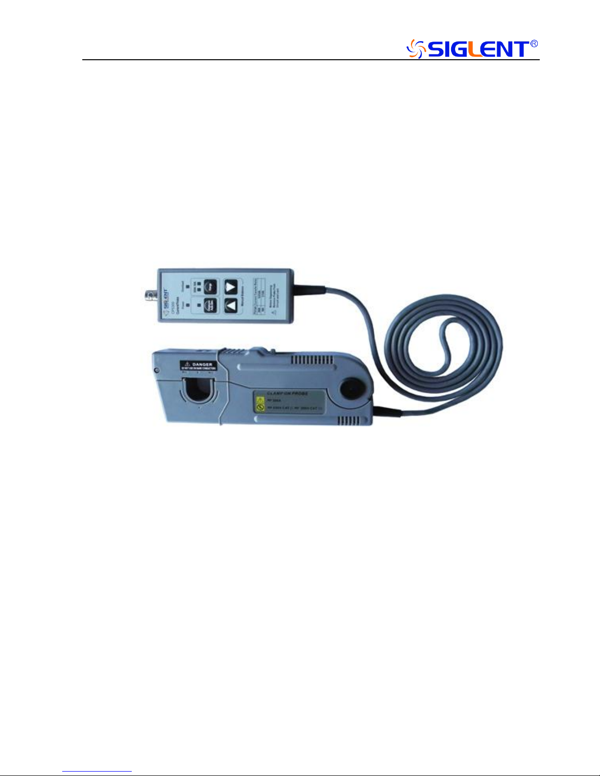
Description of Probe Parts
1)CP5300

7/15
1、Sensor head
This clamps the conductor being measured, and carries out the actual current
measurement. It is a precision assembly including a molded component, a ferrite
core,and a Hall effect element. It may be damaged if subjected to sudden
changes in ambient temperature, or mechanical strain of shock, and therefore
great care should be exercised in handling it.
2、Opening lever
Operating lever for opening the sensor head. Always use this lever to open the
sensor head.
3、BNC output connector
Connect to the BNC input connector of the oscilloscope. The output of the
current probe is terminated internally. You must select the input impedance of
the oscilloscope to be 1 MΩ in order to make accurate measurements. If the
oscilloscope you are using does not have a 1 MΩ input impedance setting you
can purchase 50 Ω to 1 MΩ adapter.
4、Power indicator LED
When the power adapter is plugged ,the green LED lights.

8/15
5、Overload indicator LED
When the current measured exceed the range,the red LED lights and the buzzer
alarms.
6、Degauss AutoZero indicator LED
When the key(Degauss AutoZero) pressed, this green LED lights. If
degaussing succeed,the buzzer well make double short sound. If degaussing
failed,the buzzer will make a long sound.
7、Range indicator LED
The green LED indicates the selected range.
8、Degauss AutoZero Key
When the key is pressed, the probe will be degaussing and AutoZero,about 5
secs.
9、Range selected Key
When the key is pressed, the probe will switch the range.
The CP5050 has two ranges(30A and 5A).The Current Transfer Ratio is 0.1V/A
and 1V/A.
The CP5300 has two ranges(150Aand 30A).The Current Transfer Ratio is
0.01V/A and 0.1V/A.
10﹑Offset (Up)Key
When the key is pressed, the offset increased.
11﹑Offset (Down)Key
When the key is pressed, the offset decreased.
12﹑Power plug
Connect this to the power adapter (DC 12V/1.2A).
13﹑Coarse adjustment trimmer
This adjustment should only be carried out if the probe offset is outside the
range of the zero adjustment dial.
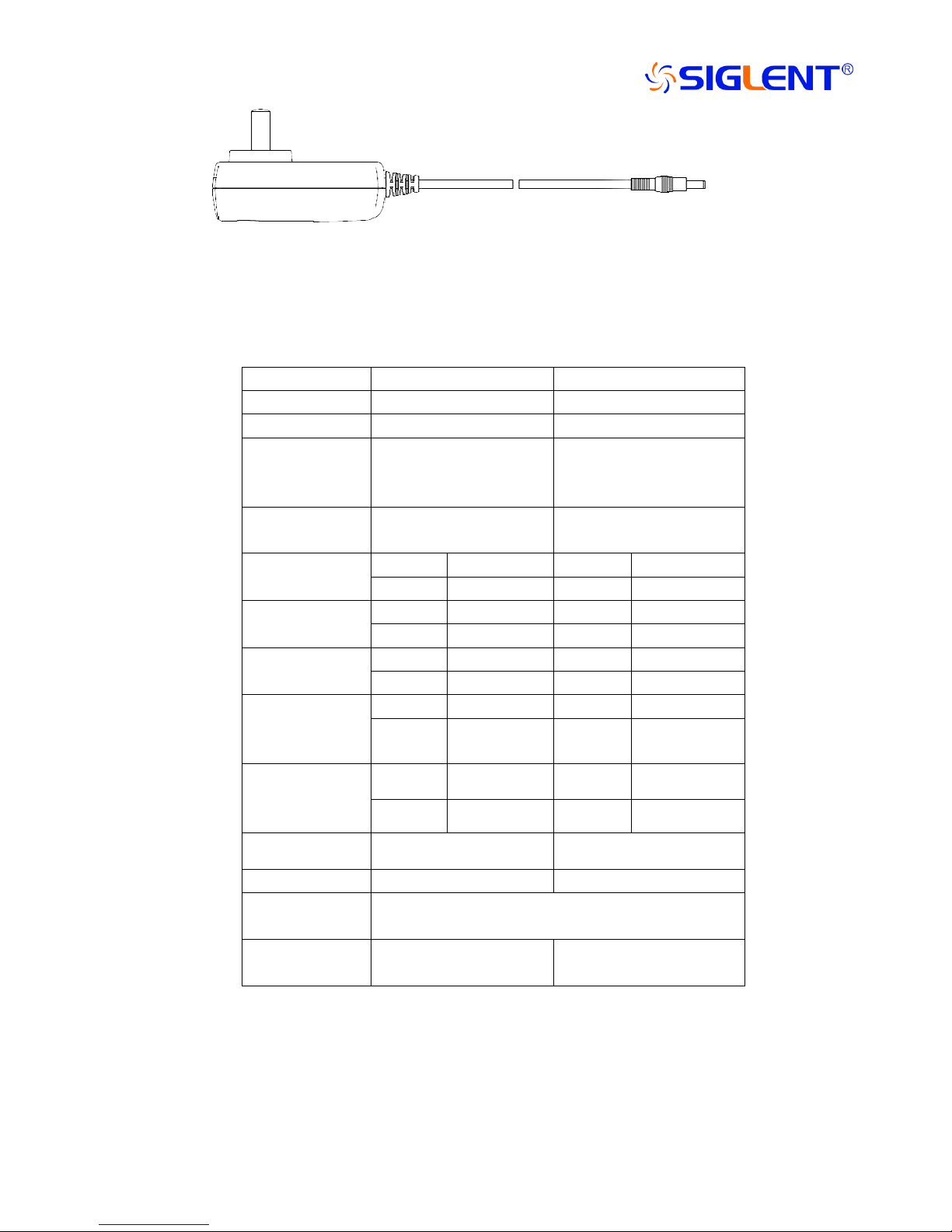
4)accessories
BNC Cable :50cm,MALE X MALE
9/15
Power Adapter (12V/1.2A)
Nominal and Typical Characteristics
Parameter
CP5050
CP5300
BW(-3dB)
DC-40MHz(see Fig.1)
DC-12MHz(see Fig.4)
Rise time
8.75ns or less
29ns or less
Continuous
maximum input
range
30Arms
(Frequency derating see
Fig.2)
150Arms
(Frequency derating see
Fig. 5)
Max peak
current value
50A
300A
Range
5A
1X
30A
10X
30A
10X
150A
100X
Over
5A
≥5A
30A
≥30A
30A
≥50A
150A
≥300A
Current Transfer
Ratio
5A
1V/A
30A
0.1V/A
30A
0.1V/A
150A
0.01V/A
Lowest
Measurable
Current
5A
1mA
30A
5mA
30A
10mA
150A
50mA
Amplitude
accuracy
(DC,45-66Hz )
5A
±1%±1mA
30A
±1%±10mA
30A
±1%±10mA
150A
±1%±100mA
Input impedance
see Fig.3
see Fig.6
Power Supply
DC 12V/1.2A
DC 12V/1.2A
Safety standards
IEC61010-1:2010 IEC61010-2-32:2012
EN61010-1: 2010 EN61010-2-32: 2012
Max. rated
voltage to earth
300V CAT I
600V CATII
300V CATIII
10/15
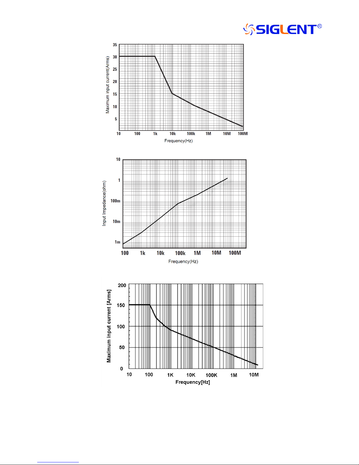
Fig.1 CP5050 Continuous maximum input rating (Frequency derating)
Fig.2 CP5300 Frequency response
Fig.3 CP5300 Continuous maximum input rating (Frequency derating)

11/15
Fig.4 CP5300 Input impedance VS Frequency
Mechanical Characteristics
Item
CP5050
CP5300
Measurement Conductor
Diameter Max.
5mm
20mm
CableLength
1m
1.5m
BNC Length
50cm
Adapter Dimensions
72*62*31mm
Clamp Dimensions
(L*W*H)
75*40*18mm
175*68*29mm
Termination Unit(L*W*H)
About 119*49*28mm
Probe Weight
240g
500g
Fig.10 Probe jaw dimensions
Environmental Characteristics
Item
CP5050
CP5300
Operating Temperature
0-40℃,80% or less

12/15
and Humidity
Nonoperating
Temperature and
Humidity
-10-50℃,80% or less
Operating Altitude
2000m
Nonoperating Altitude
12000m
Measurement Procedure
Attentions:
●The output of this unit is terminated internally. Use a high impedance input to the
measuring instrument. Accurate measurements are not possible when the input
impedance of the oscilloscope is set to 50 Ω. Besure to set the input impedance to 1
MΩ before making measurements.
●Immediately after powering on the probe, the probe maybe subject to an
appreciable offset drift due to the effect of self- heating. To counteract this, allow
the probe towarm up for about 30 minutes before carrying out measurement.
●When performing continuous measurements, it is necessary to be aware that the
offset voltage drifts, depending on factors such as the ambient temperature.
●Depending on the measured current frequency, some sound maybe produced by
resonance, but has no effect on measurements.
●The reading may be affected by the position within the clamp aperture of the
conductor being measured. The conductor should be in the center of the clamp
aperture.
●When carrying out a measurement, press the opening lever until the “UNLOCK”
indication disappears and check that the sensor head is properly closed. If the
sensor head is not properly closed, an accurate measurement is not possible.
●Accurate measurement may be impossible in locations subject to strong external
magnetic fields, such as transformers and high- current conductors, or in locations
subject to strong external electric fields, such as radio transmission equipment.
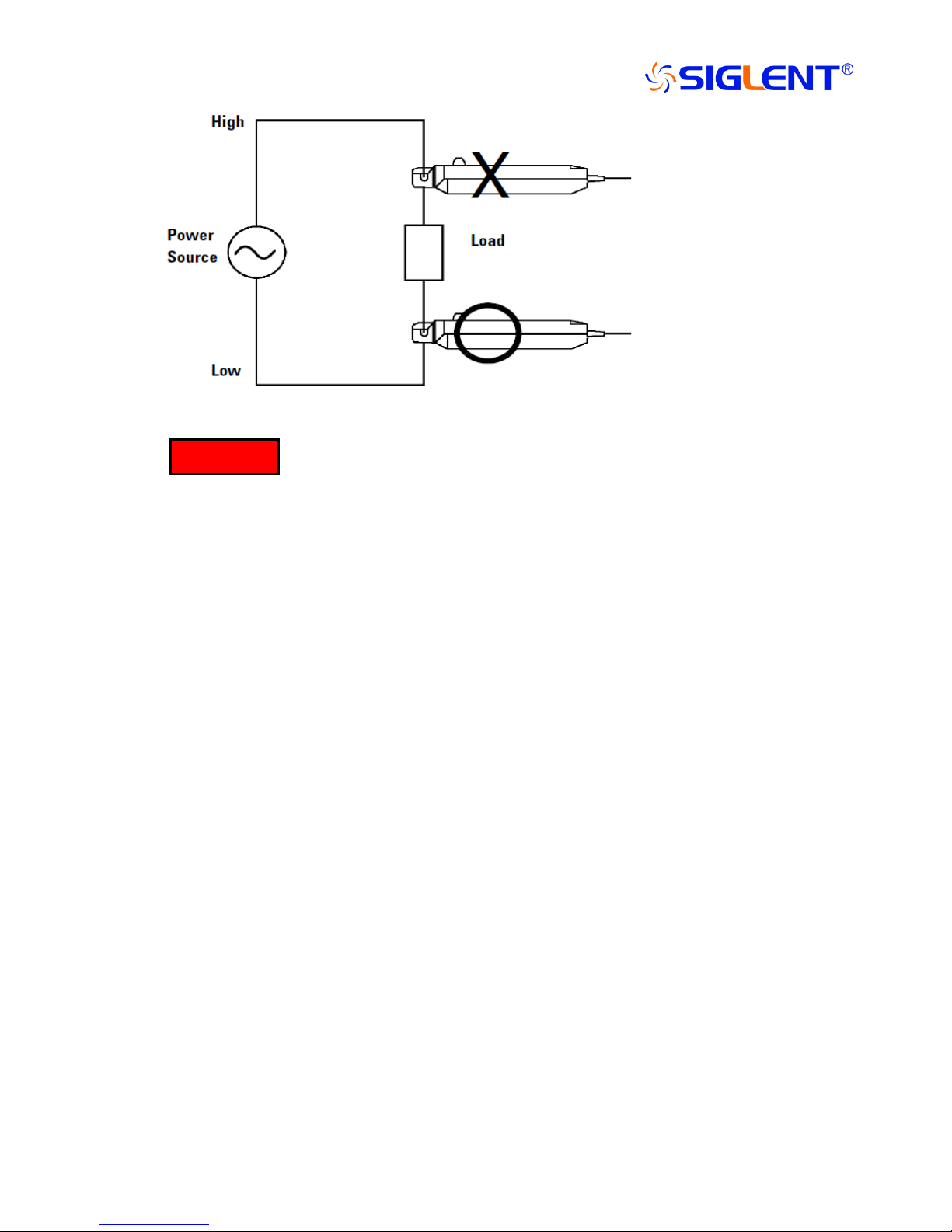
●At high frequencies, common mode noise may affect measurements taken on the
high voltage side of circuits. If this occurs, reduce the frequency range of the
waveform measuring instrument or clamp onto the low- voltage side of the circuit,
as appropriate.
Note
13/15
When disconnecting the output connector, be sure to release the lock, then pull the
connector. Forcibly pulling the connector without releasing the lock, or pulling on
the cable will result in damage to the terminator.
Do not demagnetize while the conductor being measured is clamped. This could
damage the components of the circuit being measured.
The maximum continuous input range is based on heat that is internally generated
during measurement. Never input current in excess of this level. Exceeding the
rated level may result in damage to the probe.
The maximum continuous input range varies according to the frequency of the
current being measured. See the figures in “Specifications”.
If excess current is input, generated heat activates a built- in safety function that
blocks normal output. If this happens, remove the input immediately (remove the
sensor from the conductor being measured or reduce the input current to zero). Wait
until the sensor has had sufficient time to cool before resuming operation.
Even if the input current does not exceed the rated continuous maximum,
continuous input for an extended period of time may result in activation of the
safety circuit to prevent damage resulting from heating of the sensor.
At high ambient temperatures, the built- in safety circuit may activate at current
input levels below the rated continuous maximum.
Continuous input of current exceeding the rated maximum or repeated activation of
the safety function may result in damage to the unit.
The probe is rated for maximum input under two conditions in addition to the input
WARNING

14/15
maximums shown in the “Characteristics ". Such as CP5050,these are (1) 30 Apeak
for continuous input and (2) 50 Apeak for pulse widths 10 μs. (1) indicates an upper
waveform response limit of 30 Apeak. Use the sensor at RMS current input levels
that are within the rated continuous maximums. (2) indicates the upper response
limit for a single input pulse.
When opening the sensor head of the probe, be sure to operate with the opening
lever. If an upper core is forced to open when the sensor head is locked, the open-
close mechanism can be damaged.
Preparations for Measurement:
1)Have the power supply and oscilloscope ready for waveform
measurement ready.
2)CP8000A series connects the power supply,the red LED lights.
Range select and Degauss AutoZero:
1)With the oscilloscope input at ground, adjust the trace to the zero position.
2)Set the input coupling of the oscilloscope to DC.
3)Connect the output connector of the current probe to the input connector of
the oscilloscope. Turn the collar until it clicks, and check that it is locked
securely.
4)Without clamping the conductor to be measured, press the opening lever
until the "UNLOCK" indication disappears, and check that the sensor
head is properly closed.
5)Select appropriate “Range”via the Range Key.
6)Press the “Degauss AutoZero”key, if succeed,continue to next step. If
failed,make sure the probe locked or other problems.
Making the Measurement:
1)Check that the system is safe and that the preparations described in the
preceding section have been carried out.

15/15
2)Pull the sensor opening lever with the sensor head opens.
3)Align the sensor so that the current direction indication corresponds to the
direction of current flow through the conductor to be measured. Also, align
the clamp so that the conductor is in the center of the sensor aperture.
4)Press the opening lever on the sensor head until the "UNLOCK"
indication disappears. Also check that the opening lever is firmly locked
and the sensor head securely closed.
Service Strategy
Problems
Possible cause
Processing methods
Can’t measuring DC
Power off
Power on
Oscilloscope setAC mode
Oscilloscope setAC mode
Sensor is not locked
Lock the sensor
Can’t adjust to zero
Sensor with magnetization
Demagnetization and Zero Adjustment
Zero Adjustment out of range
turn the
coarse adjustment trimmer
Measuring amplitude is
small in all frequency
Oscilloscope with 50Ω input
Oscilloscope with 1MΩabove input
List of goods
List of goods
name
quantity
PROBE
1
DC-12V/1.2A Adapter
1
Tool Bag
1
BNC Cable
1
Instruction Manual
1
Test Report
1
This manual suits for next models
1
Table of contents


