Energy GPV3KTL User manual

GPV 3KTL/4KTL/5KTL
>Single-Phase string inverters
Supports up to 150%DC/AC ratio
Fast installation with no led opening necessary
Dual MPPT for flexible installation
Small and light thanks to compact design
IP65 for outdoor use
Differernt color optons available

GPV 3KTL/4KTL/5KTL
GPV5KTL
7500Wp STC
5500VA
5000W
23A
Features
DC connection
AC connection
Mounting type
LED indicators(state/fault/communication)
Communication:RS485/wifi/GPRS
Certification and approvals(more can be provided on demand)
Plug-and-play connectors
Wall-mounted
CE,EN50549,G98/99,VDE-AR-N4105,AS/NZS 4777,C10/C11,VFR2014&
UTE C15,IEC62109,IEC62116,IEC61727,IEC61683,IEC60068,IEC61000
Technical data
DC Input
Max.PV array power
Max. input voltage
MPP voltage range/rated input voltage
Min. input voltage
Initial feed-in voltage
Max. operetion input current per MPPT
Max. short circuit current per MPPT /Per string input
Number of independent MPPT inputs/strings per MPPT input
AC Output
Rated power
Max.apparent AC power
AC nominal voltage
AC voltage range
AC grid frequency/Range
Rated grid frequency/Rated grid voltage
Max. output current
Power factor adjustable range
Power factor at rated power
Number of feed phase
Harmonic distortion(THD)at rated output
Protective devices
Input-side disconnection device
Ground fault monitoring/Grid monitoring
DC reverse polarity protection/AC short circuit current capability
All-pole-sensitive residual-current monitoring unit
Protection class(IEC 62109-1)/Overvoltage category(IEC 62109-1)
Efficiency
Max.efficiency/European efficiency
General parameters
Dimentions(W/H/D)
Weight
Operating temperature range
Noise emission(typical)
Self-consumption(At night)
Topological structure
Cooling concept
Degree of protection(IEC 60529)
Climatic category(IEC 60721-3-4)
Max. permissible value for relative humidity(Non-condensing)
Max. operating altitude
GPV3KTL
4500Wp STC
3000W
3300VA
15A
97.5%/96.5% 97.5%/97
/ /
GPV4KTL
6000Wp STC
550V
80~550V/360V
80V
100V
12A/12A
18A/18A
2/1
4400VA
4000W
220V/230V/240V
180~290V
50Hz/45Hz~55Hz ;60Hz/55Hz~65Hz
50Hz/230V
20A
1
0.8leading~0.8lagging
1
<3%
12kg
380/350/155mm
-25℃...+60℃
<25dB(A)
<1W
No transformer
Natural convection
IP65
4K4H
100%
3000m
97.5%/96.8%
I/AC:III;DC:II
/
/
Standarded features Optional features
1)Zero export installations supported with 2-pin RS485 for connection to approved smart meters.
2)DRED supported with RS485 communication for Australia & New Zealand.

Table of Contents
1 Notes on this Manual.............................................................................................1
1.1 General Notes...................................................................................... 1
1.2 Area of validity..................................................................................... 1
1.3 Target group......................................................................................... 1
1.4 Symbols used in this manual.......................................................... 2
2 Safety......................................................................................................................... 3
2.1 Intended use......................................................................................... 3
2.2 Important safety information........................................................... 4
2.3 Symbols on the label..........................................................................6
3 Unpacking.................................................................................................................7
3.1 Scope of delivery................................................................................ 7
3.2 Checking for transport damage...................................................... 8
4 Mounting................................................................................................................... 8
4.1 Requirements for mounting............................................................. 8
4.2 Mounting the inverter.......................................................................10
5 Electrical Connection.......................................................................................... 14
5.1 Safety....................................................................................................14
5.2 System layout of units without integrated DC switch.............15
5.3 Overview of the connection area.................................................. 15
5.4 AC connection................................................................................... 16
5.4.1 Conditions for the AC connection......................................................... 16
5.4.2 Grid connection........................................................................................ 20

5.4.3 Second protective grounding connection.............................................22
5.5 DC Connection...................................................................................22
5.5.1 Requirements for the DC Connection.................................................. 23
5.5.2 Assembling the DC connectors............................................................. 23
5.5.3 Disassembling the DC connectors........................................................25
5.5.4 Connecting the PV array........................................................................ 26
5.6 Conmunication equipment connection.......................................27
5.6.1 Mounting the WiFi or GPRS Stick......................................................... 27
5.6.2 Connect the network cable.....................................................................28
5.6.3 Connect the smart meter cable............................................................. 30
6 Communication.....................................................................................................31
6.1 System monitoring via RS485/ Ethernet..................................... 31
6.2 System monitoring via WLAN........................................................32
6.3 Inverter demand response modes (DRED)................................ 33
6.4 Active power control with Smart meter...................................... 34
6.5 Earth fault alarm................................................................................ 35
7 Commissioning..................................................................................................... 35
7.1 Electrical checks............................................................................... 35
7.2 Mechanical checks........................................................................... 36
7.3 Safety code check.............................................................................36
7.4 Start-Up................................................................................................36
7.5 Overview of the panel...................................................................... 37
8 Disconnecting the Inverter from Voltage Sources...................................... 38
9 Technical Data.......................................................................................................39
9.1 DC input data......................................................................................39
9.2 AC output data................................................................................... 40

9.3 General data....................................................................................... 41
9.4 Safety regulations.............................................................................42
9.5 Efficiency.............................................................................................43
9.5.1 Efficiency curve (GPV3KTL).................................................................. 43
9.5.2 Efficiency curve (GPV3.6KTL)............................................................... 44
9.5.3 Efficiency curve (GPV4KTL).................................................................. 44
9.5.4 Efficiency curve (GPV5KTL).................................................................. 45
9.6 Power reduction................................................................................ 45
9.6.1 Power reduction with increased ambient temperature (GPV3KTL).46
9.6.2 Power reduction with increased ambient temperature (GPV3.6KTL)
.............................................................................................................................. 46
9.6.3 Power reduction with increased ambient temperature (GPV4KTL).47
9.6.4 Power reduction with increased ambient temperature (GPV5KTL).47
9.7 Tools and torque............................................................................... 48
10 Troubleshooting................................................................................................. 49
11 Maintenance........................................................................................................ 51
11.1 Cleaning the contacts of the DC switch................................... 51
11.2 Cleaning the heat sink...................................................................51
12 Recycling and disposal.................................................................................... 53
13 EU Declaration of Conformity.........................................................................53
14 Warranty............................................................................................................... 53
15 Contact..................................................................................................................54


1
1 Notes on this Manual
1.1 General Notes
Gsmarte inverter is a transformerless solar inverter with independent MPP tracker.
It converts the direct current (DC) from a photovoltaic (PV) array to grid-compliant
alternating current (AC) and feeds it into the utility grid.
1.2 Area of validity
This manual describes mounting, installation, commissioning and maintenance of the
following Gsmart inverters:
GPV3KTL
GPV3.6KTL
GPV4KTL
GPV5KTL
1.3 Target group
This manual is for qualified electricians only, who must perform the tasks exactly as
described.
All persons installing inverters must be trained and experienced in general safety
which must be observed when working on electrical equipment. Installation personnel
should also be familiar with local requirements, rules and regulations.
Qualified persons must have the following skills:
• Knowledge of how an inverter works and is operated
• Training in how to deal with the dangers and risks associated with installing,
repairing and using electrical devices and installations
• Training in the installation and commissioning of electrical devices and installations
• Knowledge of all applicable laws, standards and directives
• Knowledge of and compliance with this document and all safety information

2
1.4 Symbols used in this manual
The safety precautions and general information are used in this manual as follows:
DANGER indicates a hazardous situation which, if not avoided, will result in
death or serious injury.
WARNING indicates a hazardous situation which, if not avoided, can result in
death or serious injury.
CAUTION indicates a hazardous situation which, if not avoided, can result in
minor or moderate injury.
NOTICE indicates a situation which, if not avoided, can result in property
damage.
INFORMATION that is important for a specific topic or goal, but is not
safety-relevant.

3
2 Safety
2.1 Intended use
1. Gsmart inverter converts the direct current from PV array into grid-compliant
alternating current.
2. The product is suitable for indoor and outdoor use.
3. The product must only be operated with PV arrays (PV modules and cabling) of
protection class II, in accordance with IEC 61730, application class A. Do not
connect any sources of energy other than PV modules to the inverter.
4. PV modules with a high capacitance to ground must only be used if their coupling
capacitance is less than 1.0μF.
5. When the PV modules are exposed to sunlight, a DC voltage is supplied to this
equipment.
6. All components must remain within their permitted operating ranges at all times.
7. The product is also approved for the Australian market and may be used in
Australia. If DRM support is specified, the inverter may only be used in conjunction
with a Demand Response Enabling Device (DRED). This ensures that the inverter
implements the commands from the grid operator for active power limitation at all
times. The inverter and the Demand Response Enabling Device (DRED) must be
connected in the same network and the inverter communication interface must be
activated.
8. When designing a PV system, ensure that the values comply with the permitted
operating range of all components at all times.

4
2.2 Important safety information
Danger to life due to electric shock when live components or cables are
touched
• All work on the inverter must only be carried out by qualified personnel who
have read and fully understood all safety information contained in this manual.
• Do not open the product.
• Children must be supervised to ensure that they do not play with this device.
Danger to life due to high voltages of the PV array
When exposed to sunlight, the PV array generates dangerous DC voltage which is
present in the DC conductors and the live components of the inverter. Touching
the DC conductors or the live components can lead to lethal electric shocks. If you
disconnect the DC connectors from the inverter under load, an electric arc may
occur leading to electric shock and burns.
• Do not touch non-insulated cable ends.
• Do not touch the DC conductors.
• Do not touch any live components of the inverter.
• Have the inverter mounted, installed and commissioned only by qualified
persons with the appropriate skills.
• If an error occurs, have it rectified by qualified persons only.
• Prior to performing any work on the inverter, disconnect it from all voltage
sources as described in this document(see Section 8 "Disconnecting the Inverter
from Voltage Sources").

5
Risk of injury due to electric shock and fire caused by high leakage
current
• The inverter must be reliably grounded in order to protect property and
personal safety.
Risk of injury due to electric shock
Touching an ungrounded PV module or array frame can cause a lethal electric
shock.
• connect and ground the PV modules, array frame and electrically conductive
surfaces so that there is continuous conduction.
• Do not ground any of the terminals of the strings.
Risk of injury due to hot heat sink
• The heat sink may get hot during operation. Do not touch!
Damage to the inverter due to electrostatic discharge
•Touching electronic components can cause damage to or destroy the inverter
through electrostatic discharge.
• Ground yourself before touching any component.

6
2.3 Symbols on the label
Symbol
Explanation
Beware of a danger zone.
This symbol indicates that the product mus be additionally grounded if additional
grounding or equipotential bonding is required at the installation site.
Beware of high voltage and operating current.
The inverter operates at high voltage and current. Work on the inverter must only
be carried out by skilled and authorized electricians.
Beware of hot surfaces.
The inverter can get hot during operation. Avoid contact during operation.
Do not dispose of this inverter with household waste.
For more information on disposal, please refer to Section 13 “Recycling and
disposal”.
CE mark.
The inverter complies with the requirements of the applicable EC guidelines.
Certification mark.
The product has been tested by TUV and got the quality certification mark.
RCM Mark.
The product complies with the requirements of the applicable Australian
standards.
Capacitors discharge.
Before opening the covers, the inverter must be disconnected from the grid and
PV array. Wait at least 5 minutes to allow the energy storage capacitors to fully
discharge.
Observe the documentation.
Observe all documentation supplied with the product.

7
3 Unpacking
3.1 Scope of delivery
Object
Description
Quantity
A
Inverter
1 piece
B
Wall mounting bracket
1 piece
C
Mounting accessory kit:
Wall anchors and hexagon bolts (3×)
M4×10 mm screw (2×)
1 set
D
DC connector
2 pairs
E
AC Plug connector
1 piece
F
WLAN (optional)
1 piece ( optional )
G
Magnetic ring
1 piece
H
Documentation
1 set
I
Smart meter terminal
1 piece
J
(optional)
1 set( optional )
A
B
C
D
E
F
G
H
I
J
Carefully check all of the components in the carton. If anything is missing, contact
your dealer.

8
3.2 Checking for transport damage
Thoroughly inspect the packaging upon delivery. If you detect any damage to the
packaging which indicates the inverter may have been damaged, inform the
responsible shipping company immediately. We will be glad to assist you if required.
4 Mounting
4.1 Requirements for mounting
Danger to life due to fire or explosion
Despite careful construction, electrical devices can cause fires.
• Do not mount the inverter on flammable construction materials.
• Do not mount the inverter in areas where flammable materials are stored.
• Do not mount the inverter in areas where there is a risk of explosion.
1. Be sure the inverter is installed out of the reach of children.
2. Mount the inverter in areas where it cannot be touched inadvertently.
3. Ensure good access to the inverter for installation and possible service.
4. Make sure that heat can dissipate, observe the following minimum clearance to
walls, other inverters, or objects:
5. The ambient temperature is recommended
below 40°C to ensure optimal operation.
6. Recommend to mount the inverter under the shaded site of the building or mount
an awning above the inverter.
Direction
Min. clearance(mm)
above
500
below
500
sides
300

9
7. Avoid exposing the inverter to direct sunlight, rain and snow to ensure optimal
operation and extend service life.
8. The mounting method, location and surface must be suitable for the inverter's
weight and dimensions.
9. If mounted in a residential area, we recommend mounting the inverter on a solid
surface. Plasterboard and similar materials are not recommended due to audible
vibrations when in use.
10. Do not put any objects on the inverter,Do not cover the inverter.
11. Mount the inverter vertically or tilted backward by a maximum of 15°.

10
12. Never mount the inverter tilted forward or sideways.
13. Never mount the inverter horizontally.
14. Mount the inverter at eye level to make it easy to operate and to read the display.
15. The electrical connection area must point downwards.
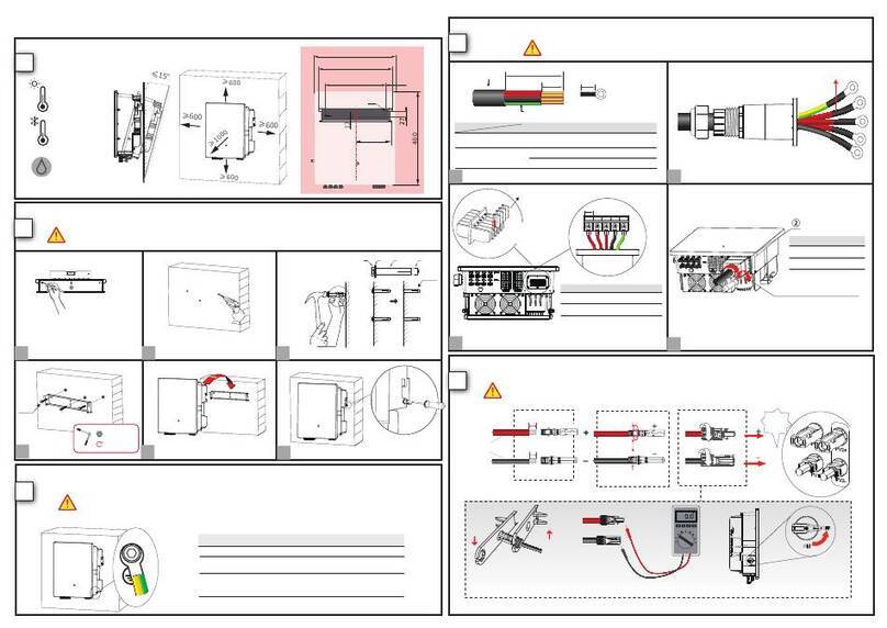
4.2 Mounting the inverter
Risk of injury when lifting the inverter, or if it is dropped
The weight of Solplanet inverter is max. 12 kg. There is risk of injury if the inverter
is lifted incorrectly or dropped while being transported or when attaching it to or
removing it from the wall bracket.
• Transport and lift the inverter carefully.
Mounting procedures:

11
Risk of injury due to damaged cables
There may be power cables or other supply lines (e.g. gas or water) routed in the
wall.
• Ensure that no lines are laid in the wall which could be damaged when drilling
holes.
1. Use the wall bracket as a drilling template and mark the positions of the drill holes.
Drill 3 holes with a 10 mm drill. The holes must be about 70 mm deep. Keep the drill
vertical to the wall, and hold the drill steady to avoid tilted holes.
Risk of injury due to the inverter falls down
•Before inserting the wall anchors, measure the depth and distance of the holes.
•If the measured values do not meet the hole requirements,redrill
the holes.
2. After drilling holes in the wall, place three screw anchors into the holes, then attach
the wall mounting bracket to the wall using the self-tapping screws delivered with the
inverter.

12
3. Holding the inverter and attach it tilted slightly downwards to the wall bracket.
4. Check both sides of the heat sink to ensure that it is securely in place.
5. Push the inverter as far as possible and attach it to both sides of the wall bracket

13
using the M4 screws.
If a second protective conductor is required in installation site, ground the inverter and
secure it so that it cannot drop from the housing (see section 5.4.3 “Second protective
grounding connection”).
Dismante the inverter in reverse order.

14
5 Electrical Connection
5.1 Safety
Danger to life due to high voltages of the PV array
When exposed to sunlight, the PV array generates dangerous DC voltage which
is present in the DC conductors and the live components of the inverter.
Touching the DC conductors or the live components can lead to lethal electric
shocks. If you disconnect the DC connectors from the inverter under load, an
electric arc may occur leading to electric shock and burns.
• Do not touch non-insulated cable ends.
• Do not touch the DC conductors.
• Do not touch any live components of the inverter.
• Have the inverter mounted, installed and commissioned only by qualified
persons with the appropriate skills.
• If an error occurs, have it rectified by qualified persons only.
• Prior to performing any work on the inverter, disconnect it from all voltage
sources as described in this document(see Section 8 "Disconnecting the
Inverter from Voltage Sources").
Risk of injury due to electric shock
• The inverter must be installed only by trained and authorized electricians.
• All electrical installations must be done in accordance with the National Wiring
Rules standards and all locally applicable standards and directives.
This manual suits for next models
3
Table of contents
Other Energy Inverter manuals
Popular Inverter manuals by other brands

Mitsubishi Electric
Mitsubishi Electric FR-A760 Series instruction manual

SUNLINK
SUNLINK Precision-Modular RMS Assembly instructions

Siel
Siel SOLEIL 3F-TL10K Installation and operation manual

FSP Technology
FSP Technology LightUp L8000 user manual

Haier
Haier 1U35MECFRA-3 Service manual

Larson Electronics
Larson Electronics HAL-SPK-2X150PNL-SCS-2X100AH-24-PLC instruction manual