Signal Audio Workshop Gainrider User manual

Gainrider Vacuum Tube
Dynamic Range Controller
OWNER’S MANUAL
Signal Audio Workshop
Abarbanel ST.53
Tel Aviv 66089 IsraelP.O.B 5169 TLV 61051Office: 972-3-6820892
Fax: 972-3-6824716
www.signal-audio.com

Gainrider Owner’s Manual
Content:
Preface ____________________________
Front Panel Controls __________________
Signal Chain ______________________________
Side Chain __________________________
RMS Detector ________________________
Crest Detector ____________________________
Tips & Tricks ____________________________
Installation _________________________
Maintenance & Calibration ________________
Gainrider PCB top view ______________________
Specifications _______________________
Warranty and Registration Form __________
3
4
5-6
6
7
7-8
8-9
9
10-11
12
13
14-15
www.signal-audio.com
2

Dear customer,
I am confident that working with the Gainrider
will open new worlds of manipulating audio
dynamics with a tool like no other. In order to
produce the full potential of this sophisticated tool I strongly
encourage you to read and understand this manual thoroughly.
I’d like to personally thank you for the confidence
that you have shown in Signal Audio Workshop
by purchasing the Gainrider. You acquired the
latest generation of dynamics processor which is
unequal in its design and specification.
At Signal Audio Workshop we consider the development and
assembly of our gear an art form and take great pride in the final
product. The Gainrider is a result of a five year development
period and 10 years of researching the dynamic behavior of music
and audio signals.
In an effort to innovate and achieve the Gainrider’s outstanding
capabilities we have revolutionized the SIDE CHAIN system with
unique features, superior reaction and accuracy that can provide
sophisticated dynamic range processing.
For the VCA circuitry we chose the VARIABLE BIAS topology for its
speed and superb sound performance. The same VCA topology
implemented in the legendary FAIRCHILD 670 and its close
relatives.
All the signal path stages are pure CLASS-A tubes circuitry and 3
transformers for each channel takes this uncompromising structure
to the highest level of sonic excellence.
I hope you will enjoy working with the Gainrider as much as we
enjoyed making it for you!
With Honor
Oded Levy
Signal Audio Workshop
3

Front Panel Controls
1. DC-T.H=DC-THRESHOLD: The input signal exceeded above this controlled
threshold level goes into compression.
2. LOG-RATIO: Being a variable bias compressor means that the ratio of the
signal being compressed gets higher with the amount of gain reduction.
Therefore this knob adjusts the ratio’s slope angle (from soft compression -
to hard limiting).
3. ATTACK time: Sets the time it will take the VCA’S RMS DETECTOR to
accomplish its desired compression.
4. RECOVERY time: Sets the time it will take the VCA’S RMS DETECTOR to
recover from compression.
5. CREST-LEVEL: In any regular compressor, having an attack time means
also that some amount of fast transients entered the VCA will not develop
gain reduction. The longer the RMS ATTACK the more short peak transients
missed by the VCA, for these purpose we implemented a CREST DETECTOR
that detects those peaks and allows you to mix them with the RMS signal
on its way to the VCA and you chose their level of mixing from 0% to
300% (why 300%? hear it ...)
6. CREST-RECOVERY: Enables you to give the CREST signal a private
recovery time.
7. OUT-LEVEL: Allows you to amplify the output level in order to makeup for
gain loses from compression.
8. IN-LEVEL: This is a variable input attenuator for both sides, ranging from
-20db to 0db, enables you to set compression amounts to both sides
simultaneously or altering the amount of signal to drive this tube
instrument.
9. BYPASS: It’s a HARD WIRED BYPASS switch for channel A.
10. ST-LINK: This switch engages both channels VCA signals for operating on
stereo signals (It still means that both sides need to be tuned equally).
11. MODE: This switch affects the signal path, it has two operations - NRM
MODE: both channels A and B are separate. This means, channel A is left
and B is right, or dual mono, (just like any other normal compressor). M.S.
MODE (used only with stereo signals): means that channel A is now
compressing the center of the stereo signal therefore it will be called L+R,
And channel B will compress the sides of the stereo signal therefore it will
be called L-R (as seen on front panel). The output levels unlike any other
compressor with M.S. mode, allows you to tune the level of the MONO
versus SIDES and controlling stereo image’s width.
12. GAIN REDUCTION Meter: Peak meter with 21 segments especially
designed to deflect these unique fast VCA movements.
4
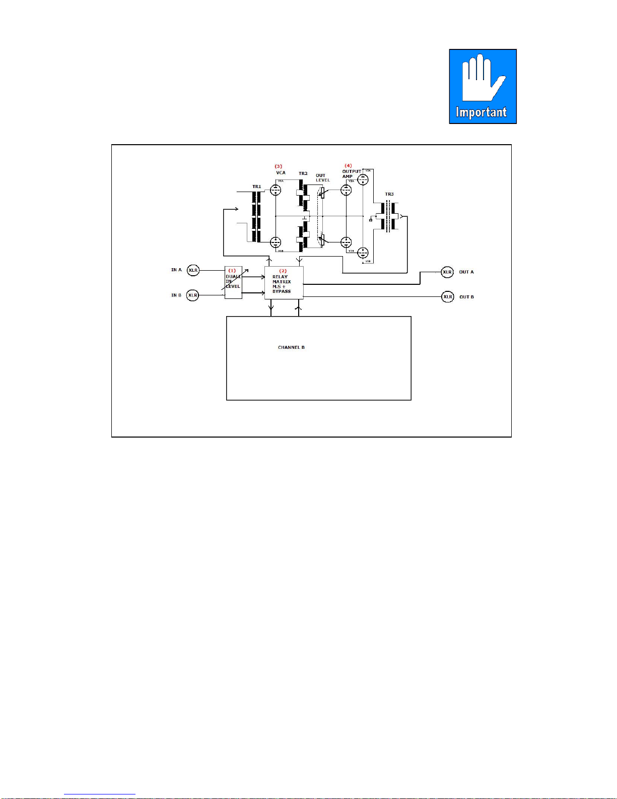
Signal Chain
This chapter details the signal chain structure in order
to help you better understand the Gainrider
capabilities.
(1) DUAL IN LEVEL:
This is a variable input attenuator for both sides, ranging from
-20db to 0db. It enables you to set compression amounts to
both sides simultaneously or altering the amount of signal to
drive into the Gainrider tubes.
(2) RELAY MATRIX:
The passive relay matrix is in charge of functions like:
BYPASS+M.S.\NORM modes. Carefully planed to preserve
signals quality at all operating modes.
(3) VCA STAGE:
The first stage of amplification is the VCA stage, made from two
custom wound transformers and 6BQ7 sharp cutoff tube. An
inter-stage transformer is essential in order to reach high speed
gain reduction capabilities with minimum artifacts.
5

(4) OUTPUT AMPLIFIER:
The output amplifier is made from 12AX7 and 6CG7 tubes that
drive the output transformer. This stage supplies the makeup
gain needed and drives the output transformer.
The over sized custom wound output transformer is designed to
supply the unit’s line output power needed with maximum
signal integrity, especially when it comes to low frequency
T.H.D.
All signal stages are internally balanced with Tube class-
A topology.
Side chain
The SIDE CHAIN circuitry is pure solid state in order to achieve the
precision and speed needed for the Crest Detection.
Looking at the block diagram you can see that at some point after the
Ratio amp, the signal splits into two paths. One is the RMS signal
path (4), with functions like ATTACK and RELEASE, while the other is
the CREST which forms in the COMPARATIVE DETECTOR stage (6).
Then it goes to a second detector that sets the timing of the CREST
material (CREST REL) (7).
Next, there is the blending process back with the RMS material where
the CREST LEVEL determines the CREST amount.
We implemented the 0-300% scale on the CREST LEVEL knob in
order to enable high levels of CREST material to mix with the RMS. In
this instance, the Gainrider can generate a rhythmic effect caused by
CREST signals taking control over the slow movements of the RMS
material. This unique phenomena happens because the CREST
material is mostly originated from the peaks that forms the rhythm of
all conventional music.
6
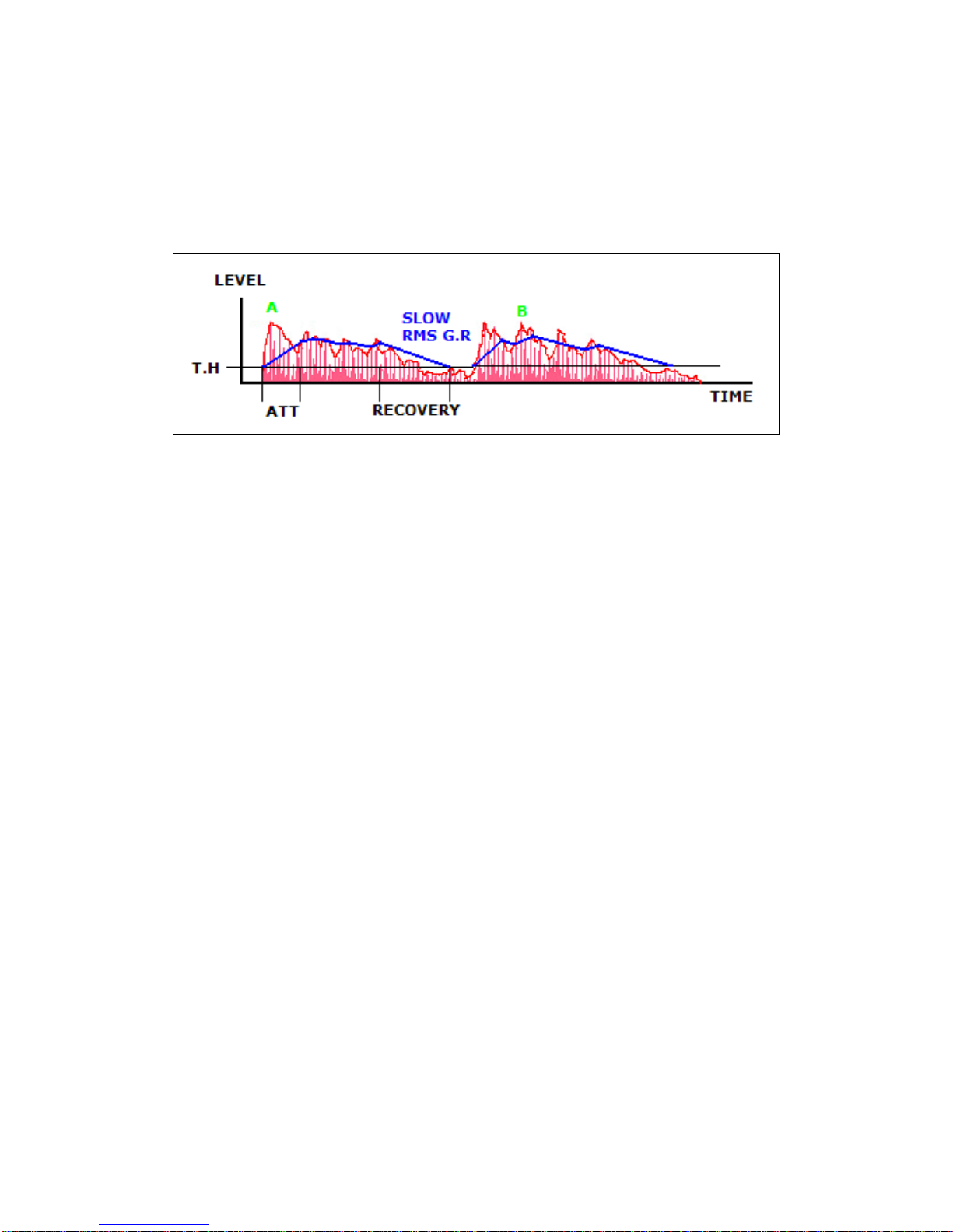
RMS Detector
In order to better understand the dynamic behavior of the Gainrider
we need to understand the way it is developing Gain reduction in
comparison to the input signals envelope.
The above drawing shows an envelope of signal before compression
(RED).
On the left we can see the Threshold level (Black line), two parts of
envelope exceed this level line, generating Gain Reduction (G.R. -
blue). As you can see the G.R. curve has Attack and Recovery times
effected by front panel settings.
The blue curve is called RMS SLOW G.R. curve, as being significantly
slower then envelopes rise and fall times This is the classic method of
compression used by conventional compressor/limiters.
Areas A and B (green), are fast transients that are too fast for the
RMS mechanism to notice. Those transients are called CREST
transients.
Conventional compressor/limiter does not offer a way to manipulate
crest material except for, maybe chopping the peaks with a limiter.
CREST Detector:
As seen on previous chapter there are a lot of fast envelope
movements that any conventional compressor can’t track while
configuring SLOW RMS compression.
We refer these movements as CREST material and its rise and fall
times are much faster then the RMS envelope. Therefore we
developed a special detector to detect the FAST CREST G.R.
7

The picture above shows in green the CREST material that exceeded
T.H. level. You can see that sometimes it is above the RMS level and
sometimes lower then RMS.
The CREST signal has a very short attack time and a manually tuned
recovery time which is significantly shorter then RMS recovery time.
Mixing the two signals into the VCA gives us much better control over
dynamic range transients that appears on music program material.
You can refer this type of processing as having a very fast
compressor and a slower one mixed together in such a way that the
fast movements are modulating the slow one or even ride on them,
Therefore the name Gainrider.
The results of such mechanism are a much more natural and musical
VCA’s behavior and with much more proximity then other tools.
Tips & Tricks
1. Tuning CREST LEVEL will be done only after the initial RMS
ATTACK & RECOVERY are tuned according to program material.
You should always remember that the CREST is a by-product of
the RMS G.R. therefore altering RMS changes also the amount of
CREST to be created. Therefore always start with tuning RMS
ATTACK and RELEASE and then add the CREST LEVEL as needed.
2. As a rule of thumb: when tuning Release time it is always better to
have the timing somehow reflect the rhythm of the processed
material.
This way the compression applied will have enough time to recover
from its last RMS Gain reduction.
3. When working in M.S. mode do not work with ST-LINK on, since
there isn’t any rhythmic connection between the two channels.
4. Widening or narrowing of stereo image can easily be done on M.S.
mode even without compression, with the tuning of the OUT-LEVEL
controls you can compare the results to bypass when switching
both channels simultaneously.
8

5. When using M.S. we strongly recommend you to further judge the
resulted material with phase meter and ST/MONO monitoring.
Installation:
1. Make sure that the unit operates on the correct mains voltage
(230/115 VAC) before applying mains voltage.
2. Always install this unit in a properly grounded environment.
3. Do not expose the unit to humidity or dusty environment.
4. Do not expose the unit to heat sources and unventilated places.
Connections:
All audio connections are transformer floating balanced through XLR
connectors with the following pin list:
Signal Audio Workshop is not responsible for
damages created by improper installation.
PIN 1 GND
PIN 2 HOT
PIN 3 COLD
9

Maintenance & Calibration
Cleaning:
Do not clean the unit with water or with water soaked cloth.
Cleaning is best made with dry dusting brush and vacuum cleaner.
Dust and moisture are the primer enemy of switches and contacts
within this unit. Avoiding them as much as you can will prolong the
unit’s life significantly.
Maintenance:
There are no user’s serviceable parts inside the unit.
Opening and servicing this unit by anyone who is not authorized Signal
Audio Workshop service technician will void the warranty.
We recommend replacement of vacuum tubes only when the unit has
proven to not function correctly and according to the type of problem
discovered.
We recommend replacing the VCA tube when VCA balance can no
longer be obtained, after replacing VCA tube a full calibration
procedure must be done.
VCA balance check and calibration is recommended to be preformed
once a year.
VCA Balance calibration:
Remove the top cover of the unit.
Connect the unit to mains voltage and allow it to worm up for 15
minutes.
Check with DC Voltmeter the voltage between TP1 and TP2 located on
the left side of the main board (see picture on page 12).
The voltage between these test points should be as close to 0V as
possible.
Calibrate the voltage for the lowest reading obtainable by tuning R22.
Repeat the same procedure for channel B with TP101 and TP102 and
R122.
Full calibration procedure:
Remove the top cover of the unit, Connect the unit to mains voltage
and allow it to worm up for 15 minutes.
1. Perform a VCA Balance calibration for both sides as previously
shown.
2. Preparations:
Tune the knobs on front panel on both channels by the following
order.
T.H., ATT, RECOVERY, OUT-LEVEL: fully clockwise.
10

RATIO, CREST LEVEL, CREST RECOVERY: fully counter
clockwise.
IN LEVEL: set to 12:00 o’clock. ST-LINK: off. BYPASS: IN.
3. Connect DVM between chassis ground and test point C-IN-A
located on left of main board. Turn trimmers P1 and P2 located
on S.C. pcb of channel A to get minimum readings TYPICAL
READING -0.8V.
Repeat the same procedure on channel B with test point C-IN-B
and its S.C. pcb.
4. Connect 1khz tone at -4dbm to line in of channel A.
5. VCA OFFSET calibration: Connect channel A output to DBM
METER.
Calibrate trim P2 on the S.C. pcb (on the right) channel A to a
drop of -2.5dbm of output level. Do the same on channel B to
match the overall gain of channel A ( if the tubes were ideally
symmetric then -2.5dbm drop will equal the gains between the
two sides if not then compensate to equal gain of A versus B ).
6. VCA GAIN calibration: Change the Oscillators output level to
-8 dbm.
Turn T.H. knob counter clockwise, turn IN LEVEL, RATIO fully
clockwise.
Compare the output level of channel A on the dbm meter when
the T.H. is fully clockwise versus fully counter clockwise &
calibrate trimmer P1 Channel A till you get a -18dbm drop of
output level when T.H. is fully counter clockwise.
Calibrate the G.R. meter to read -18db of G.R.
Repeat the procedure on channel B.
7. T.H.D. MAX calibration: Connect a T.H.D meter to I/O of
channel A.
Tune the oscillator’s level to get -18db of Gain reduction on the
same knob settings. Calibrate trimmers R17 on main board to
give minimum T.H.D. readings on -18db of G.R.
Repeat the same procedure on channel B with R117.
8. Check and re trim the VCA balance of both channels with no
input signal connected.
9. Symmetry check: Check the maximum output gain of both
channels again for symmetry (without G.R.). Fine tune and
equal between them if needed by slightly trimming P2 (VCA
offset) on S.C. pcb in one of the channels.
Fine tune the VCA gain (P1) if needed to obtain best symmetry
of measured G.R. between both sides.
Fine tune the G.R. meter’s reading if needed to obtain best
symmetry of G.R. reading. For the symmetry tunings it is
best to connect the oscillator to both sides Line in with a
paralleled feeding cable.
11
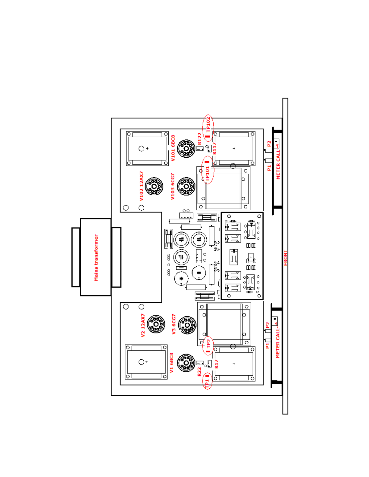
Gainrider PCB top View
12

Specifications:
Electronics:
Input Impedance: 10Kohms Balanced, (PIN 2 HOT)
Output Impedance: >500 ohms Balanced, (PIN 2 HOT)
MAX Gain: 28 db
MAX Input level: 36dbu for 1% THD (WITH NO GR)
MAX Output level: 32dbu for 1% THD (WITH NO GR)
Noise Floor: -91db @ 22-22khz typical
Distortion: @ Unity gain 1Khz +4dbu INPUT,
THD+N=0.058% (WITH NO GR)
Frequency Response: -/+1db from 20HZ to 20Khz
Attack Time: 0.2 to 70msec
Recovery Time: 0.07 to 2 sec
Operating Voltage: 230Vac @ 50Hz / 115Vac @ 60Hz
Power consumption: 40watts
Dimensions: H=3 Rack Units, W=19” ,D=13.4”
All spec’s at RL=600Ohm.
Info subject to change without prior notice.
© All legal rights reserved to Signal Audio Workshop.
From In to Out, as follows for each channel.
Signal chain:
All Tube & Transformer balanced Signal chain as
described bellow:
Transformer input, 1 dual Triode VCA Tube,
Inter stage Transformer, 2 dual Triode Output
driver, Output Transformer.
Integrated M.S Matrix for M.S Stereo imaging.
Side chain:
Solid state Side Chain security.
Special 21 segment G.R Peak Meter.
13

Limited Warranty
This product is warranted to the original consumer purchaser to be free from defects in
materials and workmanship under normal installation, use and service for a period of
one (1) year from the date of purchase as shown on the purchaser’s receipt.
The obligation of Signal Audio Workshop under this warranty shall be limited to repair
or replacement (at our option), during the warranty period of any part which proves
defective in material or workmanship under normal installation, use and service,
provided the product is returned to Signal Audio Workshop, TRANSPORTATION
CHARGES PREPAID. Products returned to us or to an authorized Service Center must
be accompanied by a copy of the purchase receipt. In the absence of such purchase
receipt, the warranty period shall be one (1) year from the date of manufacture. This
warranty shall be invalid if the product is damaged as a result of defacement, misuse,
abuse, neglect, accident, shipping damage destruction or alteration of the serial
number, improper electrical voltages or currents, repair, alteration or maintenance by
any person or party other than our own service facility or an authorized Service Center,
or any violation of instructions furnished by us. This one-year warranty is in lieu of all
expressed warranties, obligations or liabilities.
ANY IMPLIED WARRANTIES, OBLIGATIONS, ORLIABILITIES, INCLUDING BUT
NOT LIMITED TO THE IMPLIED WARRANTIES OF MERCHANTABILITY AND
FITNESS FOR A PARTICU-LAR PURPOSE, SHALL BE LIMITED IN DURATION TO
THE ONE YEAR DURATION OF THIS WRITTEN LIMITED WARRANTY. Some states
do not allow limitations on how long an implied warranty lasts, so the above limitation
may not apply to you. IN NO EVENT SHALL WE BE LIABLE FOR ANY SPECIAL,
INCIDENTAL OR CONSEQUENTIAL DAMAGES FOR BREACH OF THIS OR ANY
OTHER WARRANTY, EXPRESSED OR IMPLIED, WHATSO-EVER.
Some states do not allow the exclusion or limitation of special, incidental or
consequential damages so the above limitation or exclusion may not apply to you. This
warranty gives you specific legal rights, and you may also have other rights which vary
from state to state.
14

Warranty Registration Form
Please take the time to fill out this registration Form and send it to
the address mentioned below. Or send this page threw e-mail to:
Signal Audio WorkshopAbarbanel ST.53
Tel Aviv 66089 IsraelP.O.B 5169 TLV 61051
Fax: 972-3-6824716or send it by
Registering your product will allow you to get full warranty service
plus product upgrades if there will be any at the warranty period,
according to Warranty rules.
We would like to seize these opportunity to thank you once again for
choosing Signal AWS.
PRODUCT INFO:
Model: __________________________________________________
Serial No: ________________________________________________
Manufacturing date: ________________________________________
Supplier: _________________________________________________
OWNER INFO:
Owner’s name: ____________________________________________
Company: ________________________________________________
Address: _________________________________________________
City: ____________________________________________________
State: ___________________________________________________
Zip: _____________________________________________________
Country: _________________________________________________
Phone: ___________________________________________________
Fax: _____________________________________________________
e-mail: ___________________________________________________
Comments:
__________________________________________________________
__________________________________________________________
__________________________________________________________
______________________________________________________
15
Table of contents
Popular Music Equipment manuals by other brands

Fishman
Fishman VT POWERBRIDGE - ROUTING Template manual

Roland
Roland VT-12 Specifications

Fishman
Fishman M-200 PRO MANDOLIN PICKUP installation guide

Gemini
Gemini KL-1 Operation manual

Marshall Amplification
Marshall Amplification Haze MHZ15 owner's manual

Alien Apparatus
Alien Apparatus Solo Performer Show Controller user guide


Harley Benton
Harley Benton DNAfx bAss Mobile quick start guide

Zendrum
Zendrum Digital MIDI Controller owner's manual

Teac
Teac GT-R1 release note

Musicmakers
Musicmakers BALLAD HARP KIT Assembly instructions

PROEL
PROEL Axiom DSO480 user manual

Sweet Sound Electronics
Sweet Sound Electronics Mojo Vibe instruction manual