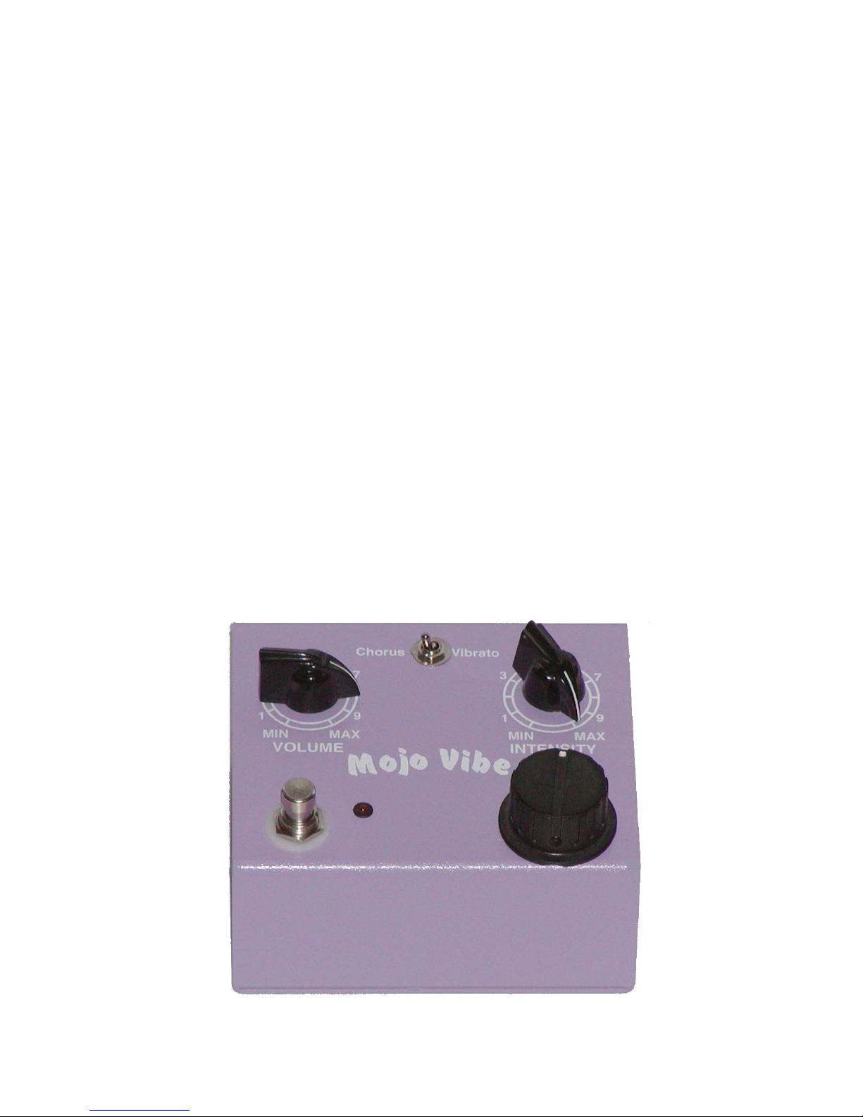
Sweet Sound Electronics Mojo Vibe User manual

Thank you for purchasing the
Sweet Sound Electronics, Inc.
Mojo Vibe
The absolute final word in vintage
Uni-Vibe type pedals!
Instruction manual

Rear Panel Jacks
1. Output – Output to amp or other effects in the
chain.
2. Input – Input from instrument, or output from
previous effect.
3. Power input – 2.1 mm barrel type connector
center negative polarity 9 volts DC. Absolutely
do not use more than 9.6 volts DC. There is
no advantage in trying to use a higher voltage
and it will damage the Mojo Vibe. The 9 volts
DC is converted to 18 volts internally and is
optimized for the high performance of the Mojo
Vibe.
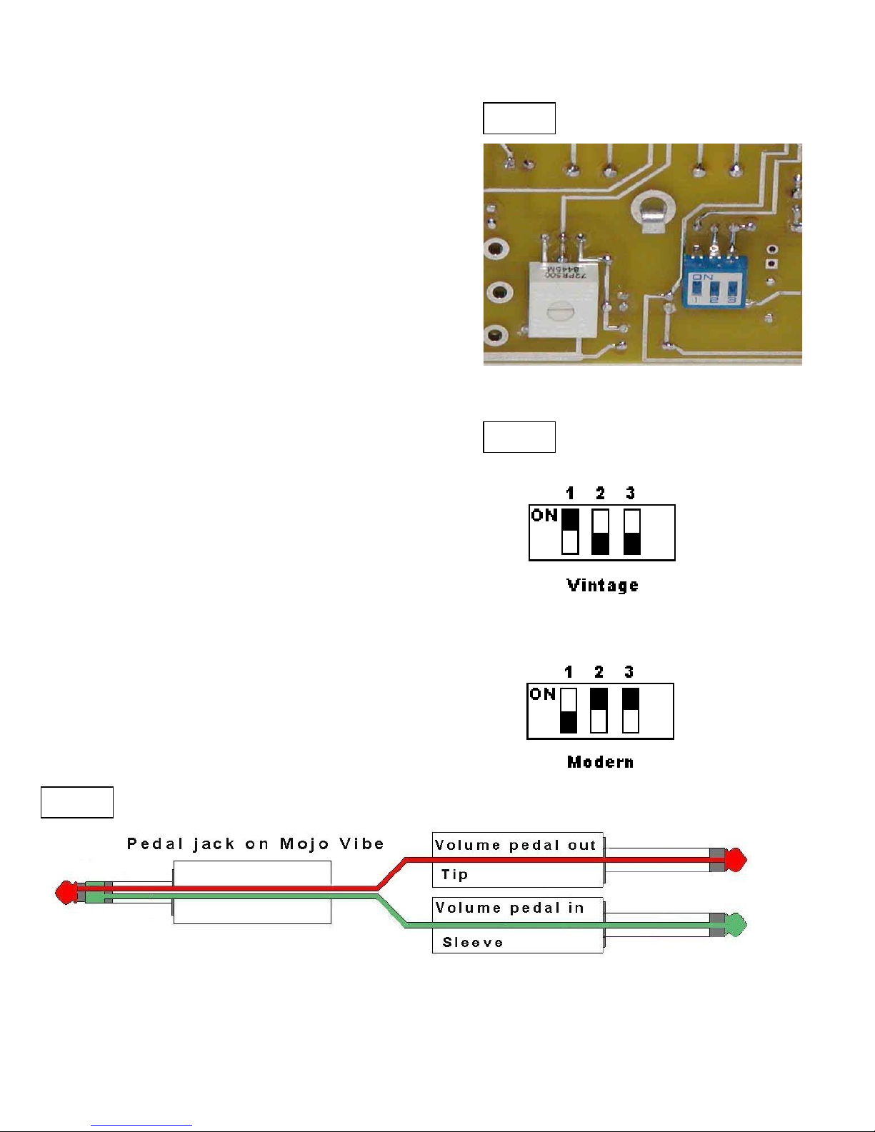
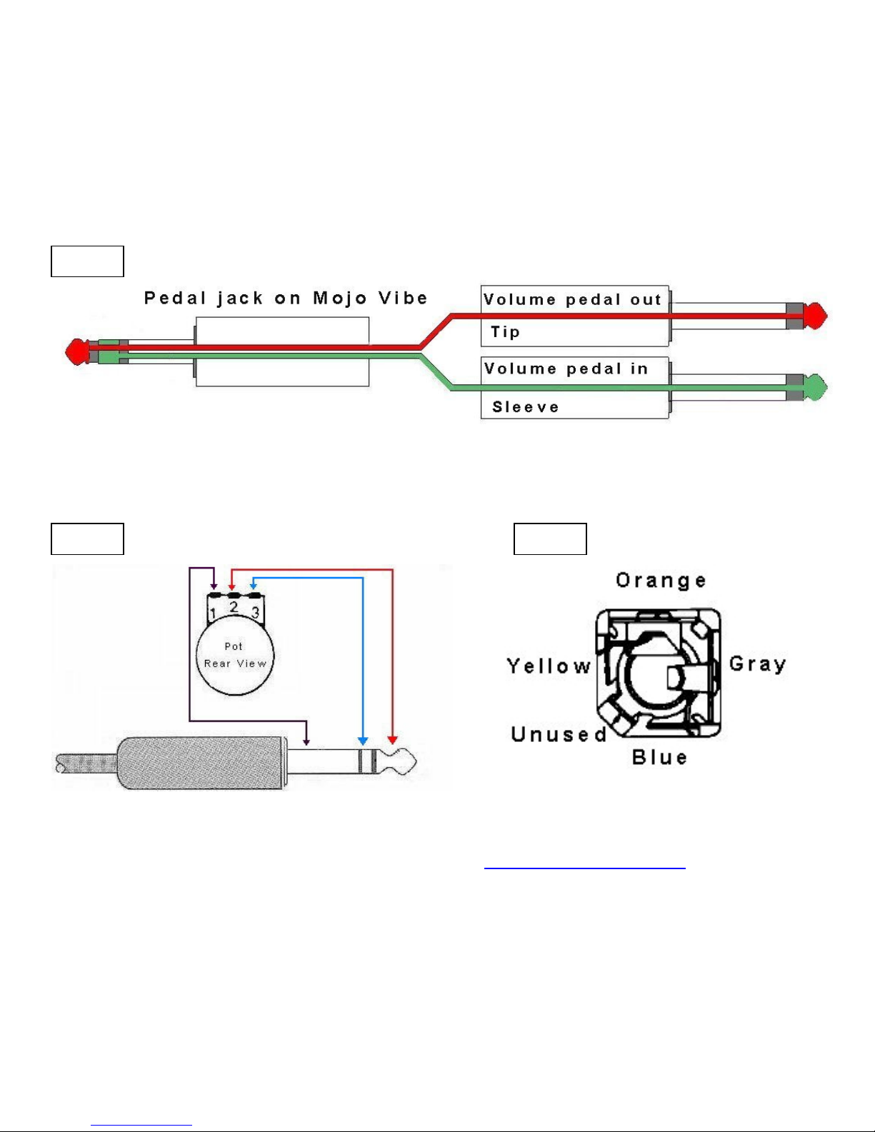
4. Pedal input – This used for an optional speed
pedal controller. Either one of the many
expression type pedals from Roland, Ensoniq,
MPM, Proel and others or with the use of a
channel insert cable (as used in mixing
consoles) you can use just about any passive
type volume pedal. More on this later…
Controls and Switches
5. Volume Control – Used to either match the
effect output with the unaffected bypassed
signal. Or to ad a slight boost to the affected
signal.
6. Chorus/Vibrato Switch – Selects between the
classic Uni-Vibe chorus sound or vibrato.
7. Intensity Control – Controls the depth or the
amount of the chorus or vibrato effect.
8. Bypass Switch – Switches the effect in and
out. The Mojo Vibe IS true bypass. Meaning
that when the effect is switched off it, the input
signal hardwired directly to the output jack. For
the most transparent bypass available.
9. LED Indicator – When the effect is engaged
the Led will light and also pulse to the speed set
by the speed control (#10). When off the effect
is bypassed.
10. Speed Control – This controls the speed of the
sweep in the Mojo Vibe. From slow rolling
phase to watery bubbling “Leslie” type sound.
The large oversized knob is used in an attempt
to make it easier for those who do not wish to
use the option of a pedal controller, to adjust it
with their foot. This knob when a control pedal
is used, so you have control over the total
speed range.is totally bypassed
Internal Switchable FET Buffer
The Mojo Vibe contains an active, internally
switchable Field Effect Transistor input buffer. Most
available “Vibes” that offer a “vintage” and “modern”
input switch use a input resistor switching circuit for
this purpose. The Mojo Vibe differs in that it uses
an active FET buffer to not only change the input
impedance but also buffers the input from the rest
of the circuitry for more clarity and high end
response. The reason the switch is internal as
12
34
5
6
7
8 9 10

opposed to mounted on the case is because it
produces a loud “pop” when switched and also to
save panel space. More than likely it will be a “set
and forget” setting, so this should not pose a
problem.
It is best to remove power to the Mojo Vibe before
switching the buffer mode. At least turn the amp
down, because it WILL pop. You can use your
finger nail or a ball point pen to switch the dip
switch. The modern setting will allow more high’s to
pass through the Mojo Vibe, which will produce a
brighter sound. The vintage setting is more like the
warm sound of the original 60’s Uni-Vibe.
Figure 1 shows the internal dip switch that is used
to switch between the different modes. (switch style
may vary)
Figure 2 shows the settings for the different modes
The Mojo Vibe is shipped in the vintage mode.
Using a passive volume pedal as a speed
controller
Figure 3 shows the cable type that is used when
using a standard “passive” type volume pedal. You
can construct these cables yourself or buy one of
the many brands available for use in channel
inserts with mixing consoles. A few quality cable
brands are the Proco YP series and the Hosa STP-
200 series. They are readily available at music
stores that carry mixing consoles or recording
equipment. Or many of the online music stores.
Fi
g
.1
Fi
g
. 2
Fi
g
. 3

Using an expression pedal as a speed
controller
Figure 4 shows the use of an expression pedal
like the ones used with keyboards. This is the
easiest method to use because of the single
cable used for connection. There are many
brands available that will work satisfactorily.
Try to look for a model that has impedance of
100 K. But others will work fine also. Keep in
mind that the external speed control option is
for effect. Not exact speed control.
Specifications
Dimensions –4.660 wide x 4.230 deep
Rear height 2.109
Front height 1.848
All measurements in inches
Weight -10 oz.
Input Impedance – Vintage mode 60 kil ohm
Modern mode 1 meg ohm
Current consumption – 20 – 50 ma. Max.
Case material -.080 Aluminum
Sweet Sound Electronics, Inc. 2003
www.sweetsound.com
1-954-971-7334
Fi
g
. 4

Serial numbers 001 – 038 were inadvertently sent out wired to use a
Yamaha/ Korg expression pedal. Which is not industry standard
wiring.
Using a passive volume pedal as a speed controller
Figure 3 shows the cable type that is used when using a standard “passive” type volume pedal. You
can construct these cables yourself or buy one of the many brands available for use in channel
inserts with mixing consoles. A few quality cable brands are the Proco YP series and the Hosa STP-
200 series. They are readily available at music stores that carry mixing consoles or recording
equipment. Or many of the online music stores.
Using an expression pedal as a speed controller
Figure 4 shows the use of an expression pedal like the ones used with keyboards. This is the easiest
method to use because of the single cable used for connection. There are many brands available that
will work satisfactorily. Try to look for a model that has impedance of 100 K. But others will work fine
also. Keep in mind that the external speed control option is for effect. Not exact speed control.
Figure 5 shows the wiring scheme of the pedal jack viewed from the rear of the jack.
Fi
g
. 4
Fi
g
. 3
Fi
g
. 5

Serial numbers from 039 on up, will be wired in the more standard configuration
as Roland and many other brands of expression pedals.
Figure 6 shows the hook up for a standard passive volume pedal with the standardized wiring. Note
the only major difference here is the mono ¼” plugs are reversed.
Figure 7 shows the standard wiring for an expression pedal as used with Roland and Boss products.
Figure 8 shows the standard wiring for the speed pedal jack on the Mojo Vibe as viewed from the
rear of the jack. (Serial #039 and up) This jack is a Switchcraft 114B switch.
If all this is too confusing and you would like me to rewire the pedal jack for you, I would be more than
(that is an “zero” in my email name, not an “oh” like it looks).
Sorry for any inconvenience this may have caused.
Fi
g
. 6
Fi
g
. 7 Fi
g
. 8
Table of contents