Signal NOXGEN III User manual

SIGNAL GROUP LTD
s/sales/masters/manuals/noxgman.doc Page 1of 17
SIGNAL NOXGEN III
NO2 CONVERTER TESTER
OPERATION MANUAL
NOX III/MAN
SIGNAL GROUP LTD
12 Doman Road
Camberley
Surrey
GU15 3DW
UK
Tel: +44(0) 1276 682841
Fax: +44(0) 1276 691302
e-mail: instruments@signal-group.com
site: www.signal-group.com

SIGNAL GROUP LTD
s/sales/masters/manuals/noxgman.doc Page 2of 17
COPYRIGHT
____________________________________________________________
All rights reserved. No part of this manual may be reproduced, stored in a retrieval
system or transmitted in any form or by any means -electronic, mechanical,
photocopying, recording or otherwise -without the prior written permission of The
Signal Group Ltd. While we believe that the information and guidance given in this
manual is correct, all parties must rely upon their own skill and judgement when making
use of it. The Signal Group Ltd. will not assume any liability to anyone for any loss or
damage caused by any error or omission in the manual, whether such omission is the
result of negligence or any other cause. Any and all such liability is disclaimed.
_____________________________________________________________
Issue Date Comments
108/85 First Issue
206/93 919
301/94 979
410/94 1045
502/99 1555
607/01 1740

SIGNAL GROUP LTD
s/sales/masters/manuals/noxgman.doc Page 3of 17
INDEX
PAGE
1.00 UNPACKING INSTRUCTIONS 3
2.00 INTRODUCTION 4
2.01 Principle of Operation 4
2.02 The Ozonizer 5
2.03 Flow Scheme Diagram 6
2.04 Remote Control Flow Scheme Diagram 7
3.00 INSTALLATION 8
3.01 General 8
3.02 Installation Drawing 9
3.03 Span Gas Connection 10
3.04 Oxygen/Air Inlet 10
3.05 Outlet 10
3.06 Mains Power 10
3.07 Remote Control Connections 11
4.00 OPERATION CONTROLS 12
4.01 Operation 13
4.02 Remote Control Operation 15

SIGNAL GROUP LTD
s/sales/masters/manuals/noxgman.doc Page 4of 17
1.00 UNPACKING INSTRUCTIONS
This instrument is packed for general freight purposes. It should withstand the
occasional “bumps and knocks” which occur during transit.
Please check the instrument for damage however, and report any damage within
24 hours to the factory or its Sales Office or Distributor.
1. Before any connection is made, unscrew the 4 cross head screws on
instrument cover lid.
2. Slide lid back to reveal the internal assemblies of the instrument.
NOTE: Do not take the cover off with power connected.
3. Check that all PCBs are firmly in their mating connectors on the front of
each PCB.
4. Check for any loose or broken parts which may have occurred during
transit.
5. Slide lid back and re-do the screws (do this before connecting power).
6. Read through the rest of this manual thoroughly and then carry out the
installation.

SIGNAL GROUP LTD
s/sales/masters/manuals/noxgman.doc Page 5of 17
2.00 INTRODUCTION
Chemiluminescent NOx analysers, such as Signal’s own Model 4000 Series; rely
upon the efficiency of the NO2 to NO converter in the analyser. The converter
enables a measurement to be made of the total oxides of nitrogen in the sample
stream (NOx = NO + NO2).
The 1979 Heavy Duty Register of the U.S. Environmental Protection Agency
stipulates that such converters must be checked before the analyser is initially
used, and thereafter at weekly intervals, to ensure that they have an efficiency of
at least 90%. The Signal NOXGEN III provides known, accurate amounts of NO2
for converter efficiency testing, and fully meets the EPA requirements.
The instrument is compact, inexpensive and provides a precision of control and
repeatability of results that were unobtainable with the previous generation of
converter testers. Ozone is generated by a high energy lamp using an electronic
pulse, which can be varied to adjust the Ozone level. The Noxgen III produces no
NO from air, in contrast to the high voltage corona discharge technique.
Stability against mains power variations, and the consequent effects of NO2
concentrations, is ensured by the incorporation of a voltage stabilised electronic
circuit, feeding pulses to a high voltage transformer.
2.01 PRINCIPLES OF OPERATION
The instrument is fed with nitric oxide and oxygen, the latter being subjected to a
high-energy lamp, which partially converts the oxygen to ozone. The
oxygen/ozone mixture is passed to the nitric oxide flow, and the nitric oxide is
instantly converted by the ozone to give nitrogen dioxide. The reaction between
the remaining oxygen and nitric oxide again produces nitrogen dioxide, but this
reaction is so slow that it does not need to be taken into account for test
purposes.
The amount of nitrogen dioxide generated is determined by measuring the fall of
nitric oxide concentration. If, for example, this concentration falls by 400 vpm,
then 400 vpm nitrogen dioxide has correspondingly been generated, as the
oxidation is a 1 : 1 molecular reaction. The concentration of nitrogen dioxide is
therefore directly proportional to the concentration of ozone generated. When
connected to the analyser converter, the NO2, should be converted back to NO.
From the results obtained the converter efficiency can be determined.

SIGNAL GROUP LTD
s/sales/masters/manuals/noxgman.doc Page 6of 17
2.02 THE OZONIZER
The signal Model NOXGEN III utilises a very efficient high energy lamp system
which ionises oxygen to ozone. The ozonizer is built into a fully self contained
enclosure within the instrument. This should not be opened by unauthorised
personnel because very high voltages exist within the enclosure, even with power
off.

SIGNAL GROUP LTD
s/sales/masters/manuals/noxgman.doc Page 7of 17
Figure 2.03 Flow Scheme Diagram

SIGNAL GROUP LTD
s/sales/masters/manuals/noxgman.doc Page 8of 17
Figure 2.04 Remote Control Flow Scheme Diagram.

SIGNAL GROUP LTD
s/sales/masters/manuals/noxgman.doc Page 9of 17
3.00 INSTALLATION
3.01 GENERAL
The Signal NOXGEN III comes in a 19” rack type, 3 units high enclosure. It can
be bench top used or fitted into a 19” rack console. For bench top use there are
extendible feet at the front which can be used to tilt the angle of the instrument
back for ease.
When using this instrument in a 19” rack, the feet will need to be removed. To do
this, undo the 4 cross-head screws on the under cover and slide back the cover
to remove it. With the cover removed you can easily unscrew the four feet before
replacing the cover for installation.
This instrument is fitted with Parker CP1 stainless steel tube fittings. Because of
the presence of nitric oxide, nitrogen dioxide and ozone, all of which are toxic
gases, great care should be taken to ensure that no leaks occur throughout the
tube work. Make the compression fittings off in accordance with the
manufacturers recommendations and do not over-tighten the nut.

SIGNAL GROUP LTD
s/sales/masters/manuals/noxgman.doc Page 10 of 17
Figure 3.02 Installation Diagram.

SIGNAL GROUP LTD
s/sales/masters/manuals/noxgman.doc Page 11 of 17
3.03 SPAN GAS CONNECTION
The span gas should be nitric oxide in nitrogen at a concentration about the level,
which you expect to use the analyser. The rear of the instrument has a 1/4”
compression fitting and you should use either Teflon (PTFE) or stainless steel
tubing. DO NOT USE NYLON OR COPPER TUBE.
Do not set the pressure to this line until you start to operate the instrument
because as soon as you set a pressure on the gas inlets, a flow will start to
occur.
3.04 OXYGEN/AIR INLET
Connect the oxygen or air cylinder to this connection, again using Teflon (PTFE)
or stainless steel tubing. It is most common to use oxygen but dry air can be
used with almost as high an ozone production as that using oxygen. Also, the
Signal Model NOXGEN III has been carefully designed so that no nitric oxide is
generated from the nitrogen in air, which means that converter efficiency testing
using air can still be done without inaccuracies. The only difference seen will be
the level of nitric oxide in the span gas which can be lowered in reading by
conversion to nitrogen dioxide, i.e. using air will allow you to change less NO to
NO2, using oxygen will allow you to change more NO to NO2.
3.05 OUTLET
This connection, again a 1/4” compression fitting, should have Teflon or stainless
steel tube connected to the calibration inlet port of the NOx analyser being
tested.
3.06 MAINS POWER
Connect a 220/240V or (110V if specified on rear panel nameplate) using a
properly grounded (earthed) supply. 1 amp is the MAXIMUM POWER
DEMAND.

SIGNAL GROUP LTD
s/sales/masters/manuals/noxgman.doc Page 12 of 17
3.07 REMOTE CONTROL CONNECTIONS
The remote control option is to enable you to control the gas selection functions
using TTL inputs. The TTL levels can be either OV inputs via the earth return
pins or, for people without a transistor logic controller or computer, a simple short
circuit wire link with a switch for ON and OFF can be connected between any of
the four earth pins and the function pin.
Before any of the function pins can be utilised, the remote enable must be
operated and again, either an OV logic signals via the earth return or a short
circuit wire link can be used.
Without the remote enable function being operated, the instrument operates in
the same way as the non remote control instrument.
With no power connected, the instrument with the remote control option will shut
off all gas flows using the built-in solenoid valves.
PIN NO. FUNCTION
(15 WAY D CONNECTOR)
1 N/C
2 OV RETURN
3 OV RETURN
4 OV RETURN
5 OV RETURN
6 OV RETURN
7 OV RETURN
8 N/C
9 N/C
10 REMOTE ENABLE
11 OXYGEN ON
12 SPAN ON
13 OZONE ON
14 N/C
15 N/C
NOTE:
DO NOT MAKE ANY CONNECTIONS TO N/C PINS
SIGNAL GROUP LTD
s/sales/masters/manuals/noxgman.doc Page 13 of 17
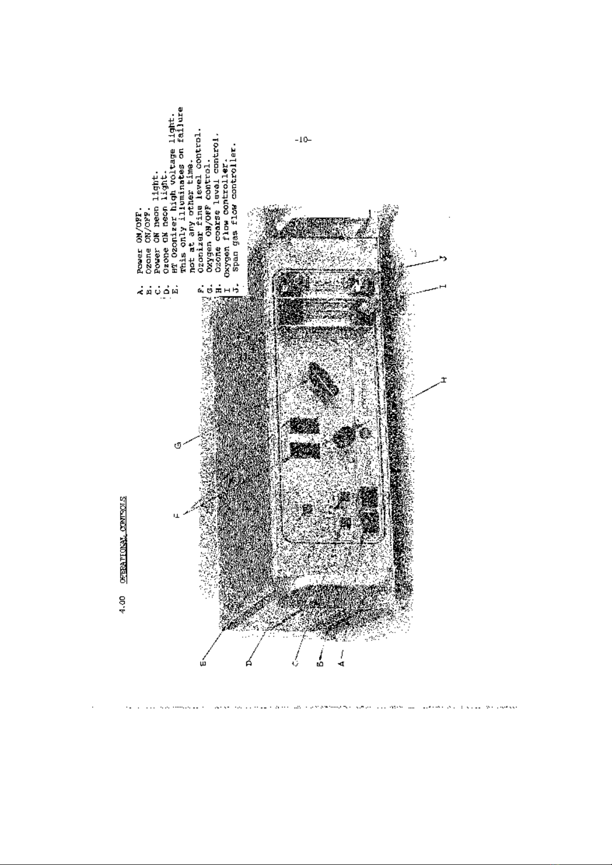
Figure 4.00 Operational Controls

SIGNAL GROUP LTD
s/sales/masters/manuals/noxgman.doc Page 14 of 17
4.01 OPERATION
WARNING:DO NOT LEAVE OZONE ON WITHOUT GAS FLOW
1. Ensure that all connections have been made in accordance with the
installation instructions.
2. Set 10 psig or 0.75 bar gauge (approx.) to regulators of both the span
gas and NO cylinder and the oxygen/air cylinder.
3. Balance the NO and NOx modes of your NOx analyser, ensuring they
both zero and span correctly. Select no mode.
4. Press the Power ON switch but not the Ozone switch at this stage.
5. Select OFF position for oxygen.
6. Adjust the span flow control to a suitable rate for your NOx analyser and
leave to settle until a suitable reading of the NO span gas is obtained on the
analyser.
7. Open the oxygen ON/OFF flow valve on the Noxgen front panel (G) and
adjust the flow of this oxygen using the flow control (I) until the analyser reading
falls by about 10% of the original reading in step 6. Record this reduced
reading (Reading A).
8. Switch on the ozone using the Ozone ON/OFF button B and adjust the
ozone level using both the coarse adjust switch (H) and the fine
thumbwheel adjust switches (F).
This adjustment should be made until the analyser reading is further
reduced so that it is now about 20% of the reading taken in Step 6. At
this stage the ozone in the Noxgen is converting the NO span gas to
NO2 and the fall in reading corresponds to the level of NO2 now being
generated. Whatever you do, always allow 10% of the reading in Step
6 (A) to remain. Record this new reading from the analyser (Reading B).
9. Having recorded a stable reading B, switch the analyser to the NOx
mode and wait for a steady reading. Record this reading (Reading C).

SIGNAL GROUP LTD
s/sales/masters/manuals/noxgman.doc Page 15 of 17
10. Switch off the Ozone and allow the NOx analyser reading to stabilise and
record this new reading (Reading D).
11. Shut off the oxygen flow valve on the front panel and observe the
analyser reading. This reading should now represent the same as
obtained in Step 6. The only difference now from Step 6, is that you
have the analyser in its NOx mode, and therefore any NO2 which was
in the span cylinder will produce a correspondingly higher reading
than at Step 6.
12. Calculate the efficiency using the equation:-
Efficiency = (A)
(D x C-B) x 100
( A -B )
if A = D i.e. (NO span = NOx span)
the equation simplifies to:-
Efficiency = (C -B) x 100
(A -B)

SIGNAL GROUP LTD
s/sales/masters/manuals/noxgman.doc Page 16 of 17
4.02 REMOTE CONTROL OPERATION
The remote control option (when fitted) has facilities to enable you to control the
following functions from remote either TTL or contact closure. See installation
instructions for details.
1. Remote enable control ON/OFF.
2. Remote oxygen ON/OFF.
3. Remote span gas ON/OFF.
4. Remote Ozone ON/OFF.
When using the remote control facilities you must firstly set the instrument’s flow
control and Ozone level manually, exactly the same as previously explained in the
Operation Section. Therefore, all the settings will be made manually before
going to remote control.
Unless the remote enable control is activated, the instrument will behave the
same as the standard manual controlled Noxgen and the operation as explained
in Steps 1-11 can be carried out as normal.
With power off, all solenoids will close and gas will be automatically shut off.
(This is not so with the remote control versions).
Having set up the Noxgen III in the normal way, to carry out remote control
converter test you simply follow the following steps:-
1. Switch power on.
2. Activate remote enable.
3. Activate span gas ON (Reading A).
4. Activate Oxygen gas ON (Reading B).
5. Activate Ozone On (Reading C).
6. Switch analyser from NO to NOx mode (Reading D).
7. Deactivate the Ozone (Reading E).
8. Deactivate the Oxygen gas.
NOTE: In order to allow complete remote control for this test, Signal
has designed their own Model 4000 chemiluminescent NOx
analyser, complete with remote controlled NO/NOx modes.

SIGNAL GROUP LTD
s/sales/masters/manuals/noxgman.doc Page 17 of 17
Figure 4.02 Chart Display
Table of contents


