Megger VLF Sinus User manual

VLF Sinus 34 kV
VLF Test System
USER GUIDE
Issue: A (05/2022) - EN
Article number: 128312971


3
Consultation with Megger
The present system manual has been designed as an operating guide and for reference. It is meant to answer your
questions and solve your problems in as fast and easy a way as possible. Please start with referring to this manual
should any trouble occur.
In doing so, make use of the table of contents and read the relevant paragraph with great attention. Furthermore,
check all terminals and connections of the instruments involved.
Should any question remain unanswered, please contact:
Megger Limited Megger Germany GmbH (Baunach)
Archcliffe Road
Kent CT17 9EN
T: +44 1304 502100
F: +44 1304 207342
E: uksales@megger.com
Dr.-Herbert-Iann-Str. 6
D - 96148 Baunach
T: +49 9544 68 – 0
F: +49 9544 22 73
E: team.dach@megger.com
Megger Germany GmbH (Radeburg) Megger USA
Röderaue 41
D - 01471 Radeburg / Dresden
T: +49 35208 84 – 0
F: +49 35208 84 249
E: team.dach@megger.com
Valley Forge Corporate Centre
2621 Van Buren Avenue
Norristown, PA 19403 USA
T: +1 610 676 8500
F: +1 610 676 8610
Megger
All rights reserved. No part of this handbook may be copied by photographic or other means unless Megger have before-hand
declared their consent in writing. The content of this handbook is subject to change without notice. Megger cannot be made
liable for technical or printing errors or shortcomings of this handbook. Megger also disclaim all responsibility
for damage resulting directly or indirectly from the delivery, supply, or use of this matter.

4
Terms of Warranty
Megger accept responsibility for a claim under warranty brought forward by a customer for a product sold by
Megger under the terms stated below.
Megger warrant that at the time of delivery Megger products are free from manufacturing or material defects which
might considerably reduce their value or usability. This warranty does not apply to faults in the software supplied.
During the period of warranty, Megger agree to repair faulty parts or replace them with new parts or parts as new
(with the same usability and life as new parts) according to their choice.
Megger reject all further claims under warranty, in particular those from consequential damage. Each component
and product replaced in accordance with this warranty becomes the property of Megger.
All warranty claims versus Megger are hereby limited to a period of 12 months from the date of delivery. Each
component supplied by Megger within the context of warranty will also be covered by this warranty for the
remaining period of time but for 90 days at least.
Each measure to remedy a claim under warranty shall exclusively be carried out by Megger or an authorized
service station.
To register a claim under the provisions of this warranty, the customer has to complain about the defect, in case of
an immediately detectable fault within 10 days from the date of delivery.
This warranty does not apply to any fault or damage caused by exposing a product to conditions not in accordance
with this specification, by storing, transporting, or using it improperly, or having it serviced or installed by a
workshop not authorized by Megger. All responsibility is disclaimed for damage due to wear, will of God, or
connection to foreign components.
For damage resulting from a violation of their duty to repair or re-supply items, Megger can be made liable only in
case of severe negligence or intention. Any liability for slight negligence is disclaimed.

5
Contents
1Safety Advices............................................................................................................... 6
1.1 General Notes ............................................................................................................................6
1.2 General Cautions and Warnings................................................................................................. 7
2Technical Description................................................................................................... 9
2.1 General Description.................................................................................................................... 9
2.2 Technical Data ......................................................................................................................... 10
2.3 Testable Cable Capacities........................................................................................................ 11
2.4 Connectors and Controls.......................................................................................................... 12
3Setting Up the System ................................................................................................ 13
3.1 Electrical Connection................................................................................................................ 13
3.2 Switching On the System ......................................................................................................... 15
4Stand-Alone Operation ............................................................................................... 16
4.1 Basics of Operation .................................................................................................................. 16
4.2 Safety Measures ...................................................................................................................... 17
4.3 Settings .................................................................................................................................... 18
4.3.1 Device Settings ........................................................................................................................ 19
4.3.2 Changing the Test Settings ...................................................................................................... 20
4.4 Testing / Pinpointing................................................................................................................. 22
5Remote Control ........................................................................................................... 27
6Completing the Test.................................................................................................... 27
7Further Processing of the Log Data .......................................................................... 28
8Repair and Maintenance ............................................................................................. 29

6
1 Safety Advices
1.1 General Notes
Safety precautions
This manual contains basic instructions on commissioning and operating the
VLF Sinus 34 kV. For this reason, it is important to ensure that the manual is available at
all times to authorised and trained personnel. Any personnel who will be using the devices
should read the manual thoroughly. The manufacturer will not be held liable for any injury
or damage to personnel or property through failure to observe the safety precautions
contained in this handbook.
Locally applying regulations have to be observed.
Labelling of safety
instructions
Important instructions concerning personal, operational and technical safety are marked in
the text as follows:
Symbol Description
WARNING
Indicates a potential danger that may lead to fatal or serious injury.
CAUTION
Indicates a potentially hazardous situation which, if not avoided, may
result in minor or moderate injury or material damage.
The notes contain important information and useful tips for using the
system. Failure to observe them can render the measuring results
useless.
Working with products
from Megger
It is important to observe the general electrical regulations of the country in which the
device will be installed and operated, as well as the current national accident prevention
regulations and internal company rules (work, operating and safety regulations).
Use genuine accessories to ensure system safety and reliable operation. The use of other
parts is not permitted and invalidates the warranty.
Operating staff This system and its peripheral equipment may only be operated by trained or instructed
personnel. Anyone else must be kept away.
The system may only be installed by an authorised electrician. DIN VDE 0104 (EN 50191),
DIN VDE 0105 (EN 50110) and the German accident prevention regulations (UVV) define
an electrician as someone whose knowledge, experience and familiarity with the
applicable regulations enables him to recognise potential hazards.

7
1.2 General Cautions and Warnings
Intended application Safe operation is only realised when using the equipment for its intended purpose (see
chapter 2.1). Usi
ng the equipment for other purposes may lead to human danger and
damage of equipment of involved installations.
The limits described under technical data may not be exceeded. Operating products of
Megger in condensing environment may lead to flash-over, d
anger and damage. The
instruments should only be operated under tempered conditions. It is not allowed to
operate Megger
products at direct contact with humidity, water or near aggressive
chemicals nor explosive gases and fumes.
Five safety rules
The five safety rules must always be followed when working with HV (High Voltage):
1. De-energise
2. Protect against re-energising
3. Confirm absence of voltage
4. Ground and short-circuit
5. Cover up or bar-off neighbouring energised parts
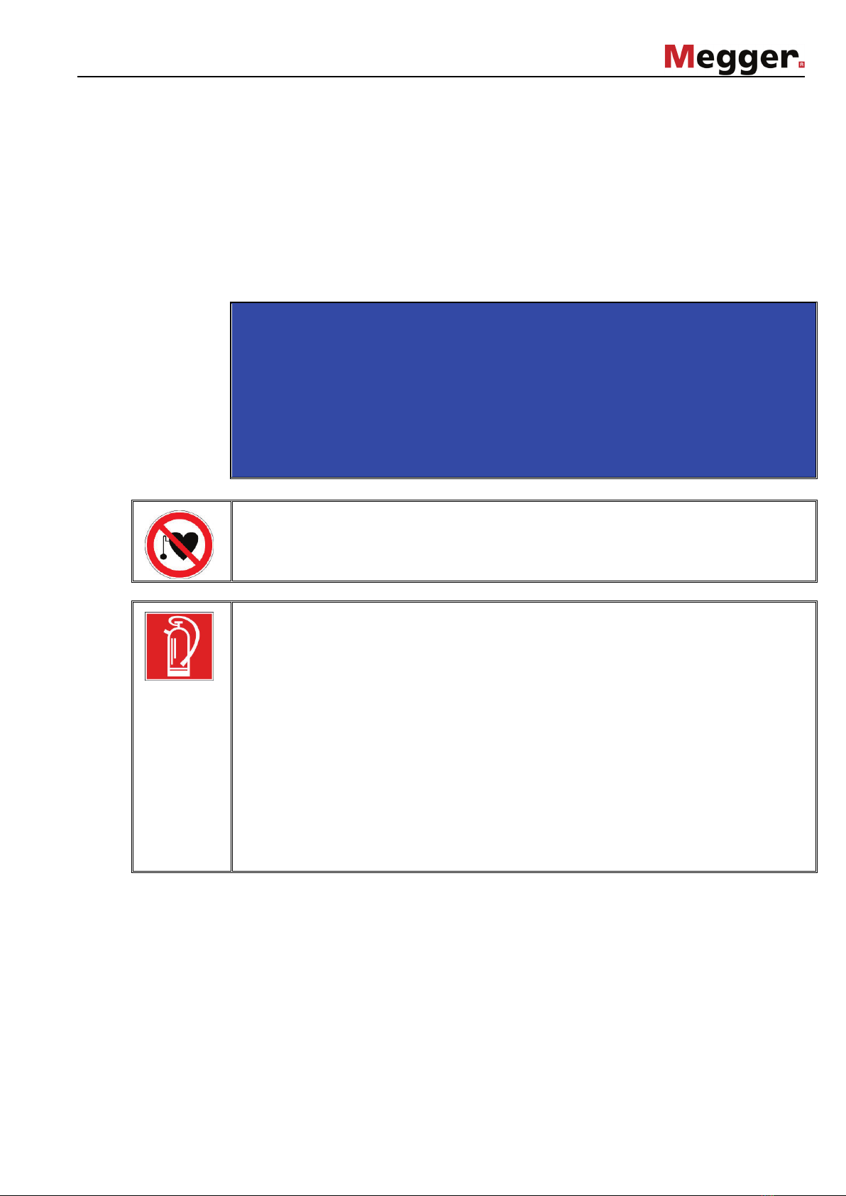
Using cardiac pacemaker
Physical processes during operation of high voltage may endanger persons wearing a
cardiac pacemaker when near these high voltage facilities.
Fire fighting in electrical installations
•According to regulations, carbon dioxide (CO2) is required to be used as
extinguishing agent for fighting fire in electrical installations.
•Carbon dioxide is electrically non conductive and does not leave residues. It is safe to
be used in energized facilities as long as the minimum distances are maintained. A
CO2fire extinguisher must be always available within electrical installations.
•If, contrary to the regulations, any other extinguishing agent is used for fire fighting,
this may lead to damage at the electrical installation. Megger disclaims any liability for
consequential damage. Furthermore, when using a powder extinguisher near high-
voltage installations, there is a danger that the operator of the fire extinguisher will get
an electrical shock from a voltage arc-over (due to the powder dust created).
•It is essential to observe the safety instruction on the extinguishing agent.
•Applicable is DIN VDE 0132.

8
WARNING
Dangers when operating with HV
Special attention and safety-
conscious behaviour is needed when operating HV
facilities and especially non-stationary equipment. The regulations VDE 0104 about
setting up and operation of electric test equipment, i.e. the corresponding EN 50191
as well as country-specific regulations and standards must be observed.
•The VLF Sinus 34 kV generates a dangerous voltage of up to ±24 kVRMS during
testing. This is supplied via a HV cable to the test object.
•The test system may not be operated without supervision.
•Operation requires minimum two people whereas the second person must be
able to activate the emergency switch in case of danger.
•Safety installations may not be by-passed nor deactivated.
•To avoid hazardous electric charges of metallic parts in the vicinity, all metallic
parts must be grounded.
•Check whether there are any unsecured live systems or components in the im-
mediate vicinity of the test system which might you or the system might
accidentally come into contact with. This particularly applies to components
which carry high voltage or where the voltage is unknown.
Secure these components using insulating covers. If technical reasons make it
impossible to do this, switch them off or have this action carried out at the site for
the duration of your work after consulting whoever is responsible. Make sure this
is done properly.

9
2 Technical Description
2.1 General Description
Functional description The VLF Sinus test system enables testing of medium-voltage cables in accordance with
the CENELEC Harmonization Documents HD 620 S1:1996 und HD 621 S1:1996 with a
0.1 Hz sine wave voltage of up to 24 kVRMS.
With the aid of such cable testing, faults in the insulation - particularly water tree damage -
will be reliably made to flash over in PE/XLPE cables but also in paper insulated cables.
The test procedure does not damage fault-free insulation.
The cables can also be tested for dielectric breakdown strength with positive and negative
DC voltage, as well as with trapezoidal AC voltage (rectangular wave voltage).
The slew rate of the rectangular wave voltage depends on the cable capacitance and is
automatically adapted.
The additional leakage current measurement
in DC mode enables evaluation of the
relative quality of the cable insulation.
The sine-wave shape of the system test voltage can also be used in combination with the
tan Delta test attachment from Megger to determine the loss factor and thus the cable's
degree of deterioration. A detailed description of this use can be found in the operating
manual of the tan Delta test attachment.
Features The VLF Sinus test system unites the following features and functions in a single device:
•Full AC voltage testing up to 24 kVRMS (sine wave voltage)
•Additional output voltage shapes of DC and rectangular wave
•Sheath testing and pinpointing up to 10 kV
•Leakage current measurement
•Manual and automatic frequency adjustment
•Voltage breakdown detection with automatic disconnection of the high voltage
•Logging to USB
•Firmware updates via USB
Scope of delivery The scope of delivery of the test system comprises the following components:
•Trolley bag with extendable handle
•Mains power cable, 2.5 m
•Earthing cable, 4 m
•HV connection cable, 5 m
•USB stick
•Operating manual
•Accessory bag

10
2.2 Technical Data
The VLF Sinus 34 kV test system is defined by the following technical parameters:
Parameter Value
Output voltage (sine wave)
Testing
Loss factor measurement with
the tan Delta test attachment
max. 24 kVRMS (33.9 kVPEAK)
max. 21,2 kVRMS (30 kVPEAK)
Source output current 8.8 mARMS (12.45 mAPEAK)
Leakage current measurement 0 … 14 mA
Frequency 0.01 Hz … 0.1 Hz
(automatic or settable in 0.01 Hz increments)
Testable cable capacitance
24 kVRMS at 0.01 Hz
24 kVRMS at 0.1 Hz
see also section 2.3
3.5 µF
0.58 µF
Output voltage (DC) ±33.9 kV
Output voltage (sheath testing
and sheath pinpointing)
-10 kV DC
Power supply 110 V … 230 V ±15%, 50 / 60 Hz
Power consumption max. 400 VA
Operating temperature -20 °C ... +55 °C
Storage temperature -25 °C ... +70 °C
Dimensions (W x H x D) 520 mm x 450 mm x 300 mm
Weight 25 kg
Display 3.5" colour display, 320 x 240 pixels
Interfaces USB, Ethernet
Protection class (in accordance
with DIN VDE 0140 Part 1)
I
Protection rating
(in accordance with EN 60529)
IP 54 (for enclosed housing)
IP 20 (open)

11
2.3 Testable Cable Capacities
Introduction The following
diagrams show the relation of the test frequency to the connected load
capacitance and the set test voltage.
If the set test frequency cannot be used due to the restrictions visible here, the system
prompts for a switch to the lowest possible frequency or, if automatic frequency adaption is
enabled, immediately switches to this frequency.
Sine-wave shaped
output voltage
Rectangular output
voltage

12
2.4 Connectors and Controls
The system has the following connectors and controls:
Element Description
USB slot
Emergency off button
Ethernet interface
for servicing and remote control
On/off button
HV “interlock” key switch
“HV ON” button
Display
Rotary encoder
Fuses F1 / F2 (2 x T4A)
Power supply socket
Protective earthing connection
HV output
“HV OFF” button
13
12
11
10
9
8
7
6
5
4
3
2
1
4
7
8
9
11
5
6
12
1
2
3
13
10

13
3 Setting Up the System
WARNING
Safety instructions for setting up
•
Select a location which is sufficient for the weight and size of the system and ensures
that it stands securely.
•When setting up the testing system, ensure
that it does not impair the function of any
other systems or components. If other systems and components have to be modified
in order to set up and operate the test system, be sure to reverse these actions when
th
e work is finished. Always take the special requirements of these systems and
components into account and only carry out work on them after consulting and
obtaining approval from whoever is in charge of them.
•Install protective equipment (such as railings,
chains or bars) near the test object to
block access to the danger zone and prevent the risk of touching live parts.
•The ventilation slits on the front and back sides of the front panel must not be covered.
•In the event of larger differences in temperatur
e between the storage and installation
locations (cold to warm) condensation may form on components carrying high voltage
(condensation effect). To avoid any risk of damage to people and components caused
by voltage arc-overs, the device needs to be acclimated for about half an hour while
being switched on (fans are running) before high voltage operation can be started.
3.1 Electrical Connection
WARNING
Safety instructions for the electrical connection
•Always follow the safety instructions in chapter 1 - in particular the five safety rules -
before connecting the test object.
•The test system may on
ly be connected to or disconnected from a test object when it
is switched off, and only when the test object is earthed and shorted.
•
Since the voltage applied to the test object can assume values that pose a risk of
incidental contact, the cable ends must
be shielded in accordance with VDE 0104 to
avoid this. When doing so, be sure to take all cable branches into account as well.
•
After granting clearance to the test object, make sure that dangerous voltage cannot
reach unprotected places or technical equipment.
•
The discharge switch installed in the device is merely an apparatus for safely
discharging capacitance, and not an earthing and shorting device as described by
VDE 0104.
•Before operating the system, any existing voltage transformers must be disconnected
from the test object.
•
All cables which are out of operation and not connected to the test system must be
shorted and earthed.

14
Connection diagram The following figure shows the simplified connection diagram:
Connection sequence
Connect the system in the following order:
Step Action
1 The earthing cable is to be fastened on the earthing connection of the
system and then connected to a suitable point on the protective earthing
system of the station.
2 Attach the high voltage connection cable to the HV output of the
system as shown in the figures below:
12
11
110 V … 230 V
50 / 60 Hz
Cable test in DC+, DC
-, VLF Sinus or VLF Rectangle mode
Sheath testing and pinpointing
110 V … 230 V
50 / 60 Hz

15
Step Action
3 The inner conductor of the HV connection cable must be connected by
means of suitable connection accessories to either the phase or the
screen of the cable under test.
When working in sheath test or sheath pinpointing mode, the cable
screen must not be connected to earth on both ends of the cable.
Make also sure that there is no indirect contact to earth, e.g. through
joints.
4 The screen of the HV connection cable has to be connected to an earth
bar close to the cable termination (system earth).
5 Plug the supplied power cable into the power connection of the system
and connect it to a mains socket.
3.2 Switching On the System
Switching on Before it is switched on with the on/off button , the device is in the 'Out of service' state.
Once the button is pressed, the system is in the 'Ready for operation' state. The
operational readiness is indicated by the lit button. The controls are activated and after a
short booting phase the start menu appears.
The high voltage source is switched off and the high voltage output is earthed via a
discharge resistor.
After the booting process, the start menu appears, from which a test with the settings of
the previous test can be immediately started via the Start button (see section 4.4).
If instead you need to change the system or test settings in preparation for the upcoming
test, the Menu button takes you to the settings menu (see section 4.3).
VLF Sinus 34 kV
10.10.2008 / 14:06:19
Mode:
VLF Sinus
30min
Menu Start
5.0kV
4
10

16
4 Stand-Alone Operation
4.1 Basics of Operation
Operation with rotary
encoder
Navigation within the menus is done using the rotary encoder as follows:
Turning = selecting
Pressing = confirming (“Enter” function)
The currently selected menu item can be identified by its background colour.
With the aid of the rotary encoder, the individual menus can be accessed and values can
be entered. Once a menu item with an adaptable parameter is selected, it is then shown
enlarged. The value for the parameter can then be adapted by turning the rotary encoder
and pressing it again to confirm.
Switching high
voltage on / off
Before the start of the test, the user is prompted to enable high voltage. To do so, the
green illuminated “HV ON” button must be pressed.
This lifts the resistor discharge and enables the generation of high voltage. The red
illuminated “HV OFF” button signals high voltage at the HV output. The green button
goes dark.
The switching on of high voltage requires the conditions of the safety circuit to be fulfilled,
which are described in section 4.2.
The high voltage can be switched off at any time during the course of the test via the
“HV OFF” button . The test is then immediately aborted and the system is placed in the
'Ready for operation' state. High voltage is switched off and the HV output is discharged.
Use of a USB stick To import firmware updates into the system or to record the log data of tests, a USB stick
must be inserted into the provided slot:
While the system detects the USB stick, the icon in the top left of the display is
flashing for appr. 5 seconds. After the icon stops flashing, the stick is ready for use.
13
13
6
20.0 kV
RMS
20.0 kV
RMS
10.0 kV
RMS
10.0 kV
RMS
selected
not
selected
8

17
4.2 Safety Measures
Introduction Once high voltage is enabled, the system's safety circuit continuously checks all safety-
relevant parameters and switching operations of the system. Should the safety circuit
detect a deviation from the monitored requirements while in high vol
tage mode, the
system automatically switches back to the 'Ready for operation' state. High voltage is
switched off and the HV output is discharged. The fault that occurred is shown in the
display and must be eliminated before test mode can be activated again.
Conditions of the
safety circuit
The following conditions must be fulfilled in order to perform tests under high voltage:
•The HV key switch must be in the position.
•The emergency off button must not be pressed.
•F-Ohm: The transfer resistance between protective earth and high voltage return may
not exceed 6 Ω(possible fault sources: poor earthing conditions or HV plugs that are
not securely bolted).
•The temperature within the system must be under a value which would jeopardise
operation.
Fault messages
The safety circuit checks the conditions in a hierarchical manner according to the
prescribed sequence and stops as soon as it detects a deviation. The following example
shows the system message after triggering of the F-Ohm monitor:
If a fault is directly resolved, its status changes to OK and the subsequent conditions are
checked.
The safety circuit can also be queried before the start of a test while the system is in the
'Ready for operation' state by means of a menu item provided for this purpose (see
page 18).
2
5
Safety circuit
Key switch OK
Emergency OFF switch OK
F-Ohm Error
Overtemperature ?
Back

18
4.3 Settings
After the booting process, the start menu appears, from which a test with the settings of
the previous test can be immediately started.
If you instead wish to change the operation mode, the test parameters
or the system
settings, selecting Menu will take you to the settings menu:
In the upper portion of the menu, similarly to nearly all other menus, general information
such as date / time and the currently selected test voltage shape is displayed.
From the settings menu the following functions can be accessed:
•Querying the status of the safety circuit (see section 4.2)
•Changing device settings (see section 4.3.1)
•Changing the operating mode and the test parameters (see section 4.3.2)
•Returning to start menu (see section 3.2)
VLF Sinus 34 kV
10.10.2008 / 14:06:19
Mode:
VLF Sinus
Safety
Circuit
Device
setup
Mode
Back
Test
setup

19
4.3.1 Device Settings
The Device setup menu can be accessed from the settings menu (see page 18).
Menu item Description
Date and
Time
This menu item is used to change the date and time shown in the upper
portion of the display.
Press the rotary encoder to jump from value to value and turn it to adapt
the individual values.
Systeminfo This menu item is used to obtain detailed system information such as
serial numbers and version numbers.
Language This menu item is used to change the language of the system.
Update This menu item is used to import firmware updates for various modules
of the system (e.g. application, boot loader, kernel). The required files
must be contained in the updates folder on the USB stick plugged in the
system.
After the system has automatically recognised all relevant files, the
updates are started. If the version of the firmware on the stick is older
than or identical to the currently installed version, the update must be
confirmed by the user.
Only update with firmware provided by Megger.
Do not switch off the system during the update. If you do, the system
will have to be repaired by Megger Service.
Service A password-protected service menu which can only be accessed by a
service technician.
Back This menu item is used to return to the settings menu (see page 18).
VLF Sinus 34 kV
Day: 10 Hour: 14
Month: 10 Minute: 42
Year: 2008 Second: 33
Back Update
Service
Date and
Time
Language
English
Systeminfo

20
4.3.2 Changing the Test Settings
Changing the
operation mode
To select the operation mode, select Mode from the settings menu (see page 18).
Menu item Description
VLF-Sinus In this mode, the test object is tested with a true VLF sine wave voltage
of up to 24 kVRMS (33.9 kVpeak) and a frequency of between 0.01 Hz and
0.1 Hz (settable).
DC+ In this mode, the test object is tested with positive DC voltage of up to
33.9 kV.
This mode is especially useful for testing the dielectric strength of a
newly laid or disconnected cable (particularly for paper insulated cables).
DC- In this mode, the test object is tested with negative DC voltage of up to
33.9 kV.
This mode is especially useful for testing the dielectric strength of a
newly laid or disconnected cable (particularly for paper insulated cables).
VLF-
Rectangle
In this mode, the test object is tested with a rectangular AC voltage with
an amplitude of up to 33.9 kV and a frequency of between 0.01 Hz and
0.1 Hz (settable).
The slew rate is automatically adapted.
This mode is especially suitable for start-up testing of the dielectric
strength of a newly laid or disconnected cable.
Sheath
Test
In this mode, the sheath of the test object (e.g. a newly laid cable
system) is tested with negative DC voltage of up to 10 kV.
Sheath
Pinpointing
In the case that the results of a sheath test do indicate the presence of a
sheath fault, the sheath pinpointing mode can be used to immediately
pinpoint the fault position by means of the step voltage method.
Thereby, the fault position is pinpointed with a pulsed DC voltage of up
to 10 kV and a duty cycle of either 1:3 or 1:4.
Back This menu item is used to return to the settings menu (see page 18).
Mode:
VLF-Sinus
Back
VLF-
Rectangle
VLF-Sinus
DC-
DC+
Sheath
Test
Sheath
Pinpointing
Table of contents
Other Megger Test Equipment manuals

Megger
Megger S1-552/2 User manual

Megger
Megger DET14C User manual

Megger
Megger SVERKER 900 User manual

Megger
Megger BM5200 Quick start guide

Megger
Megger MLR10 User manual

Megger
Megger T22/13B User manual

Megger
Megger SVERKER 900 User manual

Megger
Megger AVTMTTR100 User manual

Megger
Megger MFT1741 User manual

Megger
Megger DELTA 4000 User manual

Megger
Megger MFT1700 series User manual

Megger
Megger T 22/1 User manual

Megger
Megger DET3 Series User manual

Megger
Megger SMART THUMP ST16 User manual

Megger
Megger DET Series User manual

Megger
Megger S1-554/2 User manual

Megger
Megger MIT510/2 User manual

Megger
Megger BITE 2 User manual

Megger
Megger TRS1PLUS User manual

Megger
Megger DET5/4R User manual