SIGNALBOOSTER Industrial 100K User manual


H
BOOST
TABLE
OF
CONTENT
TABLE
OF
CONTENTS
OPERATION
PACKAGE
CONTENTS
KEY
FEATURES
KEY
COMPONENTS
HOW
TO
INSTALL
THE
SIGNAL
BOOSTER
1.1
Overview
1.2
Installation
Preparation
1.3
How
to
find
the
location
with
the
strongest
received
signa
1.4
Install
Outdoor
Antenna
1.5
Install
Indoor
Antenna
1.6
Install
the
signal
booster
1.7
Run
coaxial
cable
1.8
Power
up
your
signal
booster
1.9
Booster
Commissioning
SIGNAL
BOOSTER
STATUS
LCD
Status
LED
Status
Control
Buttons
Operation
and
Manual
gain
control
(
MGC
)
••
TROUBLESHOOTING
FCC
RF
EXPOSURE
STATEMENT
IC
RF
EXPOSURE
STATEMENT
WARNING
AND
STATEMENT
SPECIFICATIONS
PRODUCT
WARRANTY
2
3
3
5
5
6
6
6
8
10
10
11
11
12
13
14
16
17
19
20
21
21
22
23
ABBREVIATIONS
and
PHRASES
USED
IN
THIS
MANUAL
ALC
:
Automatic
Level
Control
DL
:
Downlink
(
Signal
transmitted
from
local
cell
site
tower
to
phone
)
UL
:
Uplink
(
Signal
transmitted
from
phone
to
cell
site
tower
)
MGC
:
Manual
Gain
Control
dBm
:
The
power
ratio
in
decibels
(
dB
)
of
the
measured
power
referenced
to
one
milliwatt
(
mW
)
.
'
Slow
Flashing
'
:
Less
than
one
flash
per
second
'
Fast
Flashing
'
:
More
than
one
flash
per
second
2
/
23

OPERATION
This
manual
covers
operation
,
installation
and
troubleshooting
procedures
for
the
bi
-
directional
amplifier
Model
:
Industrial
100
K
.
The
Industrial
100
K
amplifier
is
designed
to
help
wireless
device
users
amplify
weak
signals
of
all
the
major
carriers
in
the
2
G
,
3
G
and
4
G
bands
.
This
bi
-
directional
amplifier
is
used
to
boost
uplink
signals
from
the
phone
to
the
local
cell
site
tower
and
simultaneously
amplifying
downlink
signals
transmitted
from
the
tower
to
the
phone
.
An
antenna
located
outdoors
(
donor
antenna
)
receives
signals
from
the
cell
site
tower
,
transmits
them
to
the
amplifier
and
then
rebroadcasts
them
on
antennas
located
indoors
to
the
wireless
device
.
The
indoor
antennas
also
received
signals
transmitted
from
the
phone
that
are
boosted
in
the
amplifier
and
sent
to
the
tower
via
the
outdoor
donor
antenna
.
PACKAGE
CONTENTS
No
.
Name
Description
Quantity
Industrial
100
K
Amplifier
1
1
Power
Supply
12
V
/
7
A
2
1
Plastic
Expansion
Bolt
08
3
5
Tapping
Screw
M
6
*
50
4 4
User
Manual
5
1
ft
BOOST
l
12
V
/
7
A
AC
/
DC
Power
Supply
*
Outdoor
and
indoor
antennas
and
cables
are
required
for
installation
(
purchased
separately
)
.
Industrial
100
K
Booster
The
Industrial
100
K
industrial
amplifier
requires
outside
and
inside
antennas
connected
with
appropriate
coaxial
cables
and
a
splitter
network
.
The
Industrial
100
K
can
typically
power
8
-
15
indoor
antennas
but
the
exact
number
of
antennas
,
length
of
cable
or
other
accessories
needed
can
vary
according
to
the
size
and
construction
materials
used
in
the
building
,
outdoor
signal
strength
and
layout
of
the
structure
.
Please
contact
us
for
assistance
in
designing
your
system
.
3
/
23


Cavity
Splitter
(
2
,
3
,
4
way
)
Wilkinson
Splitter
(
2
,
3
,
4
way
)
KEY
FEATURES
•
Self
-
adaptive
Smart
Level
Control
(
ALC
)
:
Enables
convenient
'
plug
and
play
'
installation
and
optimum
coverage
in
complex
and
dynamically
changing
RF
signal
environments
.
•
ISO
:
Smart
isolation
gain
processing
to
avoid
self
-
oscillation
between
antennas
and
avoid
interference
to
the
carrier
network
.
•
LCD
Display
:
Displays
ISO
status
,
ALC
status
,
actual
gain
and
downlink
output
power
in
each
band
to
enable
easy
installation
and
troubleshooting
.
•
MGC
:
Manual
Gain
Control
adjustments
to
independently
change
gain
for
both
the
uplink
and
downlink
,
31
dB
range
.
•
Excellent
RF
Performance
:
27
dBm
downlink
power
available
to
overcome
loss
in
long
cable
runs
and
splitter
networks
.
•
Low
Profile
Enclosure
:
Light
weight
compact
wall
-
mount
with
low
power
consumption
and
heat
dissipation
.
KEY
COMPONENTS
The
following
drawing
shows
the
key
components
of
the
booster
.
1
.
LCD
Display
2
.
Control
Buttons
3
.
LED
Indicators
4
.
Outdoor
Antenna
Port
(
Type
N
-
Female
)
5
.
Indoor
Antenna
Port
(
Type
N
-
Female
)
6
.
Power
Connector
31
°
o
°
(
O
o
°
*
4
5
6
4
I
S
UlL
U
u
5
/
23

H
/
BOOST
HOW
TO
INSTALL
THE
SIGNAL
BOOSTER
1.1
Overview
This
manual
will
help
you
properly
install
your
signal
booster
.
It
is
important
to
read
through
all
of
the
installation
steps
before
installing
your
equipment
.
Thoroughly
read
through
the
instructions
,
visualize
where
all
the
equipment
will
need
to
be
installed
and
do
a
soft
installation
by
placing
the
devices
where
they
need
to
be
before
mounting
any
equipment
.
1.2
Installation
Preparation
Before
you
install
•
Make
sure
you
have
sufficient
cable
length
between
the
proposed
outdoor
/
indoor
antennas
and
the
amplifier
.
•
Make
sure
the
mounting
location
is
near
an
existing
electrical
outlet
,
well
ventilated
,
away
from
excessive
heat
,
moisture
,
and
direct
sunlight
.
Tools
Required
/
T
D
Phillips
Screwdriver
Drill
Mobile
Phone
No
.
Name
Specification
Quantity
Remark
Standard
accessories
1
Plastic
Expansion
Bolt
08
5
Tapping
Screws
M
6
*
50
Standard
accessories
2
4
Electric
Drill
3
1
Drill
Bit
4
1
Before
you
get
started
,
you
will
need
to
plan
the
layout
of
your
system
.
This
involves
finding
the
location
with
the
strongest
received
signal
from
the
cellular
tower
,
as
well
as
antenna
,
booster
,
and
cable
placement
.
General
installation
steps
:
1
.
Find
the
strongest
received
signal
for
the
location
of
the
outdoor
antenna
.
2
.
Install
the
outdoor
antenna
on
the
roof
to
obtain
the
strongest
downlink
signal
from
the
local
cellular
towers
.
It
should
also
be
as
far
away
as
possible
from
where
you
plan
to
place
the
indoor
antenna
(
vertical
separation
is
more
important
than
horizontal
separation
)
.
3
.
Install
the
indoor
antennas
where
you
want
to
improve
the
signal
level
.
6
/
23

4
.
Mount
the
booster
,
connect
the
cables
from
the
outdoor
antenna
and
indoor
antenna
at
the
designated
ports
,
and
connect
the
booster
to
the
AC
supply
(
make
sure
all
the
cables
are
connected
before
applying
power
)
.
1.3
How
to
find
the
location
with
the
strongest
received
signal
The
outdoor
signal
strength
the
booster
receives
directly
affects
the
efficiency
of
the
indoor
coverage
.
That
is
why
it
is
crucially
important
to
install
the
antenna
at
a
good
location
and
point
it
properly
towards
a
tower
where
signal
reception
is
the
strongest
.
There
are
many
methods
that
can
be
used
to
find
the
strongest
signal
from
the
cellular
towers
.
One
is
to
use
the
LCD
display
on
the
booster
that
shows
the
downlink
power
output
of
the
booster
in
each
band
,
the
other
is
to
use
a
mobile
phone
or
mobile
phone
app
to
test
signal
strength
,
and
the
third
is
to
use
a
commercially
available
signal
strength
meter
.
We
highly
recommend
that
you
use
the
LCD
display
on
the
booster
as
this
method
is
generally
more
convenient
.
However
,
in
situations
where
the
desired
carrier
'
s
signal
is
much
weaker
than
the
other
local
signals
,
using
a
mobile
phone
,
app
or
signal
level
meter
can
be
a
more
accurate
method
of
homing
in
on
the
best
signal
for
installation
.
•
LCD
Display
Method
Connect
the
outdoor
antenna
to
the
booster
'
s
outdoor
port
.
Fix
the
outdoor
antenna
on
the
roof
of
the
building
and
point
it
to
the
nearest
cell
tower
.
Then
have
a
look
at
the
gain
and
output
power
value
displayed
on
the
amplifier
'
s
LCD
.
Band
UL
DL
Power
dB dB
LTE
700
80
83
Cell
800
80
83
PCS
1900
80
83
27
AWS
2100
80
83
27
dfi
,
27
ISO
ALC
OFF
«
-
T
|
The
outdoor
antenna
receives
the
strongest
signal
when
the
booster
'
s
downlink
output
power
reaches
its
highest
level
in
each
band
.
If
the
LCD
shows
maximum
gain
and
power
,
and
there
are
not
any
alarms
(
no
ISO
,
ALC
,
OFF
legend
flashing
and
no
quick
flashing
green
or
red
in
LEDs
)
,
it
means
the
present
location
is
the
best
for
ensuring
that
the
booster
has
maximized
performance
.
The
maximum
downlink
power
for
Industrial
100
K
is
27
dBm
,
and
the
maximum
7
/
23

H
/
BOOST
downlink
gain
is
83
dB
.
Note
:
These
showed
values
may
vary
dynamically
at
times
between
1
-
3
dB
which
is
normal
due
to
outdoor
signal
conditions
.
When
the
ALC
legend
is
flashing
,
it
means
the
received
signal
power
is
stronger
than
the
system
needs
it
to
be
.
It
is
recommended
to
adjust
the
outdoor
antenna
orientation
until
the
ALC
alarm
disappears
.
Or
you
can
leave
it
as
it
is
to
let
the
booster
self
-
adjust
automatically
.
However
,
when
the
ALC
flashes
,
and
the
displayed
gain
is
30
dB
less
than
the
amplifier
'
s
rated
max
gain
value
,
try
to
adjust
the
outdoor
antenna
to
decrease
the
received
signal
power
from
the
local
tower
.
Otherwise
it
may
be
necessary
to
install
an
attenuator
on
the
outdoor
antenna
port
to
decrease
the
input
signal
level
from
the
local
tower
.
•
Mobile
Phone
Method
You
can
use
a
telephone
to
test
signal
strength
on
the
top
of
the
building
.
The
number
of
bars
on
the
network
indicator
will
define
approximate
strength
of
the
received
signal
.
Normally
the
roof
of
the
building
is
the
best
place
to
receive
the
strongest
signal
.
As
shown
on
the
drawing
below
,
you
need
to
test
the
signal
in
the
points
from
A
to
E
,
and
select
the
location
with
the
best
signal
strength
for
outdoor
installation
.
It
is
recommended
to
use
a
mobile
app
that
can
display
in
a
test
mode
the
signal
level
in
dBm
units
.
It
is
more
accurate
than
checking
the
signal
bars
.
For
more
details
refer
to
http
:
//
blog
.
hiboostusa
.
com
/
signal
-
strength
-
measure
-
instructions
/
.
Note
:
Please
try
to
receive
a
signal
from
cell
towers
that
are
not
overloaded
with
multiple
users
.
This
can
be
estimated
by
the
population
density
in
the
area
served
by
the
tower
.
For
example
,
it
is
recommended
to
avoid
cell
towers
near
supermarkets
,
shopping
malls
,
stadiums
or
any
other
public
places
visited
by
many
people
regularly
.
This
will
help
maintain
reliable
phone
call
connections
and
higher
speed
data
services
.
Mark
the
strongest
received
signal
as
the
installation
location
and
direction
for
the
outdoor
antenna
.
1.4
Install
Outdoor
Antenna
Install
the
outdoor
antenna
at
the
location
with
the
strongest
received
signal
.
In
most
cases
an
outdoor
wide
band
directional
or
panel
antenna
is
the
best
outdoor
antenna
choice
.
IMPORTANT
:
Testing
the
signal
3
times
in
the
desired
location
before
installing
8
/
23

the
outdoor
antenna
will
help
ensure
the
most
smooth
and
stable
phone
calls
and
data
transmission
.
1
to
2
inch
®
L
-
bracket
©
!
U
-
bolt
A
nut
&
washer
bracket
© ©
waterproof
tape
H
Outdoor
wide
band
directional
antenna
installation
for
reference
O
©
1
to
2
inch
diameter
pole
L
-
bracket
C
3
11
/
23
U
-
bolt
nut
bracket
nut
&
washer
©©
T
0
waterproof
tape
Outdoor
wide
band
panel
antenna
installation
for
reference
Note
:
Be
sure
the
cradle
is
at
the
desired
height
and
rotated
toward
the
strongest
cellular
signal
before
tightening
the
nuts
.
Do
not
over
tighten
.
Wrap
waterproof
tape
around
the
connectors
between
outdoor
antenna
and
feeder
line
to
avoid
moisture
ingress
.
9
/
23

H
/
BOOST
1.5
Install
Indoor
Antenna
Select
indoor
wide
band
panel
antenna
or
indoor
wide
band
dome
antenna
as
an
indoor
antenna
according
to
your
needs
to
provide
indoor
coverage
.
Select
a
place
on
a
wall
in
the
area
where
you
need
better
reception
.
Mount
the
indoor
antenna
with
the
included
screws
as
shown
in
the
figure
below
.
slide
into
mount
IX
hanging
folder
tapping
screw
plastic
expansion
bolt
Indoor
wide
band
panel
antenna
installation
for
reference
When
choosing
an
indoor
wide
band
dome
antenna
,
the
best
place
to
install
it
is
in
the
center
of
area
that
needs
signal
improvement
.
Install
the
dome
antenna
as
shown
on
the
figure
below
:
W
GD
V
i
—
ij
QD
[
L
QD
[
L
Indoor
wide
band
dome
antenna
installation
for
reference
1.6
Install
the
signal
booster
The
signal
booster
should
be
mounted
in
an
easily
accessible
area
so
it
'
s
easy
to
perform
general
maintenance
.
The
area
is
properly
ventilated
and
not
exposed
to
excessive
heat
,
moisture
and
/
or
direct
sunlight
.
The
optimal
area
would
be
on
a
wall
located
near
a
power
outlet
.
Please
use
a
surge
protector
rated
at
a
minimum
of
1000
Joules
between
the
booster
'
s
power
adaptor
and
the
AC
power
outlet
on
the
wall
.
Mount
the
booster
with
the
included
screws
as
shown
in
the
figure
below
.
10
/
23

plastic
expansion
bolt
tapping
screw
1.7
Run
coaxial
cable
Loosely
run
the
supplied
coaxial
cable
from
your
outdoor
antenna
to
your
booster
connector
marked
"
Outdoor
"
.
We
recommend
applying
waterproof
tape
to
fully
waterproof
the
connection
.
Connect
the
indoor
antenna
cables
from
your
indoor
antenna
to
the
booster
connector
marked
"
Indoor
"
.
Tighten
the
connection
by
hand
.
(
After
you
have
tested
the
system
you
can
permanently
secure
the
coaxial
cable
)
.
As
you
route
and
pull
cabling
,
follow
these
general
guidelines
:
•
Bend
cables
and
route
them
smoothly
,
and
protect
the
outer
skin
against
any
damage
.
•
Keep
horizontal
cables
straight
and
fasten
them
with
a
tie
every
three
to
five
feet
.
•
Bind
and
fasten
vertical
cables
every
six
to
eight
feet
.
•
Waterproof
all
connectors
between
outdoor
antenna
and
coaxial
cables
with
waterproof
tape
to
avoid
water
or
other
kinds
of
damage
.
•
Be
careful
when
plugging
the
connector
in
so
as
not
to
damage
the
center
pins
on
the
connectors
.
1.8
Power
up
your
signal
booster
Once
all
the
following
precautions
have
been
taken
,
power
on
the
signal
booster
.
1
.
Verify
that
you
have
left
enough
vertical
separation
space
between
the
indoor
and
outdoor
antennas
.
2
.
Never
point
the
front
of
outdoor
antenna
towards
the
inside
of
the
indoor
antenna
.
3
.
Verify
that
the
supplied
coaxial
cables
from
both
the
outdoor
antenna
and
the
indoor
antenna
are
properly
connected
to
the
signal
booster
before
powering
it
up
.
4
.
Carefully
plug
in
the
supplied
power
adaptor
into
the
signal
booster
where
it
11
/
23
H
/
BOOST
is
marked
'
DC
12
V
1
and
connect
the
other
end
to
a
power
outlet
.
The
LED
indicator
marked
power
should
light
up
green
.
1.9
Booster
Commissioning
Overview
:
The
booster
has
a
smart
startup
system
.
When
you
have
finished
the
booster
system
installation
and
power
on
the
booster
,
it
will
start
its
initialization
process
to
check
the
received
downlink
signal
from
the
cell
site
and
the
isolation
status
.
This
an
automatic
process
designed
to
ensure
its
best
performance
.
This
will
take
approximately
3
-
5
seconds
.
After
the
booster
starts
up
,
please
check
if
the
coverage
is
good
.
If
it
is
good
,
the
booster
system
installation
is
complete
.
If
the
coverage
is
not
adequate
,
please
fully
reread
and
understand
the
LCD
,
LED
indications
,
control
buttons
and
MGC
function
on
your
booster
,
as
they
will
help
you
identify
and
solve
any
potential
issues
.
Check
the
downlink
output
power
displayed
by
the
LCD
.
It
may
vary
dynamically
at
times
between
1
-
3
dB
which
is
normal
due
to
outdoor
signal
conditions
.
It
would
be
optimum
that
the
output
power
reaches
its
maximum
rated
levels
for
the
largest
coverage
;
but
you
can
always
leave
it
set
at
lower
levels
if
the
coverage
is
adequate
.
Please
bear
in
mind
that
it
is
nearly
impossible
to
achieve
4
-
5
bars
on
every
phone
at
all
locations
in
a
building
.
Cellular
phones
will
operate
just
fine
if
they
are
showing
1
-
2
bars
.
Some
phones
by
different
manufactures
will
often
show
widely
different
signal
level
results
.
Also
,
phones
by
the
same
manufacture
can
show
different
results
if
they
have
different
software
versions
.
Because
of
very
large
indoor
RF
signal
multipath
effects
moving
a
phone
only
a
few
feet
can
result
in
large
changes
in
its
received
signal
level
.
If
the
coverage
is
not
adequate
,
please
take
the
steps
below
as
is
appropriate
for
each
situation
:
1
.
The
rated
output
power
is
reached
,
but
the
coverage
is
not
enough
or
the
signal
in
specific
areas
has
not
been
improved
.
•
Check
whether
the
indoor
antenna
is
installed
correctly
.
You
may
try
to
move
the
antenna
location
to
improve
coverage
.
•
If
an
indoor
panel
is
used
,
check
if
adjusting
the
pointing
direction
of
the
indoor
antenna
makes
any
difference
.
•
Check
whether
it
is
necessary
to
add
more
indoor
antennas
since
barriers
such
as
walls
will
block
the
signal
penetration
.
2
.
The
rated
downlink
output
power
is
not
reached
.
1
)
Please
adjust
the
outdoor
antenna
to
get
a
stronger
received
signal
from
the
tower
to
get
higher
downlink
output
power
(
not
necessarily
to
reach
rated
value
if
the
coverage
is
adequate
)
.
The
max
rated
downlink
power
for
this
amplifier
is
27
dBm
.
^
2
)
Please
observe
the
LCD
display
.
If
the
displayed
gain
is
much
less
than
the
i
12
/
23

rated
value
and
"
ISO
"
is
flashing
,
it
means
the
gain
is
being
reduced
by
the
ISO
function
because
there
is
not
enough
isolation
between
an
indoor
antenna
and
the
outdoor
antenna
.
SIGNAL
BOOSTER
STATUS
Working
Frequency
Uplink
Downlink
Gain Gain
Downlink
Output
Power
Relative
signal
power
from
tower
status
Indicator
f
,
Alarm
,
rJ
o
Band
UL
DL
dB
dB
LTE
700
80
83
Cell
800
80
83
PCS
1900
80
83
AWS
2100
80
83
Power
f
/
27
Powe
Indicates
DC
power
status
O
7
7
ISO
ISO
ALC
OFF
o
Antenna
Isolation
Status
Indicator
—
G
u
Band
Shut
Off
Indicator
Automatic
Level
Control
(
ALC
)
Activity
Indicator
(
O O
3
)
s
DEC
-
SET
INC
+
Band
:
Shows
the
working
frequency
bands
where
the
booster
is
operating
.
UL
/
DL
:
Shows
real
-
time
uplink
and
downlink
gain
(
dB
)
.
These
values
will
change
slightly
as
the
ALC
or
ISO
makes
changes
to
the
gain
to
optimize
coverage
.
Power
:
Shows
real
-
time
downlink
power
(
dBm
)
that
the
booster
is
delivering
to
the
indoor
antenna
port
.
When
the
booster
DL
output
power
is
lower
than
-
10
dBm
,
the
value
will
display
ISO
:
When
the
system
does
not
have
enough
isolation
between
the
outdoor
and
indoor
antennas
,
the
"
ISO
"
indicator
will
be
flashing
showing
that
the
ISO
has
lowered
the
gain
in
some
bands
to
keep
the
system
from
oscillating
.
Press
the
"
SET
"
key
and
the
LCD
screen
will
turn
on
to
help
with
troubleshooting
and
display
"
ISO
"
value
showing
the
current
band
or
bands
affected
.
ALC
:
When
the
booster
is
receiving
too
much
DL
power
from
the
tower
and
the
DL
booster
output
is
close
to
saturating
,
the
"
ALC
"
indicators
will
flash
showing
that
the
ALC
has
lowered
the
gain
to
prevent
this
overload
condition
.
Press
the
"
SET
"
button
and
the
screen
will
turn
on
to
help
with
troubleshooting
and
show
the
band
or
bands
affected
.
13
/
23
H
/
BOOST
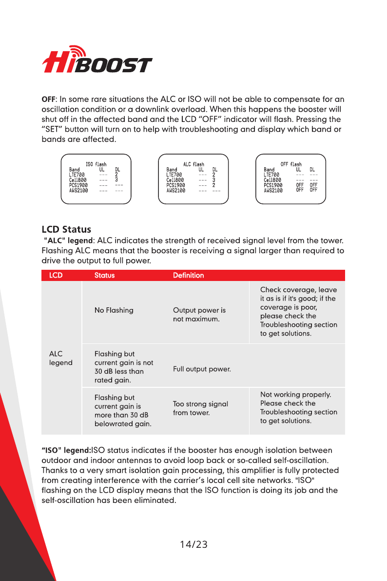
OFF
:
In
some
rare
situations
the
ALC
or
ISO
will
not
be
able
to
compensate
for
an
oscillation
condition
or
a
downlink
overload
.
When
this
happens
the
booster
will
shut
off
in
the
affected
band
and
the
LCD
"
OFF
"
indicator
will
flash
.
Pressing
the
"
SET
"
button
will
turn
on
to
help
with
troubleshooting
and
display
which
band
or
bands
are
affected
.
ISO
flash
ALC
flash
OFF
flash
Band
UL
DL
Band
UL
DL
Band
UL
DL
2
LTE
700
Cell
800
PCS
1900
AWS
2100
LTE
700
Cell
800
PCS
1900
AWS
2100
2
LTE
700
Cell
800
PCS
1900
AWS
2100
3
3
OFF
OFF
OFF
OFF
2
LCD
Status
"
ALC
"
legend
:
ALC
indicates
the
strength
of
received
signal
level
from
the
tower
.
Flashing
ALC
means
that
the
booster
is
receiving
a
signal
larger
than
required
to
drive
the
output
to
full
power
.
LCD
Status
Definition
Check
coverage
,
leave
it
as
is
if
it
'
s
good
;
if
the
coverage
is
poor
,
please
check
the
Troubleshooting
section
to
get
solutions
.
No
Flashing
Output
power
is
not
maximum
.
ALC
Flashing
but
current
gain
is
not
30
dB
less
than
rated
gain
.
legend
Full
output
power
.
Not
working
properly
.
Please
check
the
Troubleshooting
section
to
get
solutions
.
Flashing
but
current
gain
is
more
than
30
dB
belowrated
gain
.
Too
strong
signal
from
tower
.
"
ISO
"
legend
:
ISO
status
indicates
if
the
booster
has
enough
isolation
between
outdoor
and
indoor
antennas
to
avoid
loop
back
or
so
-
called
self
-
oscillation
.
Thanks
to
a
very
smart
isolation
gain
processing
,
this
amplifier
is
fully
protected
from
creating
interference
with
the
carrier
'
s
local
cell
site
networks
.
"
ISO
"
flashing
on
the
LCD
display
means
that
the
ISO
function
is
doing
its
job
and
the
self
-
oscillation
has
been
eliminated
.
14
/
23

LCD
Status
Definition
No
loopback
or
no
self
-
oscillation
.
No
Flashing
Working
properly
.
Flashing
but
current
gain
is
not
30
dB
less
than
rated
gain
.
Slight
loop
back
or
self
-
oscillation
.
ISO
legend
Flashing
but
current
gain
is
more
than
30
dB
below
rated
gain
.
Not
working
properly
.
Please
check
the
Troubleshooting
section
to
get
solutions
.
Deep
loop
back
or
self
-
oscillation
.
More
about
LCD
status
:
LCD
Status
Definition
Check
coverage
,
leave
it
as
is
if
it
'
s
good
;
if
the
coverage
is
poor
,
please
check
the
Troubleshooting
section
to
get
solutions
.
Output
power
is
lower
than
-
1
OdBm
.
Downlink
power
"
status
OFF
The
booster
automatically
shuts
off
for
protection
from
excessive
downlink
signal
from
tower
or
due
to
very
severe
self
-
oscillation
.
Flashing
Not
working
properly
.
Please
check
the
Troubleshooting
section
to
get
solutions
.
legend
Flashing
LCD
screen
Note
:
The
flashing
ISO
and
ALC
status
displays
indicate
that
ISO
and
ALC
functions
are
working
properly
,
and
the
problems
of
self
-
oscillation
and
strong
signal
are
corrected
.
In
most
cases
,
there
is
no
need
to
take
any
additional
measures
,
except
for
deep
self
-
oscillation
or
too
strong
downlink
signals
that
are
overloading
the
amplifier
.
However
,
in
most
cases
additional
measures
are
not
mandatory
,
since
the
self
-
adaptive
ALC
system
and
isolation
gain
processing
automatically
solve
most
problems
.
15
/
23

LED
Status
LED
Status
Definition
Green
Normal
Power
LED
Off
DC
power
problem
When
the
ISO
or
ALC
indicators
are
flashing
,
please
check
the
ISO
and
Alarm
LED
colors
.
•
ISO
LED
flashing
means
that
ISO
function
is
working
well
and
self
-
oscillation
has
been
eliminated
.
ISO
LED
will
remain
"
Green
"
or
will
be
"
Slow
Flashing
Green
"
.
Note
:
This
improvement
won
'
t
increase
the
coverage
,
but
is
mandatory
to
avoid
causing
interference
to
carrier
'
s
local
cell
site
towers
.
LED
Status
Definition
No
loopback
or
no
self
-
oscillation
.
Slight
loop
back
or
self
-
oscillation
.
Working
properly
.
Green
Slow
Flashing
Green
Not
working
properly
.
Check
coverage
,
leave
it
as
is
if
it
’
s
good
.
Please
check
the
Troubleshooting
section
to
get
solutions
if
coverage
is
not
good
.
ISO
LED
Quick
Flashing
Green
Deep
loop
back
or
self
-
oscillation
.
Not
working
properly
.
Please
check
the
Troubleshooting
section
to
get
solutions
.
The
booster
automatically
shuts
off
for
protection
due
to
very
severe
self
-
oscillation
.
Quick
Flashing
Red
Alarm
LED
:
Indicates
the
strength
of
received
signal
from
the
tower
.
Flashing
Alarm
means
that
the
booster
is
receiving
a
strong
signal
in
one
or
more
of
the
bands
.
Alarm
LED
shall
remain
"
Green
"
or
"
Slow
Flashing
Green
"
.
Slow
flashing
green
indicates
that
everything
is
working
well
and
the
booster
is
working
at
nearly
the
optimum
output
power
to
achieve
the
best
possible
coverage
16
/
23

Status
LED
Definition
Check
coverage
,
leave
as
is
if
it
'
s
good
;
if
the
coverage
is
poor
,
please
check
the
Troubleshooting
section
to
get
solutions
.
Green
Output
power
is
not
maximum
.
Working
properly
.
Slow
Flashing
Green
Full
output
power
.
Alarm
LED
Quick
Flashing
Green
Output
power
is
too
high
.
Not
working
properly
.
Please
check
the
Troubleshooting
section
to
get
solutions
.
The
booster
automatically
shuts
off
for
protection
from
excessive
downlink
signal
from
tower
.
Quick
Flashing
Red
Note
:
The
slow
flashing
ISO
and
Alarm
status
indicates
that
ISO
and
ALC
functions
are
working
properly
and
the
problems
of
self
-
oscillation
and
strong
downlink
signals
are
fixed
.
In
most
cases
,
there
is
no
need
to
take
any
additional
measures
except
for
deep
self
-
oscillation
or
excessively
strong
signals
from
the
tower
.
The
se
lf
-
adaptive
ALC
and
isolation
gain
processing
system
automatically
solve
most
p
'
oblems
.
Control
Buttons
Operation
and
Manual
gain
control
(
MGC
)
There
are
5
operation
modes
relative
to
the
control
keys
:
•
Press
the
"
SiET
"
key
for
more
than
3
seconds
•
Short
press
on
the
"
SET
"
key
•
Short
press
on
the
"
DEC
-
"
key
•
Short
press
on
"
INC
+
"
key
•
Simultaneously
press
on
the
"
DEC
-
"
and
"
INC
+
"
keys
for
more
than
3
seconds
Since
the
booster
has
a
self
-
adaptive
smart
automatic
level
control
(
ALC
)
and
isolation
gain
processing
(
ISO
)
,
most
of
the
time
manual
adjustments
are
not
required
to
cchieve
good
coverage
.
However
,
in
some
cases
where
the
ALC
or
ISO
is
workirg
at
a
very
high
rate
to
adjust
the
gain
and
the
Alarm
or
ISO
LED
is
flashing
more
than
once
a
second
,
a
manual
adjustment
might
be
desired
.
When
the
LCD
is
in
the
fixed
display
mode
,
press
the
"
SET
"
key
for
more
than
3
seconds
.
It
will
go
into
the
"
Gain
Setting
Mode
"
and
make
one
of
the
gain
values
start
to
blink
.
17
/
23

H
/
BOOST
•
Briefly
press
"
SET
"
key
,
and
the
LCD
will
switch
to
the
next
gain
value
and
it
will
start
to
blink
.
(
Uplink
or
downlink
gain
for
a
different
band
)
.
•
Press
"
INC
+
"
key
once
shortly
and
the
gain
will
increase
by
1
dB
,
Press
"
DEC
-
"
once
shortly
and
the
gain
value
will
be
reduced
by
1
dB
.
•
Press
the
"
SET
"
key
for
more
than
3
seconds
,
and
the
LCD
will
return
to
the
fixed
display
mode
.
Actual
Gain
display
MGC
Setting
Gain
Gain
Set
Band
UL
DL
UL
DL
PUR
dB dB
dB
dB
dBm
700
80
83
80
81
25
800
80
83
80
82
26
1900
80
83
80
83
27
2100
80
83
80
83
27
Actual
Power
display
Note
:
When
adjusting
the
gain
manually
,
please
ensure
that
the
uplink
gain
is
equal
to
or
not
5
dB
less
than
the
downlink
gain
setting
.
This
avoids
interference
with
the
local
cell
site
tower
network
.
When
the
LCD
is
in
the
fixed
display
mode
,
press
the
"
DEC
-
"
and
"
INC
+
"
key
simultaneously
for
more
than
3
seconds
,
the
booster
will
reset
the
gain
to
the
default
manufacturer
settings
.
When
the
LCD
is
in
the
alarm
display
mode
,
press
the
"
SET
"
key
and
the
LCD
screen
will
turn
on
to
help
with
troubleshooting
and
display
the
alarm
indication
showing
the
affected
band
or
bands
,
press
the
"
INC
+
"
(
or
"
DEC
-
"
)
key
will
switch
to
different
pages
.
If
none
of
the
keys
are
pushed
within
30
seconds
,
the
display
will
return
to
the
fixed
display
mode
.
If
none
of
the
control
keys
are
pushed
within
5
minutes
,
the
LCD
screen
will
turn
off
.
Pressing
any
key
will
return
the
display
to
the
fixed
mode
.
18
/
23

TROUBLESHOOTING
Solution
Problem
The
signal
booster
has
no
power
.
Check
that
the
AC
outlet
is
working
.
Check
all
the
connections
between
the
different
components
of
the
system
.
Change
the
direction
of
the
outdoor
donor
antenna
or
its
installed
position
.
Use
barriers
(
like
buildings
)
to
block
signals
of
other
operators
.
The
booster
'
s
power
is
on
but
the
phone
is
not
connected
to
the
network
and
still
cannot
communicate
with
the
tower
.
Check
whether
there
'
s
interference
.
Consult
the
operator
whether
the
signal
source
base
station
is
working
OK
.
Good
downlink
signal
but
with
poor
voice
or
link
quality
.
The
power
is
on
but
the
coverage
is
not
good
.
First
check
LCD
or
LED
status
.
Take
the
actions
mentioned
below
.
Eliminate
Flashing
ISO
legend
,
OFF
legend
and
Quick
Flashing
Green
,
Quick
Flashing
Red
ISO
LED
problems
:
1
.
Adjust
the
outdoor
antenna
direction
,
keeping
it
away
from
indoor
antenna
.
Restart
booster
.
2
.
Increase
the
vertical
or
horizontal
distance
between
the
outdoor
antenna
and
indoor
antenna
.
Restart
booster
.
3
.
Use
barriers
such
as
walls
to
increase
the
isolation
.
4
.
Change
the
indoor
antenna
type
to
an
antenna
with
a
more
directional
antenna
pattern
.
Orient
the
indoor
antenna
and
outdoor
antenna
so
they
point
in
opposite
directions
.
5
.
Reduce
the
booster
'
s
downlink
gain
using
the
manual
gain
controls
.
Keep
the
uplink
gain
value
and
downlink
gain
value
the
same
then
restart
the
booster
.
If
the
indoor
antennas
are
connected
through
a
splitter
network
locate
the
antenna
that
is
causing
the
ISO
alarm
by
disconnecting
each
indoor
antenna
one
at
a
time
and
insert
an
inline
attenuator
to
reduce
the
signal
power
going
to
that
particular
antenna
.
Note
:
Uplink
gain
must
be
equal
to
or
not
less
than
5
dB
below
the
downlink
gain
,
to
avoid
interference
with
the
local
carrier
'
s
cell
site
network
.
Target
:
The
ISO
issues
are
solved
when
the
ISO
LED
is
"
Green
"
or
"
Slow
Flashing
Green
"
or
no
flashing
ISO
legend
.
Eliminate
Flashing
ALC
legend
and
Quick
Flashing
Green
,
Quick
Flashing
Red
Alarm
LED
problems
:
19
/
23

H
/
BOOST
1
.
Adjust
the
antennas
'
directions
or
locations
to
lower
downlink
received
signal
level
.
2
.
Slowly
reduce
the
downlink
gain
using
the
Manual
Gain
Controls
.
3
.
If
the
above
methods
don
'
t
work
,
reduce
the
booster
'
s
gain
with
an
external
attenuator
in
line
with
the
outdoor
antenna
or
replace
with
lower
gain
antenna
.
Target
:
The
overload
issues
are
fixed
when
the
Alarm
LED
is
"
Green
"
or
"
Slow
Flashing
Green
"
or
no
flashing
ALC
legend
.
Please
note
that
a
"
Green
"
LED
indication
may
result
in
smaller
coverage
area
.
This
can
be
improved
by
adjusting
the
outdoor
antenna
to
receive
a
stronger
signal
.
Eliminate
poor
coverage
problems
when
Power
"
—
"
legend
or
no
flashing
ALC
Legend
on
LCD
and
Alarm
LED
is
Green
:
1
.
If
the
signal
in
most
areas
has
not
been
improved
,
please
check
below
:
•
The
weak
downlink
signal
leads
to
the
low
output
signal
level
.
Change
the
direction
or
position
of
the
outdoor
antenna
.
You
may
also
try
replacing
the
outdoor
antenna
with
a
higher
gain
antenna
to
increase
the
incoming
signal
.
•
Check
to
see
if
it
is
necessary
to
add
more
indoor
antennas
.
Barriers
such
as
walls
can
block
the
signal
indoors
.
You
should
also
check
the
booster
to
make
sure
the
power
is
maximized
.
Try
installing
more
indoor
antennas
or
replace
the
booster
with
a
higher
powered
one
.
2
.
If
the
signal
in
a
small
section
of
the
building
hasn
'
t
been
improved
,
try
the
following
:
•
Check
to
see
if
the
indoor
antenna
is
installed
correctly
.
Try
moving
the
antenna
to
improve
coverage
.
•
Try
adjusting
the
direction
the
indoor
antenna
is
pointing
.
•
Check
whether
it
is
necessary
to
add
one
or
more
antennas
to
enhance
the
coverage
of
special
areas
.
Remark
:
•
When
increasing
the
downlink
gain
make
sure
the
isolation
is
adequate
to
prevent
system
oscillation
.
•
Recommended
ways
to
increase
output
power
:
Adjust
the
outdoor
antenna
direction
/
location
,
or
replace
with
higher
gain
antenna
to
increase
received
signal
strength
from
the
tower
.
FCC
RF
EXPOSURE
STATEMENT
This
equipment
complies
with
FCC
radiation
exposure
limits
set
forth
for
an
uncontrolled
environment
.
This
equipment
should
be
installed
and
operated
with
minimum
distance
30
cm
between
the
radiator
&
your
body
.
This
transmitter
must
not
be
co
-
located
or
operating
in
conjunction
with
any
other
antenna
or
transmitter
.
20
/
23
Table of contents
Other SIGNALBOOSTER Extender manuals

SIGNALBOOSTER
SIGNALBOOSTER Fusion2Go 3.0 Fleet User manual

SIGNALBOOSTER
SIGNALBOOSTER Flare 3.0 User manual

SIGNALBOOSTER
SIGNALBOOSTER 470410 User manual

SIGNALBOOSTER
SIGNALBOOSTER MOBILE REPEATER KIT User manual

SIGNALBOOSTER
SIGNALBOOSTER CEL-FI QUATRA 4000 User manual

SIGNALBOOSTER
SIGNALBOOSTER Pro 1000 User manual


