SignalFire Sentinel-FS-3BIS User manual
1
SignalFire Telemetry
Rev 1.2
Interface Manual
Sentinel Float Scout
SignalFire Model: Sentinel-FS-3BIS
The SignalFire Sentinel Float Stick Node is an Intrinsically Safe device with the
following features:
-Standard SignalFire Sentinel RS485-Modbus Node
-RS485 connection to internal Float Stick Interface Board
-1 or 2 floats with temperature(s) supported
-Low power operation from an intrinsically safe high capacity lithium primary
battery pack
-Optional solar battery system for routing nodes or rapid data collection
-Sends data to a SignalFire Buffered Modbus Gateway
-AES 128bit encryption

2
SignalFire Telemetry
Rev 1.2
Specifications
Enclosure Size
3.5” tall ×5.0” wide ×5.0” deep
Power Source
Internal IS Lithium battery pack
SignalFire Part Number: 3BIS
External Solar battery system
SignalFire Part Number: Sentinel-HCSolar
DC-DC Converter
SignalFire Part Number: DCDC-Sentinel
Other external power supply meeting the power entity parameters from the
control drawing.
Temperature Rating
-40°C to +60°C
Radio Frequency
902-928MHz Ism Band, FHSS radio, internal antenna
Compliance
Measurement Resolution
Certified for use in Class I, Division 1 groups C and D. EXi [EXi] FCC/IC
(Certification Pending).
0.0001”
WARNING: Use of this equipment in a manner not specified by the manufacturer may
impair the protection provided by the equipment.
WARNING: The use of any parts not supplied by the manufacturer violates the safety rating
of the equipment.
The associated apparatus provides intrinsically safe outputs.
L’appareil associé fournit des sorties à sécurité intrinsèque.
Refer to control drawing “Sentinel –Control Drawing –Modbus, Thermocouple, RTD, and Float Stick for
requirements when used in a Class I Division 1 area.
3
SignalFire Telemetry
Rev 1.2
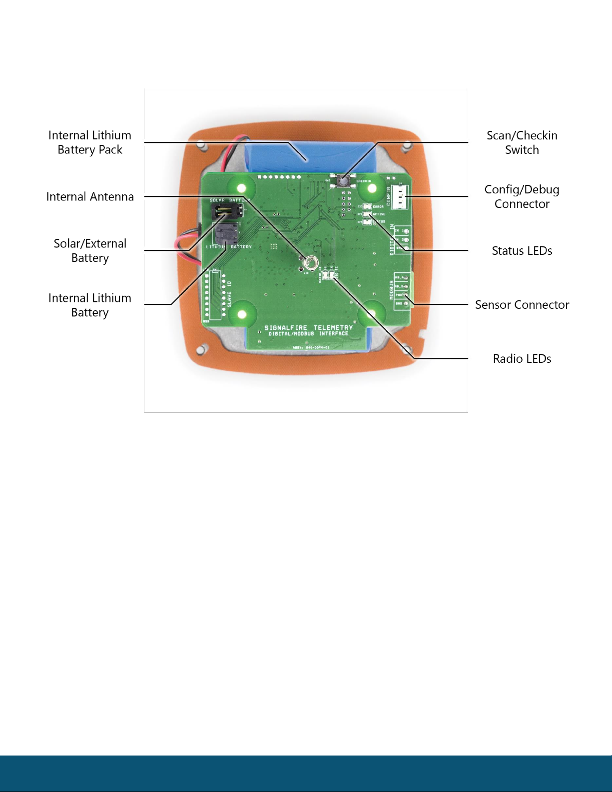
Connections and Components
Radio LEDs
-The Radio TX LED (green) flashes each time a radio packet is sent. This LED will blink rapidly while
searching for the radio network.
-The Radio RX LED (red) blinks on each received radio packet.
Status LEDs
-The Active LED (green) will blink at boot up and will blink rapidly when the sensor is being powered and
read.
-The ERROR LED (red) will blink to indicate an error condition.
Scan/Checkin Button
-If this button is pressed the Sentinel will take a reading from the Float Stick and send those values to
the gateway.

4
SignalFire Telemetry
Rev 1.2
Setup
The nodes need to be set up for correct operation before being fielded. The configurable items include:
-Network selection/Encryption settings
-Check-in period selection
-Float Stick mode enable
All settings are made using the SignalFire Toolkit PC application and a serial programming cable.
Using the SignalFire Toolkit
The SignalFire Toolkit application can be downloaded at www.signal-fire.com/customer. After installation,
launch the software and the main toolkit window will open:
Select the COM port associated with the Sentinel Node and click “Auto-Detect Device on COM Port.” This will
open the device configuration window, where all device settings can be configured.
WARNING: Perform the steps in this section (Setup) in a safe location only.
5
SignalFire Telemetry
Rev 1.2
Network Setting
The network is set using the SignalFire Toolkit. The network, network group, and corporate ID/encryption key
settings must match those of the gateway for them to communicate.
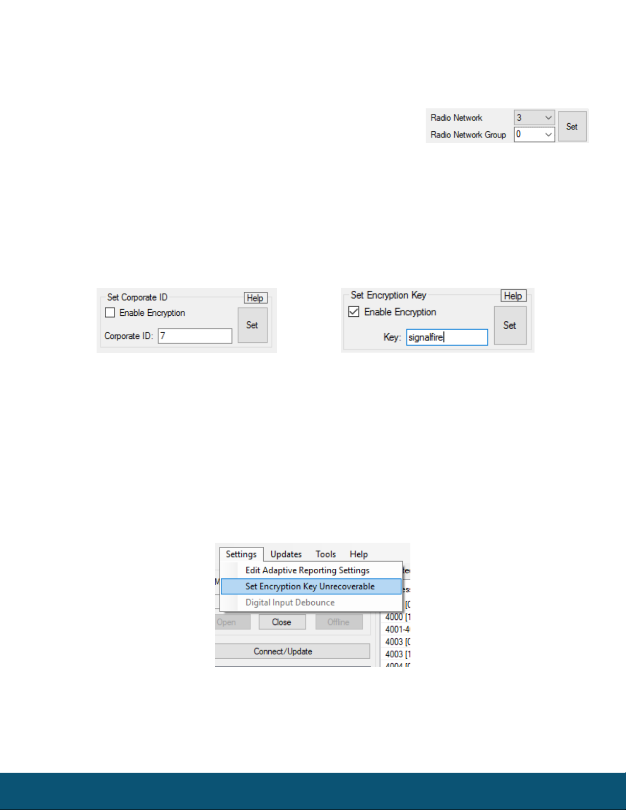
Encryption
To protect your over-the-air data and prevent tampering, SignalFire networks come with encryption. Legacy
products use a Corporate ID, but can be switched over to use an encryption key if the firmware and ToolKit are
up to date.
To set up a legacy Sentinel to use encryption, click the checkbox labeled Enable Encryption inside the Set
Corporate ID box. All newer Sentinels come with this option enabled with “signalfire” as the default encryption
key.
The box will then change into a Set Encryption Key box, and it will prompt instead for the encryption key you
would like to use. Note that keys may not contain spaces or angle brackets. Enter it and then press Set. If you are
setting up a new network, you will need to set the encryption key on all of your devices. If you are adding a
Sentinel to a legacy network, you can simply set the Corporate ID without clicking the Enable Encryption box,
and it will remain compatible with the older system.
It is also possible to hide your encryption key so it cannot be read. This is the most secure option, but if you
forget your key, there is no way to recover it – you have to reset the key on every device on its network. To enable
this option, select Set Encryption Key Unrecoverable under the Settings menu.
Setting the encryption key to be unrecoverable.
Encryption Enabled
Corporate ID
6
SignalFire Telemetry
Rev 1.2
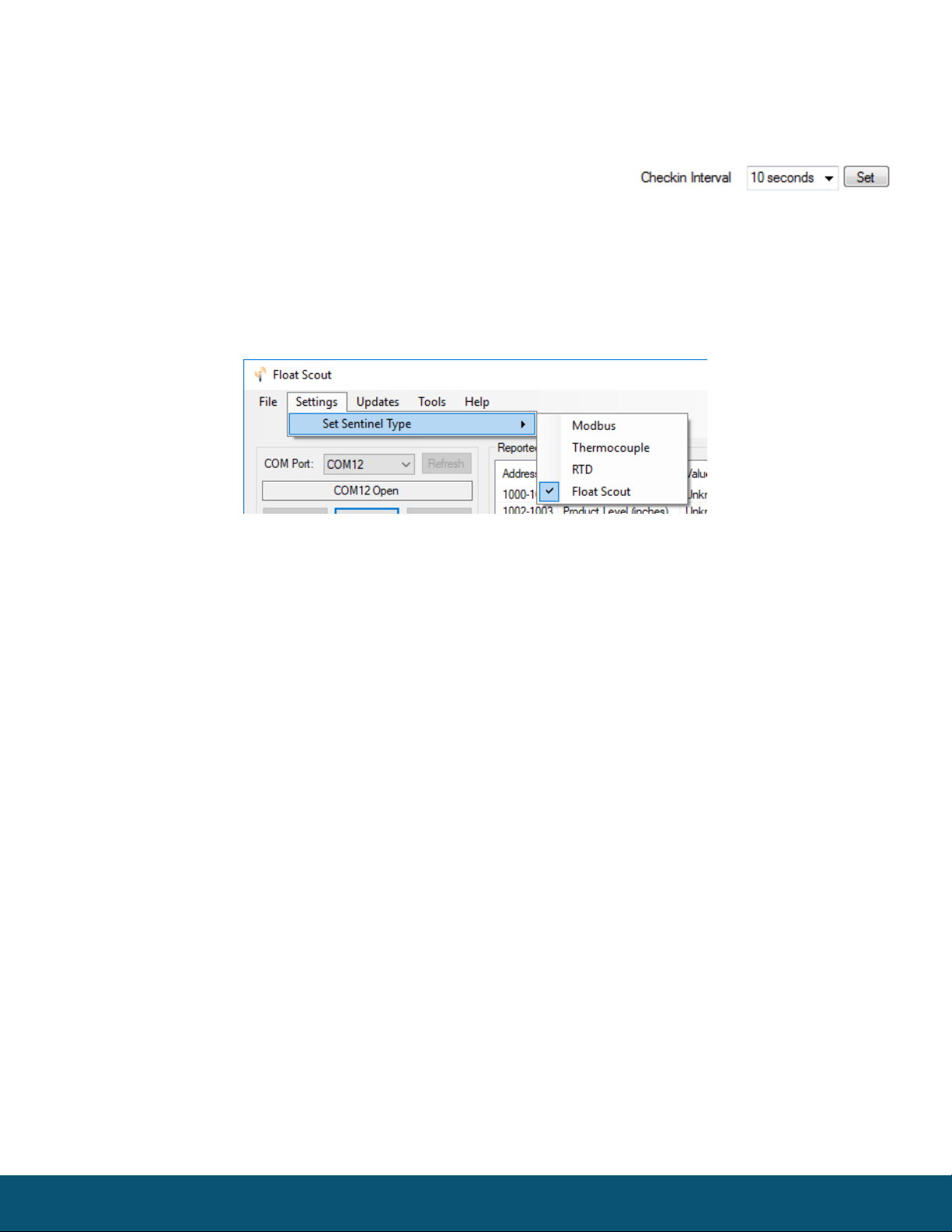
System Check-In Period
This setting controls how often the node will read the Modbus device and forward the register data to the
gateway.
Configuration
Since the Sentinel Float Stick uses a standard Sentinel Modbus Node with the Float Stick interface card it is
necessary to set the Sentinel type for Float Stick operation if it is in the default Modbus mode. To do this, select
Float Stick in the Set Sentinel Type option under the Settings pull down menu.

7
SignalFire Telemetry
Rev 1.2
Sensor Connections
Wiring Requirements
To ensure intrinsic safety is maintained it is required that the installer follow these guidelines when connecting
sensors to the SignalFire node. See pictures for proper wire routing examples.
-Strip the wires so that there is minimal exposed un-insulated wire when inserted into the screw
terminal.
-All wiring should be neat and orderly.
8
SignalFire Telemetry
Rev 1.2
Float Stick Connection
The Float Stick interface board is plugged into the Modbus connector on the Sentinel and has a 3-position
screw terminal block that is labeled with the wire colors from the Float Stick. Connect the Red, White and Black
wires to the correct terminals.
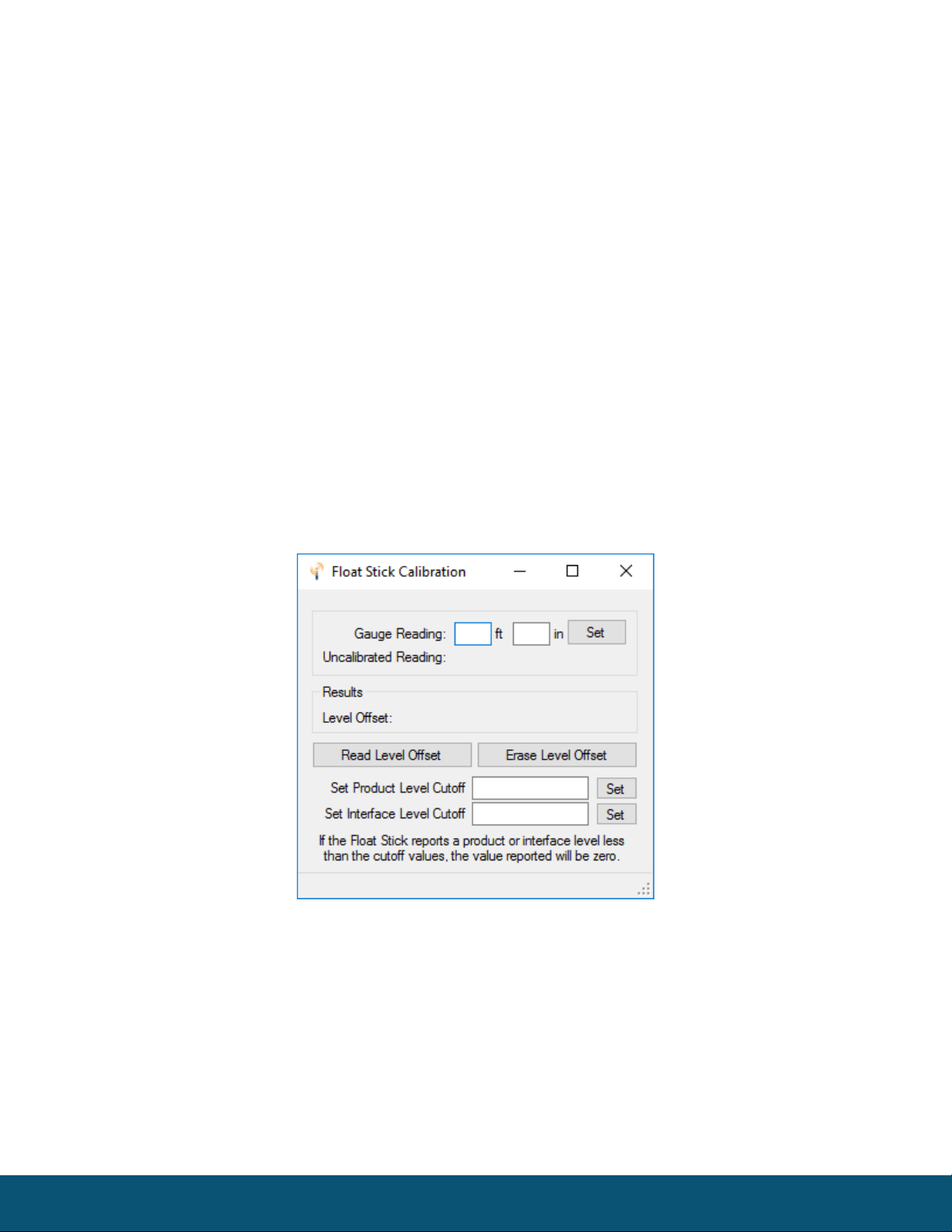
Float Stick Calibration Settings
After the Float Stick System is installed in a tank it will be necessary to calibrate the system to compensate for
the exact position of the device relative to the fluid level.
To calibrate the Float Stick System to match the level gauged in a tank, open the Float Stick Calibration
window from the Tools menu and enter the measured tank level in feet and inches and click Set. This will save
an offset value that will be applied to both the level and interface (for two float systems).
Optionally a “Level Cutoff” setting can be set for the product and/or level readings. Any reading at or below
the configured cutoff setting will be reported as zero. This is useful as the float cannot reach the actual bottom
of the tank due to the weight and required spacing.

9
SignalFire Telemetry
Rev 1.2
Remote Modbus Register Mapping
The Sentinel Node sends data to a SignalFire Telemetry Modbus Gateway. The data that is sent to
the gateway is available at the gateway in registers where it can then be read by a Modbus RTU.
The following data is sent to the Gateway:
Register Number
Register
Address
(offset)
Description
41001-41002
1000-1001
Float Stick Span (inches)
41003-41004
1002-1003
Product Level (inches)
41005-41006
1004-1005
Interface Level (inches
41007-41008
1006-1007
Temperature 1 (°C)
41009-41010
1008-1009
Temperature 2 (°C)
41011-41012
1010-1011
Temperature 3 (°C)
41013-41014
1012-1013
Temperature 4 (°C)
41015-41016
1014-1015
Temperature 5 (°C)
41017-41018
1016-1017
Communication Status (0=No errors; 1=No data received; 2=Only partial
data received; 3=Checksum error; 4=Float Stick internal error reported
49987
9986 or 65523
Low Battery Alarm (0 = battery above 3.0V, 1 = battery below 3.0V)
49988
9987 or 65524
Major revision number for the mainboard
49989
9988 or 65525
Minor revision number for the mainboard
49990
9989 or 65526
Major revision number for the radio
49991
9990 or 65527
Minor revision number for the radio
49992
9991 or 65528
High 16 bits of SFTS node address
49993
9992 or 65529
Low 16 bits of SFTS node address (the radio ID)
49994
9993 or 65530
Slave ID readback
49995
9994 or 65531
Received signal strength of last packet from the slave
49996
9995 or 65532
Battery voltage of the Sentinel-Float Stick, in millivolts
49997
9996 or 65533
Minutes until this slave will time out, unless new data is received
49998
9997 or 65534
Number of registers cached for this slave device
49999
9998 or 65535
Remote device type. 0x34 (52) for Sentinel Float Stick
Float Sticks configured for only one float will return 0 for the Interface Level. Float Sticks with only one
temperature sensor will return the same temperature reading for all five temperatures.
If there is any error communicating with the Float Stick all readings will return 999.9999.
Additionally, if there is an error the communication status register will contain additional information on the
cause of the error.
10
SignalFire Telemetry
Rev 1.2
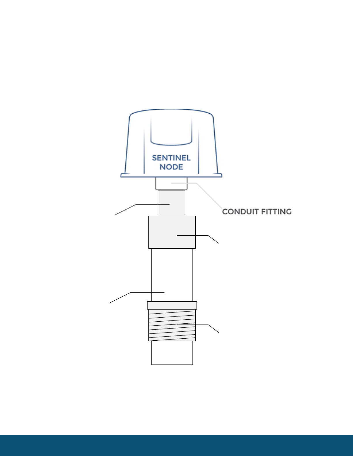
Mounting and Care
The unit comes with a watertight ½” NPT conduit fitting on the bottom mounting plate. The
Sentinel Float Stick also includes 2 NPT fittings for adapting the Sentinel to the Float Stick. Mounting is
pictured below.
In addition, a ¾” NPT compression fitting is supplied for mounting the assembly to a tank.
Sentinel Mounting to Float Stick
½” NPT Nipple
(supplied)
½” to ¾” NPT Adapter
(supplied)
FLOAT STICK
1" NPT Compression
Fitting
(ordered separately)
11
SignalFire Telemetry
Rev 1.2
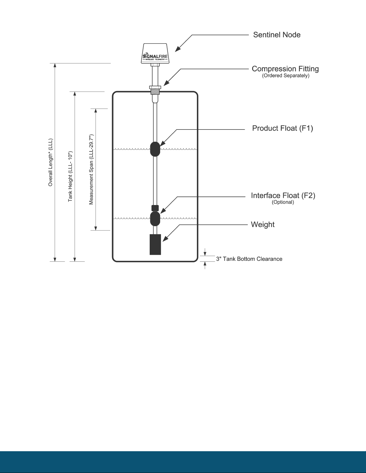
Note: For dual float systems the lower float is marked with an “I” and the upper float is marked with a
“P”. For dual floats the foam float spacer is required between the floats.

12
SignalFire Telemetry
Rev 1.2
Internal Lithium Battery Replacement
Battery Packs can be changed with the node in place.
1Open the cover from the enclosure.
2Unplug the battery from the PCB, by depressing the locking clip on the connector.
3Loosen the screw holding the battery door and slide the old battery out.
4Slide in the new battery pack and tighten the battery door screw.
5Connect the battery to the main PCB battery connector.
6Install the enclosure cover.
WARNING: Use of any battery other than the SignalFire part number 810-0008-02 will
impair the protection provided by the equipment.
WARNING: If the internal battery is installed the external solar battery system or other
power source may not be connected!
Cleaning Instructions
The outside of the enclosure may be cleaned with water, mild soap, and a damp cloth as needed. High pressure
washing is not recommended.
WARNING: Electrostatic Discharge Hazard! Care must be taken to avoid the potential of
creating a change on the enclosure or antenna. Do not wipe with a dry cloth. Do not brush
against the enclosure with clothing or gloves.

13
SignalFire Telemetry
Rev 1.2
Configuration / Debug
WARNING: Only connect to the debug port in a safe area!
Debug and configuration information is available if a connection is made via the debug port on the main
board. A USB converter cable (available from SignalFire) must be used for this interface.
Debug and advanced configuration may be done using the SignalFire Toolkit PC application.
Technical Support and Contact Information
SignalFire Telemetry
140 Locke Dr, Suite B
Marlborough, MA 01752
(978) 212-2868
Revision
Date
Changes/Updates
1.0
12/15/15
Initial release
1.1
8/3/16
Updated diagrams, added section on encryption
1.2
2/8/19
Updated screenshots, descriptions
Minor format updates

14
SignalFire Telemetry
Rev 1.2
APPENDIX - FCC and IC Statements
Changes or modifications not expressly approved by SignalFire Telemetry, Inc could void the user’s authority to operate the equipment.
This device complies with Part 15 of the FCC Rules. Operation is subject to the following two conditions: (1) this device may not cause harmful
interference, and (2) this device must accept any interference received, including interference that may cause undesired operation.
This equipment has been tested and found to comply with the limits for a Class B digital device, pursuant to Part 15 of the FCC Rules. These limits
are designed to provide reasonable protection against harmful interference in a residential installation. This equipment generates, uses and can radiate
radio frequency energy and, if not installed and used in accordance with the instructions, may cause harmful interference to radio communications.
However, there is no guarantee that interference will not occur in a particular installation. If this equipment does cause harmful interference to radio
or television reception, which can be determined by turning the equipment off and on, the user is encouraged to try to correct the interference by one
of the following measures:
-- Reorient or relocate the receiving antenna.
-- Increase the separation between the equipment and receiver.
-- Connect the equipment into an outlet on a circuit different from that to which the receiver is connected.
-- Consult the dealer or an experienced radio/TV technician for help.
Only the supplied coil antenna (Part number 810-0012-01) which is permanently soldered to the PCB may be used. This antenna has a maximum
gain of 3dB.
WARNING!
FCC and IC Radiation Exposure Statement:
This equipment complies with FCC’s and IC’s RF radiation exposure limits set forth for an uncontrolled environment under the following conditions:
1. This equipment should be installed and operated such that a minimum separation distance of 20cm is maintained between the radiator
(antenna) & user’s/nearby person’s body at all times.
2. This transmitter must not be co-located or operating in conjunction with any other antenna or transmitter.
Under Industry Canada regulations, this radio transmitter may only operate using an antenna of a maximum (or lesser) gain approved for this
transmitter by Industry Canada. To reduce potential radio interference to other users, the antenna type and its gain should be so chosen that the
equivalent isotropically radiated power (e.r.i.p.) is not more than that necessary for successful communication.
Table of contents
Other SignalFire Recording Equipment manuals

Popular Recording Equipment manuals by other brands


White Rodgers
White Rodgers 1F98EZ-1621 Homeowner user guide

Brotech Electronics
Brotech Electronics Mini Midi Sequencer+ user manual

Yamaha
Yamaha QX-3 owner's manual

Monitor Technologies
Monitor Technologies SiloPatrol Installation & operation

auray
auray RF-DT-10 owner's manual

Proximitar
Proximitar X27 user manual