Signametrics SM2060 User manual

Operator's Manual
Model SM2060 7½ Digit Digital PCI Multimeter
Model SMX2060 7½ Digit Digital PXI Multimeter
Model SM2064 7½ Digit High Work Load PCI Digital Multimeter
Model SMX2064 7½ Digit High Work Load PXI Digital Multimeter
Signametrics Corporation
February 2005
Rev 1.1

Signametrics 2
CAUTION
In no event shall Signametrics or its Representatives are liable for any consequential damages whatsoever
(including, without limitation, damages for loss of business profits, business interruption, loss of business
information, or other loss) arising out of the use of or inability to use Signametrics products, even if Signametrics
has been advised of the possibility of such damages. Because some states do not allow the exclusion or limitation of
liability for consequential damages, the above limitations may not apply to you.
©2004 Signametrics Corp. Printed in the USA. All rights reserved. Contents of this publication must not be
reproduced in any form without the permission of Signametrics Corporation.

3 Signametrics
TABLE OF CONTENTS
1.0 INTRODUCTION.................................................................................................................................................8
1.1 S
AFETY
C
ONSIDERATIONS
..........................................................................................................................8
1.2 M
INIMUM
R
EQUIREMENTS
.........................................................................................................................9
1.3 F
EATURE
S
ET
.............................................................................................................................................9
2.0 SPECIFICATIONS.............................................................................................................................................10
2.1 DC V
OLTAGE
M
EASUREMENT
.................................................................................................................10
2.2 DC C
URRENT
M
EASUREMENT
.................................................................................................................10
2.3 R
ESISTANCE
M
EASUREMENTS
..................................................................................................................11
2.3.1 2-wire.....................................................................................................................................11
2.3.2 4-wire.....................................................................................................................................11
2.3.3 6-wire Guarded Resistance Measurement (SM2064)............................................................11
2.3.4 Extended Resistance Measurements (SM2064) .....................................................................12
2.4 AC V
OLTAGE
M
EASUREMENTS
...............................................................................................................12
2.4.1 AC Voltage True RMS Measurement.....................................................................................12
2.4.2 AC Peak-to-Peak Measurement (SM2064)............................................................................14
2.4.3 AC Crest Factor Measurement (SM2064) .............................................................................15
2.4.4 AC Median Value Measurement (SM2064)...........................................................................15
2.5 AC C
URRENT
M
EASUREMENT
, T
RUE
RMS .............................................................................................15
2.6 L
EAKAGE
M
EASUREMENT
(SM2064) ......................................................................................................16
2.7 RTD T
EMPERATURE
M
EASUREMENT
(SM2064) .....................................................................................16
2.8 T
HERMOCOUPLE
T
EMPERATURE
M
EASUREMENT
(SM2064) ...................................................................17
2.9 A
DDITIONAL
C
OMPONENT
M
EASUREMENT
C
APABILITY
..........................................................................17
2.9.1 Diode Characterization .........................................................................................................17
2.9.2 Capacitance, Ramp Method (SM2064)..................................................................................17
2.9.3 Capacitance, In-Circuit Method (SM2064)..........................................................................19
2.9.4 Inductance Measurement (SM2064)......................................................................................19
2.10 T
IME
M
EASUREMENTS
...........................................................................................................................19
2.10.1 Threshold DAC ....................................................................................................................19
2.10.2 Frequency and Period Measurement...................................................................................20
2.10.3 Duty Cycle Measurement.....................................................................................................20
2.10.4 Pulse Width..........................................................................................................................20
2.10.5 Totalizer...............................................................................................................................21
2.11 T
RIGGER
F
UNCTIONS
.............................................................................................................................21
2.11.1 External Hardware Trigger (at DIN-7 connector) ..............................................................21
2.11.2 Analog Threshold Trigger....................................................................................................21
2.11.3 Delayed Hardware Trigger..................................................................................................21
2.12 M
EASUREMENT
A
PERTURE AND
R
EAD
I
NTERVAL
..................................................................................21
2.13 S
OURCE
F
UNCTIONS
(SMX2064)...........................................................................................................23
2.13.1 DC Voltage Source ..............................................................................................................24
2.13.2 AC Voltage Source...............................................................................................................24
2.13.3 DC Current Source..............................................................................................................24
2.14 A
CCURACY
N
OTES
.................................................................................................................................24
2.15 O
THER
S
PECIFICATIONS
.........................................................................................................................25
3.0 GETTING STARTED.........................................................................................................................................27
3.1 S
ETTING THE
DMM .................................................................................................................................27
3.2 I
NSTALLING THE
DMM M
ODULE
.............................................................................................................27
3.3 I
NSTALLING THE
S
OFTWARE
....................................................................................................................27
3.4 DMM I
NPUT
C
ONNECTORS
......................................................................................................................28
3.5 S
TARTING THE
C
ONTROL
P
ANEL
..............................................................................................................29
3.6 U
SING THE
C
ONTROL
P
ANEL
....................................................................................................................30
4.0 DMM OPERATION AND MEASUREMENT TUTORIAL...........................................................................32

Signametrics 4
4.1 V
OLTAGE
M
EASUREMENT
........................................................................................................................32
4.1.1 DC Voltage Measurements ....................................................................................................32
4.1.2 True RMS AC Voltage Measurements ...................................................................................32
4.1.3 AC Peak-to-Peak and Crest Factor (SM2064)......................................................................33
4.1.4 AC Median Value Measurement (SM2064)...........................................................................33
4.2 C
URRENT
M
EASUREMENTS
......................................................................................................................33
4.2.1 Extended DC Current Measurements (SM2064) ...................................................................34
4.2.2 Improving DC Current Measurements ..................................................................................34
4.2.3 DC Current Measurements at a specific voltage...................................................................34
4.3 R
ESISTANCE
M
EASUREMENTS
..................................................................................................................35
4.3.1 2-Wire Ohm Measurements ...................................................................................................35
4.3.2 4-Wire Ohm Measurements ...................................................................................................35
4.3.3 Using Offset Ohms function (SM2064)..................................................................................36
4.3.4 6-wire Guarded Resistance Measurement (SM2064)............................................................36
4.3.5 Extended Resistance Measurements (SM2064) .....................................................................37
4.3.6 Effects of Thermo-Voltaic Offset............................................................................................38
4.3.7 Guarding High Value Resistance Measurements (SM2064) .................................................39
4.4 L
EAKAGE
M
EASUREMENTS
(SM2064).....................................................................................................39
4.5 M
EASUREMENT
T
IMING
...........................................................................................................................40
4.5.1 Aperture.................................................................................................................................40
4.5.2 Read Interval..........................................................................................................................40
4.6 RTD T
EMPERATURE
M
EASUREMENT
(SM2064) .....................................................................................42
4.7 I
NTERNAL
T
EMPERATURE
(SM2064) .......................................................................................................42
4.8 D
IODE
C
HARACTERIZATION
.....................................................................................................................42
4.9 C
APACITANCE
M
EASUREMENT
(SM2064) ...............................................................................................43
4.10 I
N
-C
IRCUIT
C
APACITANCE
M
EASUREMENT
(SM2064) ..........................................................................43
4.11 I
NDUCTANCE
M
EASUREMENT
(SM2064) ...............................................................................................44
4.12 C
HARACTERISTIC
I
MPEDANCE
M
EASUREMENT
(SM2064).....................................................................44
4.13 T
RIGGER
O
PERATION
.............................................................................................................................44
4.13.1 External Hardware Trigger.................................................................................................44
4.13.2 Analog Threshold Trigger....................................................................................................45
4.13.3 Software Generated Triggered Operations..........................................................................45
4.14 F
REQUENCY AND
T
IME
M
EASUREMENTS
...............................................................................................47
4.14.1 Threshold DAC ....................................................................................................................47
4.14.2 Frequency and Period Measurements .................................................................................48
4.14.3 Duty Cycle Measurement.....................................................................................................48
4.14.4 Pulse Width..........................................................................................................................48
4.14.5 Totalizer Event Counter.......................................................................................................48
4.15 S
OURCING
F
UNCTIONS
(SM2064)..........................................................................................................49
4.15.1 DC Voltage Source ..............................................................................................................49
4.15.2 AC Voltage Source...............................................................................................................50
4.15.3 DC Current Source..............................................................................................................51
4.15.4 Source Current - Measure Voltage......................................................................................51
4.16 I
NTERFACING TO THE
SM4040
SERIES
R
ELAY
S
CANNERS
......................................................................51
4.16.1 Triggering the SM2060 DMM’s...........................................................................................51
4.16.2 Multiplexing with the SM2060 DMM’s................................................................................52
4.16.3 Interface Commands and Timing.........................................................................................52
4.17 M
EASURING
T
EMPERATURE WITH
T
HERMOCOUPLES
.............................................................................53
4.18 U
SING THE
PXI
BUS
T
RIGGER
F
ACILITIES
(SMX2064)..........................................................................53
4.18.1 Selecting PXI Trigger Outputs.............................................................................................53
4.18.2 Selecting PXI Trigger Inputs ...............................................................................................54
5.0 WINDOWS INTERFACE..................................................................................................................................55
5.1 D
ISTRIBUTION
F
ILES
................................................................................................................................55
5.2 U
SING THE
SM2060 D
RIVER
W
ITH
C++
OR
S
IMILAR
S
OFTWARE
............................................................57
5.2.1 Multiple Card Operations under Windows............................................................................57
5.3 V
ISUAL
B
ASIC
F
RONT
P
ANEL
A
PPLICATION
.............................................................................................58
5.3.1 Visual Basic Simple Application............................................................................................59
5.4 W
INDOWS
DLL D
EFAULT
M
ODES AND
P
ARAMETERS
.............................................................................60

5 Signametrics
5.5 U
SING THE
SM2060 DLL
WITH
L
AB
W
INDOWS
/CVI®............................................................................60
5.6 W
INDOWS
C
OMMAND
L
ANGUAGE
...........................................................................................................60
DMMArmAnalogTrigger ................................................................................................................60
DMMArmTrigger............................................................................................................................62
DMMBurstBuffRead .......................................................................................................................63
DMMBurstRead..............................................................................................................................64
DMMCalibrate................................................................................................................................65
DMMCleanRelay ............................................................................................................................66
DMMClearBuffer............................................................................................................................67
DMMClearMinMax ........................................................................................................................67
DMMClosePCI ...............................................................................................................................68
DMMDelay .....................................................................................................................................68
DMMDelayedTrigger .....................................................................................................................69
DMMDisableTrimDAC...................................................................................................................70
DMMDisArmTrigger ......................................................................................................................70
DMMDutyCycleStr .........................................................................................................................71
DMMErrString................................................................................................................................71
DMMFrequencyStr.........................................................................................................................72
DMMGetACCapsR .........................................................................................................................73
DMMGetAperture...........................................................................................................................73
DMMGetBufferSize.........................................................................................................................74
DMMGetBusInfo.............................................................................................................................74
DMMGetCalDate............................................................................................................................75
DMMGetdB.....................................................................................................................................76
DMMGetdBStr................................................................................................................................76
DMMGetCJTemp............................................................................................................................77
DMMGetDeviation .........................................................................................................................77
DMMGetDeviatStr..........................................................................................................................78
DMMGetFuncRange.......................................................................................................................78
DMMGetFunction...........................................................................................................................79
DMMGetGrdVer.............................................................................................................................79
DMMGetHwVer..............................................................................................................................80
DMMGetID.....................................................................................................................................80
DMMGetManDate..........................................................................................................................81
DMMGetMax..................................................................................................................................82
DMMGetMaxStr .............................................................................................................................82
DMMGetMin...................................................................................................................................83
DMMGetMinStr..............................................................................................................................83
DMMGetRange...............................................................................................................................84
DMMGetReadInterval ....................................................................................................................85
DMMGetSourceFreq ......................................................................................................................85
DMMGetTCType.............................................................................................................................86
DMMGetTriggerInfo.......................................................................................................................86
DMMGetType .................................................................................................................................87
DMMGetVer ...................................................................................................................................87
DMMInit .........................................................................................................................................88
DMMIsAutoRange ..........................................................................................................................88
DMMIsInitialized............................................................................................................................89
DMMIsRelative...............................................................................................................................89
DMMOpenPCI................................................................................................................................90
DMMOpenCalACCaps...................................................................................................................90
DMMOpenTerminalCal..................................................................................................................91
DMMPeriodStr ...............................................................................................................................92
DMMPolledRead ............................................................................................................................92
DMMPolledReadCmd.....................................................................................................................93
DMMPolledReadStr........................................................................................................................94
DMMQuickInit................................................................................................................................94
DMMRead.......................................................................................................................................95
DMMReadBuffer.............................................................................................................................96
DMMReadBufferStr........................................................................................................................97

Signametrics 6
DMMReadCJTemp .........................................................................................................................97
DMMReadCrestFactor ...................................................................................................................98
DMMReadDutyCycle......................................................................................................................99
DMMReadFrequency......................................................................................................................99
DMMReadInductorQ....................................................................................................................100
DMMReadMeasurement...............................................................................................................101
DMMReadMedian.........................................................................................................................101
DMMReadNorm............................................................................................................................102
DMMReadPeakToPeak.................................................................................................................102
DMMReadPeriod..........................................................................................................................103
DMMReadStr................................................................................................................................104
DMMReadTotalizer ......................................................................................................................105
DMMReadWidth...........................................................................................................................105
DMMReady...................................................................................................................................106
DMMSetACCapsDelay .................................................................................................................106
DMMSetACCapsLevel..................................................................................................................107
DMMSetACVSource .....................................................................................................................107
DMMSetAperture..........................................................................................................................108
DMMSetAutoRange ......................................................................................................................109
DMMSetBuffTrigRead ..................................................................................................................109
DMMSetCapsAveSamp.................................................................................................................110
DMMSetCJTemp...........................................................................................................................111
DMMSetCompThreshold ..............................................................................................................112
DMMSetCounterRng.....................................................................................................................112
DMMSetDCISource......................................................................................................................113
DMMSetDCVSource.....................................................................................................................114
DMMSetFastRMS.........................................................................................................................115
DMMSetFuncRange......................................................................................................................115
DMMSetFunction..........................................................................................................................116
DMMSetInductFreq......................................................................................................................116
DMMSetOffsetOhms.....................................................................................................................117
DMMSetPXITrigger......................................................................................................................117
DMMSetRange..............................................................................................................................118
DMMSetReadInterval...................................................................................................................119
DMMSetReference........................................................................................................................119
DMMSetRelative...........................................................................................................................120
DMMSetRTD ................................................................................................................................121
DMMSetSensorParams.................................................................................................................122
DMMSetSourceMode....................................................................................................................122
DMMSetSync ................................................................................................................................123
DMMSetTCType ...........................................................................................................................124
DMMSetTempUnits.......................................................................................................................124
DMMSetTrigPolarity....................................................................................................................125
DMMSetTrigRead.........................................................................................................................125
DMMSetTrimDAC ........................................................................................................................126
DMMStartTotalizer.......................................................................................................................127
DMMStopTotalizer .......................................................................................................................128
DMMTerminate.............................................................................................................................128
DMMTrigger.................................................................................................................................129
DMMTriggerBurst........................................................................................................................130
DMMWidthStr...............................................................................................................................131
5.7 C
ALIBRATION
S
ERVICE
C
OMMANDS
......................................................................................................133
AC_zero ........................................................................................................................................133
DMMLoadCalFile.........................................................................................................................133
GetGain.........................................................................................................................................134
GetOffset.......................................................................................................................................134
SetFcomp ......................................................................................................................................135
SetOffset........................................................................................................................................136
Linearize_AD................................................................................................................................136
Read_ADcounts ............................................................................................................................137

7 Signametrics
5.8 M
AINTANANCE
C
OMMANDS
..................................................................................................................138
GrdXingTest..................................................................................................................................138
5.7 E
RROR
C
ODES
........................................................................................................................................138
5.8 W
ARNING
C
ODES
...................................................................................................................................139
6.0 MAINTENANCE ..............................................................................................................................................139
6.1 P
ERFORMANCE
T
ESTS
............................................................................................................................141
6.2 DC V
OLTAGE
T
EST
................................................................................................................................141
6.3 R
ESISTANCE
T
EST
, 2-
WIRE
.....................................................................................................................142
6.4 R
ESISTANCE
T
EST
, 4-
WIRE
.....................................................................................................................143
6.5 AC V
OLTAGE
T
EST
................................................................................................................................144
6.6 DC C
URRENT
T
EST
................................................................................................................................145
6.7 AC C
URRENT
T
EST
................................................................................................................................146
N
OTE
: S
OME RANGES APPLY TO
2064
ONLY
. P
LEASE REFER TO CHAPTER
2.0 (S
PECIFICATION
). .................146
6.8 C
APACITANCE
T
EST
(SM2064
ONLY
) ....................................................................................................147
6.8 I
NDUCTANCE
T
EST
(SM2064
ONLY
) ......................................................................................................148
6.9 F
REQUENCY
C
OUNTER
T
EST
( SM2064
ONLY
) ......................................................................................149
6.10 C
ALIBRATION
.......................................................................................................................................150
7.0 WARRANTY AND SERVICE.........................................................................................................................152
8.0 ACCESSORIES.................................................................................................................................................152

1.0 Introduction
Congratulations! You have purchased a Personal Computer (PC) Plug-in instrument with analog and systems
performance that rivals the best, all-in-one box, instruments. The SM2060 and SMX2064 Digital Multimeters
(DMM’s) are easy to setup and use, have sophisticated analog and digital circuitry to provide very repeatable
measurements, and are protected to handle any unexpected situations your measurement environment may
encounter. To get years of reliable service from these DMM’s, please take a few moments and review this manual
before installing and using this precision instrument.
This manual describes the SM2060 and SM2064 DMM’s. The SMX2060 is identical to the SM2060 and the
SMX2064 is identical to the SM2064. The only difference is the bus type. The SM206X is a PCI module, while the
SMX206X is a PXI/cPCI module.
Note: In this manual, all references made to the "SM2060" are applicable to the SMX2060, and references to the
“SM2064” are applicable to the SMX2064. References to “DMM” apply to the SM2060, SMX2060, SM2064 and
SMX2064. Features unique to the SM2064 will be identified as such.
1.1 Safety Considerations
Safety Considerations
The SM2060 series of DMM’s is capable of measuring up to 300 VDC or 250 VAC across the Volt HI
and LO terminals, and can also measure common mode signals that "float" the DMM above EARTH
ground by up to 300 VDC or 250 VAC. When making common mode measurements, the majority of the
circuits inside the DMM are at the common mode voltage. These voltages can be lethal and can KILL!
During and after installing your DMM, check to see that there are no wires or ribbon cables from
your PC trapped inside the DMM.
The DMM comes installed with four shields (bottom, top and two edge strips) that must not be removed
for performance as well as safety reasons. Removal of these shields and/or improper assembly of the
shields can result in lethal voltages occurring within your PC. Be sure to check your installation before
closing the cover on your personal computer.
Warning
Check to see that no loose wires or ribbon cables infringe upon any of the internal circuits of the
DMM, as this may apply measurement voltages to your computer, causing electrocution and/or
damage to your computer!
To avoid shock hazard, install the DMM only into a computer that has its power connector
connected to a power receptacle with an earth safety ground.
When making any measurements above 50 VDC or 40 VAC, only use Safety Test Leads. Examples
of these are the Signametrics Basic Test Leads and Deluxe Test Leads, offered as an accessory with the
Signametrics DMM’s.
Signametrics 8

9 Signametrics
1.2 Minimum Requirements
The SM2060 series of system DMM’s are precision plug-in modules that are compatible with IBM type personal
computers (PCs), PXI and cPCI chassis. It requires as a minimum a Pentiums computer. They require a half-length
expansion slot on the PCI bus or 3U PXI slot. A mouse must be installed when controlling the DMM from the
Windows Control Panel. The SM2060 comes with a Windows' DLL, for operation with Windows' Version
95/98/Me/2000/XP and NT4.0.
1.3 Feature Set
The base unit, the SM2060, has traditional 7-1/2 digit features and it can be used as a general purpose DMM, where
accuracy and speed are important. The High Workload Multi Function SM2064 adds timing, capacitance,
inductance, sourcing and a lot more speed. With its specialized measurements, it can replace some costly
instruments, shrinking the size and cost of a test system.
SM2060 and SM2064 7½ Digit DMM’s feature table:
Function SM/SMX2060
DMM SM/SMX2064
High Workload
DMM
DCV five ranges 240mV to 330V √√
ACV five ranges 240mV to 330V √√
2-Wire Ohms, six ranges 240 Ωto 24 MΩ√√
4-Wire Ohms, six ranges 240 Ωto 24 MΩ√√
DC current, four ranges 2.4 mA to 2.4 A √√
AC current, four ranges 2.4 mA to 2.4 A √√
Diode V/I characteristics at 100 ηA to 1mA √√(plus 10mA)
Auto range, Relative √√
Min/Max, dB and percent deviation functions √√
On board measurement buffer √√
External and threshold trigger √√
Thermocouples type;
B, E, J, K, N, R, S, T
√√
High Dynamic range; +24,000,000 counts
√√
Frequency / Period measurement √√
Measurement rate: 0.2 to 1,400/sec √√
Measurement rate: to 20,000/sec √
Capacitance, ramp type, eight ranges, 1 nF to 10 mF √
Capacitance, In-Circuit method five ranges, 24nF to 2.4mF √
Inductance, six ranges 33 µH to 3.3 H √
Internal DMM temperature sensor √
Offset Ohms √
Temperature types pt385, 3911, 3916, 3926, Copper, variable Ro √
Pulse width, pos./neg., & duty cycle √
Totalizer/event counter √
Variable threshold DAC; all timing measure. √
Peak to Peak, Crest factor, Median √
Six wire Ohms (with force/sense) √
DCV source to ±10.0 V √
ACV source 0 to 20 V pk-pk, 2 Hz to 75 KHz √
DC current source, 1 nA to 12.5 mA √
Leakage measurement to ±10.0V three ranges 240nA, 2.4uA, 25uA √
Expanded ranges √
2-Wire Ohms two additional ranges 24 Ωand 240 MΩ√
4-Wire Ohms additional range 24 Ω√
Resistance with V&I limits (to 10GΩ) √
DC Current four additional ranges 240nA, 2.4µA, 24µA, 240µA √

Signametrics 10
2.0 Specifications
The following specifications are based on both, verification of large number of units as well as
mathematical evaluation. They should be considered under the environment specified.
It is important to note that a DMM specified range is expressed as a numeric value indicating the highest
absolute voltage that can be measured. The lowest value that can be detected is expressed by the
corresponding resolution for the range.
2.1 DC Voltage Measurement
Input Characteristics
• Input Resistance 240 mV, 2.4 V Ranges: >10 GΩ, with typical leakage of 50pA
• Input Resistance 24 V, 240 V, 330V Ranges: 10.00 MΩ
Accuracy ± (% of reading + Volts) [1]
Range Full Scale
7-½ Digits
Resolution 24 hours
23°C ±1°C
90 Days
23°C ±5°C
One Year 23°C
±5°C
240 mV 240.00000 mV 10 ηV 0.003 + 1 µV 0.004 + 1.5 µV 0.005 + 2 µV
2.4 V 2.4000000 V 100 ηV 0.002 + 3 µV 0.0025 + 5 µV 0.003 + 10 µV
24 V 24.000000 V 1 µV 0.003 + 150 µV 0.004 + 250 µV 0.005 + 300 µV
240 V 240.00000 V 10 µV0.004 + 200 µV 0.005 + 300 µV 0.006 + 0.5 mV
330 V 330.00000 V 10 µV0.005 + 250 µV 0.01+ 400 µV 0.015 + 0.7 mV
[1] With Aperture set to 0.5 Sec, and within one hour from Self Calibration (S-Cal).
For resolution at smaller Apertures, see the following table. Use this table for DC Volts, DC current
and Resistance measurements.
Measurement Aperture
SM2060, SM2064
Maximum reading
rate
Resolution
0.5 s <Aperture 2 / second 7-1/2 digits 25 bits
10 ms <Aperture 100 / second 6-1/2 digits 22 bits
625µs <Aperture 1200 / second 5-1/2 digits 18 bits
2.5us <Aperture [2] 20,000 / second [2] 4-1/2 digits 14 bits
[2] Available only with the SM2064.
DCV Noise Rejection Normal Mode Rejection, at 50, 60, or 400 Hz ± 0.5%, is better than 95 dB
for apertures of 0.160s and higher. Common Mode Rejection (with 1 kΩlead imbalance) is better
than 120 dB for these conditions.
2.2 DC Current Measurement
Input Characteristics
• Number of shunts Five in SM2064, two in the SM2060
• Protected with 2.5A Fast blow fuse
Accuracy ± (% of reading + Amps) [1]
Range Full Scale
6-½ Digits
Resolution Max Burden
Voltage
24 hours
23°C ±5°C
90 Days
23°C ±5°C
One Year 23°C
±5°C
240 ηA [2] 240.0000 ηA 0.1 pA 100 µV 0.07 + 40pA 0.1 + 45pA 0.17 + 60pA
2.4 µA [2] 2.400000 µA 1 pA 100 µV 0.05 + 70pA 0.08 + 90pA 0.21 + 150pA
24 µA [2] 24.00000 µA 10 pA 100 µV 0.05 + 400pA 0.08 + 600pA 0.13 + 0.8nA
240 µA [2] 240.000 µA 10 ηA 2.5mV 0.052 + 200 ηA 0.07 + 300 ηA 0.1 + 400 ηA
2.4 mA 2.40000 mA 10 ηA 25mV 0.05 + 300 ηA 0.06 + 400 ηA 0.07 + 550 ηA
24 mA 24.0000 mA 100 ηA 250mV 0.05 + 350 ηA 0.065 + 450 ηA 0.08 + 550 ηA
240 mA 240.000 mA 1 µA 55mV 0.05 + 50 µA 0.055 + 60 µA 0.065 + 80 µA
2.4 A 2.40000 A 10 µA 520mV 0.3 + 60 µA 0.4 + 70 µA 0.45 + 90 µA
[1] With Aperture set to 0.96 Sec, and within one hour from Zero (Relative control).
[2] Available only with the SM2064.

11 Signametrics
2.3 Resistance Measurements
2.3.1 2-wire
Accuracy ± (% of reading + Ω) [1]
Range [4] Full Scale
7 ½ Digits
Resolution Source
current
24 hours
23°C ±1°C
90 Days
23°C ±5°C
One Year
23°C ±5°C
24 Ω[3] 24.000000 Ω1 µΩ 10 mA 0.0038 + 1.4 mΩ[2] 0.005 + 1.6 mΩ[2] 0.008 + 2 mΩ[2]
240 Ω240.00000 Ω10 µΩ 1 mA 0.0037 + 4.5 mΩ[2] 0.0046 + 5 mΩ[2] 0.007 + 6 mΩ[2]
2.4 kΩ2.4000000 kΩ100 µΩ 1 mA 0.0023 + 28 mΩ0.004 + 32 mΩ0.006 + 33 mΩ
24 kΩ24.000000 kΩ1 mΩ100 µA 0.0025 + 300 mΩ0.004 + 330 mΩ0.006 + 350 mΩ
240 kΩ240.00000 kΩ10 mΩ10 µA 0.0055 + 3.2 Ω0.006 + 4 Ω0.007 + 5 Ω
2.4 MΩ2.4000000 MΩ100 mΩ1 µA 0.018 + 40 Ω0.03 + 50 Ω0.04 + 70 Ω
24 MΩ24.0000 MΩ100 Ω100 nA 0.12 + 400 Ω0.13 + 500 Ω0.2 + 600 Ω
240 MΩ[3] 240.000 MΩ1 kΩ10 nA 0.8 + 20 kΩ1.0 + 30 kΩ1.3 + 50 kΩ
[1] With Aperture set to 0.5 Sec, and within one hour from Self Calibration (S-Cal).
[2] Use of S-Cal and Relative to improve measurement floor.
[3] Ranges are only available with the SM2064.
[4] Test voltages are 2.4V max with the exception of the 24
Ω
and 240
Ω
ranges 240 mV.
2.3.2 4-wire
Accuracy ± (% of reading + Ω) [1]
Range [4] Full Scale
7 ½ Digits
Resolution Source
current
24 hours
23°C ±1°C
90 Days
23°C ±5°C
One Year
23°C ±5°C
24 Ω[3] 24.000000 Ω1 µΩ 10 mA 0.0038 + 0.7 mΩ[2] 0.005 + 0.8 mΩ[2] 0.008 + 1 mΩ[2]
240 Ω240.00000 Ω10 µΩ 1 mA 0.0037 + 3 mΩ[2] 0.0046 + 4 mΩ[2] 0.007 + 5 mΩ[2]
2.4 kΩ2.4000000 kΩ100 µΩ 1 mA 0.0023 + 28 mΩ0.004 + 32 mΩ0.006 + 33 mΩ
24 kΩ24.000000 kΩ1 mΩ100 µA 0.0025 + 300 mΩ0.004 + 330 mΩ0.006 + 350 mΩ
240 kΩ240.00000 kΩ10 mΩ10 µA 0.0055 + 3.2 Ω0.007 + 4 Ω0.007 + 5 Ω
2.4 MΩ2.4000000 MΩ100 mΩ1 µA 0.018 + 40 Ω0.03 + 50 Ω0.04 + 70 Ω
24 MΩ24.0000 MΩ100 Ω100 nA 0.12 + 400 Ω0.13 + 500 Ω0.2 + 600 Ω
[1] With Aperture set to 0.5 Sec, and within one hour from Self Calibration (S-Cal).
[2] Use of Relative to facilitate indicated floor (adder part of spec).
[3] 24 Ωrange only available with SM2064.
[4] Test voltages are 2.4V max with the exception of the 24
Ω
and 240
Ω
ranges 240 mV.
2.3.3 6-wire Guarded Resistance Measurement (SM2064)
This is an in-circuit forced guard measurement method, as implemented in ICT testers. Add this typical additional
error to the above specification.
Accuracy ± (% of reading + Ω)
Range Guard forced current One Year 23°C ±5°C [1]
24 Ω[3] 10 mA 0.3 + 4 mΩ
240 Ω1 mA 0.003 + 20 mΩ
2.4 kΩ1 mA 0.005 + 100 mΩ
24 kΩ100 µA 0.03 + 1 Ω
240 kΩ10 µA 0.35 + 10 Ω
24 MΩ1 µA 0.85 + 1000 Ω
[1] This table should be used in conjunction with the 2-wire and 4-wire table above.
Signametrics 12
2.3.4 Extended Resistance Measurements (SM2064)
Characteristics
• Test Voltage Adjustable between -10V and +10V in 5mV steps
Accuracy ± (% of reading + Amps) [1]
Range
Measurement range
Resol
ution
Current Limit [3] 90 Days
23°C ±5°C
One Year 23°C
±5°C
400kΩ
1kΩto 100MΩ
10Ω
25µA
0.2 +
50Ω
0.33 + 9
0Ω
4MΩ
10kΩto 1GΩ
100Ω
2.5µA
0.3 +
350Ω
0.43 +
550Ω
40MΩ
100kΩto 10GΩ
1kΩ
250nA
0.4 +
3kΩ
0.55 + 4.5k
Ω
[1] With Aperture set to 0.5 Sec, and within one hour from Zero (Relative control).
[2] Multiply “% of reading” by 1/Voltage Source for applied voltages below 1V
[3] Limit is reached when the test current exceeds the Current Limit, or it is below 0.04% of
this value.
2.4 AC Voltage Measurements
Input Characteristics
• Input Resistance 1 MΩ, shunted by < 300 pF, all ranges
• Max. Crest Factor 4 at Full Scale, increasing to 7 at Lowest Specified Voltage
• AC coupled Specified range: 10 Hz to 100 kHz
• Typical Settling time < 0.5 sec to within 0.1% of final value
• Typical Settling time Fast RMS < 0.05 sec to within 0.1% of final value
2.4.1 AC Voltage True RMS Measurement
Range Full Scale 7-½ Digits Lowest specified Voltage Resolution
240 mV 240.0000 mV 5 mV [1] 100 ηV
2.4 V 2.400000 V 10 mV 1 µV
24 V 24.00000 V 100 mV 10 µV
240 V 240.0000 V 1 V 100 µV
330 V 330.0000 V 2 V 100 µV
[1] Between 5 mV and 10 mV, add 100 µV additional errors to the accuracy table below.
[2] Signal is limited to 8x10
6
Volt Hz Product. For example, the largest frequency input at 250 V is
32 kHz, or 8x10
6
Volt x Hz.

13 Signametrics
AC Volts Accuracy with Fast RMS disabled (default).
With Fast RMS disabled, settling time to rated accuracy is within 0.5 s.
Accuracy ± (% of reading + Volts) [1]
Range Frequency 24 hours
23°C ±1°C
90 Days
23°C ±5°C
One Year
23°C ±5°C
10 Hz - 20 Hz 3.0 + 350 µV 3.1 + 380 µV 3.2 + 430 µV
20 Hz - 47 Hz 0.92 + 150 µV 0.93 + 170 µV 0.95 + 200 µV
47 Hz - 10 kHz 0.13 + 100 µV 0.14 + 110 µV 0.15 + 120 µV
10 kHz - 50 kHz 0.55 + 160 µV 0.6 + 200 µV 0.63 + 230 µV
240 mV
50 kHz - 100 kHz 5.3 + 350 µV 5.4 + 370 µV 5.6 + 400 µV
10 Hz - 20 Hz 3.0 + 2 mV 3.1 + 2.2 mV 3.2 + 2.5 mV
20 Hz - 47 Hz 0.93 + 1.3 mV 0.96 + 1.5 mV 1.0 + 1.7 mV
47 Hz - 10 kHz 0.05 + 1 mV 0.055 + 1.1 mV 0.065 + 1.2 mV
10 kHz - 50 kHz 0.62 + 1.2 mV 0.65 + 1.3 mV 0.70 + 1.5 mV
2.4 V
50 kHz - 100 kHz 5.1 + 1.5 mV 5.2 + 1.7 mV 5.3 + 2 mV
10 Hz - 20 Hz 3.0 + 14 mV 3.1 + 16 mV 3.3 + 20 mV
20 Hz - 47 Hz 0.93 + 12 mV 0.96 + 14 mV 1.0 + 16 mV
47 Hz - 10 kHz 0.06 + 10 mV 0.065 + 11 mV 0.073 + 13 mV
10 kHz - 50 kHz 0.31 + 18 mV 0.33 + 21 mV 0.35 + 25 mV
24 V
50 kHz - 100 kHz 2.0 + 30 mV 2.2 + 35 mV 2.4 + 40 mV
10 Hz - 20 Hz 3.0 + 140 mV 3.1 + 160 mV 3.3 + 200 mV
20 Hz - 47 Hz 0.93 + 120 mV 0.96 + 130 mV 1.0 + 150 mV
47 Hz - 10 kHz 0.04 + 100 mV 0.045 + 110 mV 0.06 + 130 mV
10 kHz - 50 kHz 0.32 + 150 mV 0.4 + 170 mV 0.45 + 200 mV
240 V
50 kHz - 100 kHz 2.5 + 200 mV 2.8 + 240 mV 3.2 + 300 mV
10 Hz - 20 Hz 3.0 + 200 mV 3.1 + 160 mV 3.3 + 200 mV
20 Hz - 47 Hz 1.0 + 180 mV 1.1 + 200 mV 1.1 + 250 mV
47 Hz - 10 kHz 0.05 + 150 mV 0.07 + 200 mV 0.08 + 230 mV
10 kHz - 50 kHz 0.34 + 200 mV 0.45 + 250 mV 0.5 + 300 mV
330 V
50 kHz - 100 kHz 2.5 + 270 mV 2.8 + 350 mV 3.2 + 400 mV
ACV Noise Rejection Common Mode rejection, for 50 Hz or 60 Hz with 1 kΩimbalance in either lead, is better
than 60 dB.
AC Volts Accuracy with Fast RMS enabled.

Signametrics 14
Fast RMS settles to rated accuracy within 50ms.
Accuracy ± (% of reading + Volts) [1]
Range Frequency 24 hours
23°C ±1°C
90 Days
23°C ±5°C
One Year
23°C ±5°C
350 Hz - 800 Hz 0.6 + 150 µV 0.65 + 170 µV 0.7 + 200 µV
800 Hz - 10 kHz 0.13 + 100 µV 0.14 + 110 µV 0.15 + 120 µV
10 kHz - 50 kHz 0.55 + 160 µV 0.6 + 200 µV 0.63 + 230 µV
240 mV
50 kHz - 100 kHz 5.3 + 350 µV 5.4 + 370 µV 5.6 + 400 µV
350 Hz - 800 Hz 0.93 + 1.3 mV 0.96 + 1.5 mV 1.0 + 1.7 mV
800 Hz - 10 kHz 0.068 + 1 mV 0.075 + 1.1 mV 0.08 + 1.2 mV
10 kHz - 50 kHz 0.62 + 1.2 mV 0.65 + 1.3 mV 0.70 + 1.5 mV
2.4 V
50 kHz - 100 kHz 5.1 + 1.5 mV 5.2 + 1.7 mV 5.3 + 2 mV
350 Hz - 800 Hz 0.93 + 12 mV 0.96 + 14 mV 1.0 + 16 mV
800 Hz - 10 kHz 0.065 + 10 mV 0.068 + 11 mV 0.073 + 13 mV
10 kHz - 50 kHz 0.31 + 18 mV 0.33 + 21 mV 0.35 + 25 mV
24 V
50 kHz - 100 kHz 2.0 + 30 mV 2.2 + 35 mV 2.4 + 40 mV
350 Hz - 800 Hz 0.93 + 120 mV 0.96 + 130 mV 1.0 + 150 mV
800 Hz - 10 kHz 0.062 + 100 mV 0.065 + 110 mV 0.08 + 130 mV
10 kHz - 50 kHz 0.32 + 150 mV 0.4 + 170 mV 0.45 + 200 mV
240 V
50 kHz - 100 kHz 2.5 + 200 mV 2.8 + 240 mV 3.2 + 300 mV
350 Hz - 800 Hz 1.0 + 180 mV 1.1 + 200 mV 1.1 + 250 mV
800 Hz - 10 kHz 0.065 + 150 mV 0.07 + 200 mV 0.08 + 230 mV
10 kHz - 50 kHz 0.34 + 200 mV 0.45 + 250 mV 0.5 + 300 mV
330 V
50 kHz - 100 kHz 2.5 + 270 mV 2.8 + 350 mV 3.2 + 400 mV
AC Volts Accuracy with Slow RMS (default).
Settles to rated accuracy within 1X to 10X signal period, settable by user.
Range Frequency 24 hours
23°C ±1°C
90 Days
23°C ±5°C
One Year
23°C ±5°C
0.5 Hz - 10 Hz 0.25 + 100 µV 0.3 + 200 µV 0.35 + 300 µV
10 Hz - 20 Hz 0.3 + 150 µV 0.35 + 170 µV 0.4 + 200 µV
20 Hz - 60 Hz 0.13 + 100 µV 0.14 + 110 µV 0.15 + 120 µV
240 mV
60 kHz - 200 Hz 0.55 + 160 µV 0.6 + 200 µV 0.63 + 230 µV
0.5 Hz - 10 Hz 0.2 + 2 mV 0.25 + 2.2 mV 0.3 + 2.5 mV
10 Hz - 20 Hz 0.3 + 1.3 mV 0.35 + 1.5 mV 1.0 + 1.7 mV
20 Hz - 60 Hz 0.5 + 1 mV 0.55 + 1.1 mV 0.65 + 1.2 mV
2.4 V
60 kHz - 200 Hz 0.62 + 1.2 mV 0.65 + 1.3 mV 0.70 + 1.5 mV
0.5 Hz - 10 Hz 3.0 + 14 mV 3.1 + 16 mV 3.3 + 20 mV
10 Hz - 20 Hz 0.93 + 12 mV 0.96 + 14 mV 1.0 + 16 mV
20 Hz - 60 Hz 0.06 + 10 mV 0.065 + 11 mV 0.073 + 13 mV
24 V
60 kHz - 200 Hz 0.31 + 18 mV 0.33 + 21 mV 0.35 + 25 mV
0.5 Hz - 10 Hz 3.0 + 140 mV 3.1 + 160 mV 3.3 + 200 mV
10 Hz - 20 Hz 0.93 + 120 mV 0.96 + 130 mV 1.0 + 150 mV
20 Hz - 60 Hz 0.04 + 100 mV 0.045 + 110 mV 0.06 + 130 mV
240 V
60 kHz - 200 Hz 0.32 + 150 mV 0.4 + 170 mV 0.45 + 200 mV
0.5 Hz - 10 Hz 3.0 + 200 mV 3.1 + 160 mV 3.3 + 200 mV
10 Hz - 20 Hz 1.0 + 180 mV 1.1 + 200 mV 1.1 + 250 mV
20 Hz - 60 Hz 0.05 + 150 mV 0.07 + 200 mV 0.08 + 230 mV
330 V
60 kHz - 200 Hz 0.34 + 200 mV 0.45 + 250 mV 0.5 + 300 mV
2.4.2 AC Peak-to-Peak Measurement (SM2064)
• Measures the peak-to-peak value of a repetitive waveform.
15 Signametrics
ACV
Range
Lowest specified
input voltage
(Vp-p)
Full Scale
reading (Vp-p)
Resolution Typical Accuracy 23°C ±5°C
One Year [1]
240 mV 0.1 V 1.9 V 1 mV 0.5 ±3 mV
2.4 V 1.0 V 16 V 10 mV 0.5 ± 40 mV
24 V 10 V 190 V 100 mV 0.5 ± 700 mV
240 V 100 V 850 V 1 V 0.55 ± 6 V
[1] Signal frequency range 30 Hz to 60 kHz.
2.4.3 AC Crest Factor Measurement (SM2064)
•
Measures the crest factor (CF) of a repetitive waveform
ACV
Range
Lowest specified
input voltage
(Vp-p)
Highest specified input
voltages (Vp-p)
Resolution Typical Accuracy 23°C ±5°C
One Year [1]
240 mV 0.1 V 1.9 V 0.01 2.2 ±0.3
2.4 V 1.0 V 16 V 0.01 2.1 ±0.1
24 V 10 V 190 V 0.01 2.0 ±0.1
240 V 100 V 700 V 0.01 2.0 ±0.1
330 V 100 V 850 V 0.01 2.0 ±0.1
[1] Crest factor measurement requires signal frequency of 30 Hz to 60 kHz.
2.4.4 AC Median Value Measurement (SM2064)
• Measures the mid-point between the positive and negative peaks of a repetitive waveform
• Used to determine the Threshold DAC setting for optimal frequency and timing measurements
ACV
Range
Lowest specified input
voltage (Vp-p)
Full Scale
reading
Resolution Typical Accuracy 23°C ±5°C One Year [1]
240 mV 0.08 V ±0.95 V 1 mV 2.0% ±17 mV
2.4 V 0.80 V ±9.5 V 10 mV 3% ±160 mV
24 V 8 V ±95.0 V 100 mV 3% ±1.4 V
240 V 80 V ±350.0 V 1 V 3% ±12 V
330 V 80 V ±350.0 V 1 V 3% ±12 V
[1] Median measurements require a repetitive signal with frequency range of 30 Hz to 30 KHz.
2.5 AC Current Measurement, True RMS

Signametrics 16
Input Characteristics
• Crest Factor 4 at Full Scale, increasing to 10 at Lowest Specified Current
• Protected with 2.5 A
Fast Blow fuse
Range Full Scale 6 1/2 Digits Lowest Specified
Current
Maximum Burden
Voltage (RMS)
Resolution
2.4 mA 2.400000 mA 60 µA 25mV 1 nA
24 mA 24.00000 mA 300 µA 250mV 10 nA
240 mA 240.0000 mA 3 mA 55mV 100 nA
2.4 A 2.400000 A 30 mA 520mV 1 uA
Accuracy ± (% of reading + Amps)
Range Frequency [1] 24 hours
23°C ±1°C
90 Days
23°C ±10°C
One Year
23°C ±10°C
10 Hz - 20 Hz 3.8 + 4 µA 2.7 + 4 µA 2.9 + 4 µA
20 Hz - 47 Hz 0.9 + 4 µA 0.9 + 4 µA 1.0 + 4 µA
47 Hz - 1 kHz 0.04 + 1.5 µA 0.08 + 3 µA 0.12 + 4 µA
2.4 mA
1 kHz - 10 kHz 0.12 + 4 µA 0.14 + 4 µA 0.22 + 4 µA
10 Hz - 20 Hz 1.8 + 30 µA 2.6 + 30 µA 2.8 + 30 µA
20 Hz - 47 Hz 0.6 + 30 µA 0.9 + 30 µA 1.0 + 30 µA
47 Hz - 1 kHz 0.07 + 10 µA 0.15 + 20 µA 0.16 + 30 µA
24 mA
1 kHz - 10 kHz 0.21 + 30 µA 0.3 + 40 µA 0.4 + 40 µA
10 Hz - 20 Hz 1.8 + 400 µA 2.7 + 400 µA 2.8 + 400 µA
20 Hz - 47 Hz 0.6 + 400 µA 0.9 + 400 µA 1.0 + 400 µA
47 Hz - 1 kHz 0.1 + 100 µA 0.17 + 180 µA 0.2 + 220 µA
240 mA
1 kHz - 10 kHz 0.3 + 300 µA 0.35 + 350 µA 0.4 + 400 µA
10 Hz - 20 Hz 1.8 + 4 mA 2.5 + 4.5 mA 2.7 + 5 mA
20 Hz - 47 Hz 0.66 + 4 mA 0.8 + 6 mA 0.9 + 6 mA
47 Hz - 1 kHz 0.3 + 3.8mA 0.33 + 3.8 mA 0.35 + 4 mA
2.4 A
1 kHz - 10 kHz 0.4 + 4mA 0.45 + 4.5 mA 0.5 + 5 mA
[1] All AC Current ranges have typical measurement capability of at least 20 kHz.
2.6 Leakage Measurement (SM2064)
Characteristics
• Burden Voltage: < 100
µ
V
• Test Voltage: Adjustable between -10V to +10V in 5mV steps
Accuracy ± (% of reading + Amps) [1]
Range Full Scale
6-½ Digits
Resolution 24 hours
23°C ±5°C
90 Days
23°C ±5°C
One Year 23°C
±5°C
240 ηA 240.0000 ηA 0.1 pA 0.15 + 50pA 0.2 + 65pA 0.17 + 100pA
2.4 µA 2.400000 µA 1 pA 0.1 + 350pA 0.15 + 500pA 0.2 + 600pA
24 µA 24.00000 µA 10 pA 0.08 + 3nA 0.12 + 4nA 0.18 + 2nA
[1] With Aperture set to 0.5 Sec, and within one hour from Zero (Relative control).
2.7 RTD Temperature Measurement (SM2064)

17 Signametrics
• Ro: Variable from 10
Ω
to 10 k
Ω
• Measurement Method: 4-Wire
• Temperature units: Selectable
o
C or
o
F
RTD Type Ro (Ω) Resolution Temperature
range
Temperature Accuracy 23°C ±5°C [1]
One Year
pt385, pt3911,
pt3916, pt3926
100, 200 Ω0.01°C -150 to 650°C ±0.06°C
pt385, pt3911,
pt3916, pt3926
500, 1 kΩ0.01°C -150 to 650°C ±0.03°C
Cu (Copper) Less than 12 Ω0.01°C -100 to 200°C ±0.18°C for temperatures ≤20°C, ±0.05°C
otherwise
Cu (Copper) Higher than 90 Ω0.01°C -100 to 200°C ±0.10°C for temperatures ≤20°C, ±0.05°C
otherwise
[1] With Aperture of 0.5s and higher, using a 4-wire RTD. Measurement accuracy does not include
RTD probe error.
2.8 Thermocouple Temperature Measurement (SM2064)
• Cold Junction Compensation: By Sensor measurement or S/W setting.
• Cold Junction Temperature range: 0
o
C
to 50
o
C
• Cold Junction Sensor: Use SMX40T or SM40T Isothermal unit, or define sensor equation
• Isothermal Block compatibility: SM4022, SM4042, SMX4032, SM40T, SMX40T
• Temperature units: Selectable
o
C or
o
F
TC Type Resolution Maximum Temperature
[2]
Temperature Accuracy 23°C ±5°C [1]
One Year
B 0.01°C 2200°C ±0.38 °C
E 0.01°C 1200°C ±0.035 °C
J 0.01°C 2000°C ±0.06 °C
K 0.01°C 3000°C ±0.07 °C
N 0.01°C 3000°C ±0.10 °C
R 0.01°C 2700°C ±0.25 °C
S 0.01°C 3500°C ±0.35 °C
T 0.01°C 550°C ±0.06 °C
[1] With Aperture of 0.5s and higher. Measurement accuracy does not include Thermocouple error.
[2] DMM Linearization temperature range may be greater than that of the Thermocouple device.
2.9 Additional Component Measurement Capability
2.9.1 Diode Characterization
• Available DC current values 100 ηA, 1 µA, 10 µA, 100 µA and 1 mA.
• SM2064 add variable current of 10 ηA to 12.5 mA
• Typical Current Value Uncertainty 1%
• Typical Voltage Value Uncertainty 0.02%
•
Maximum diode voltage compliance 4 V
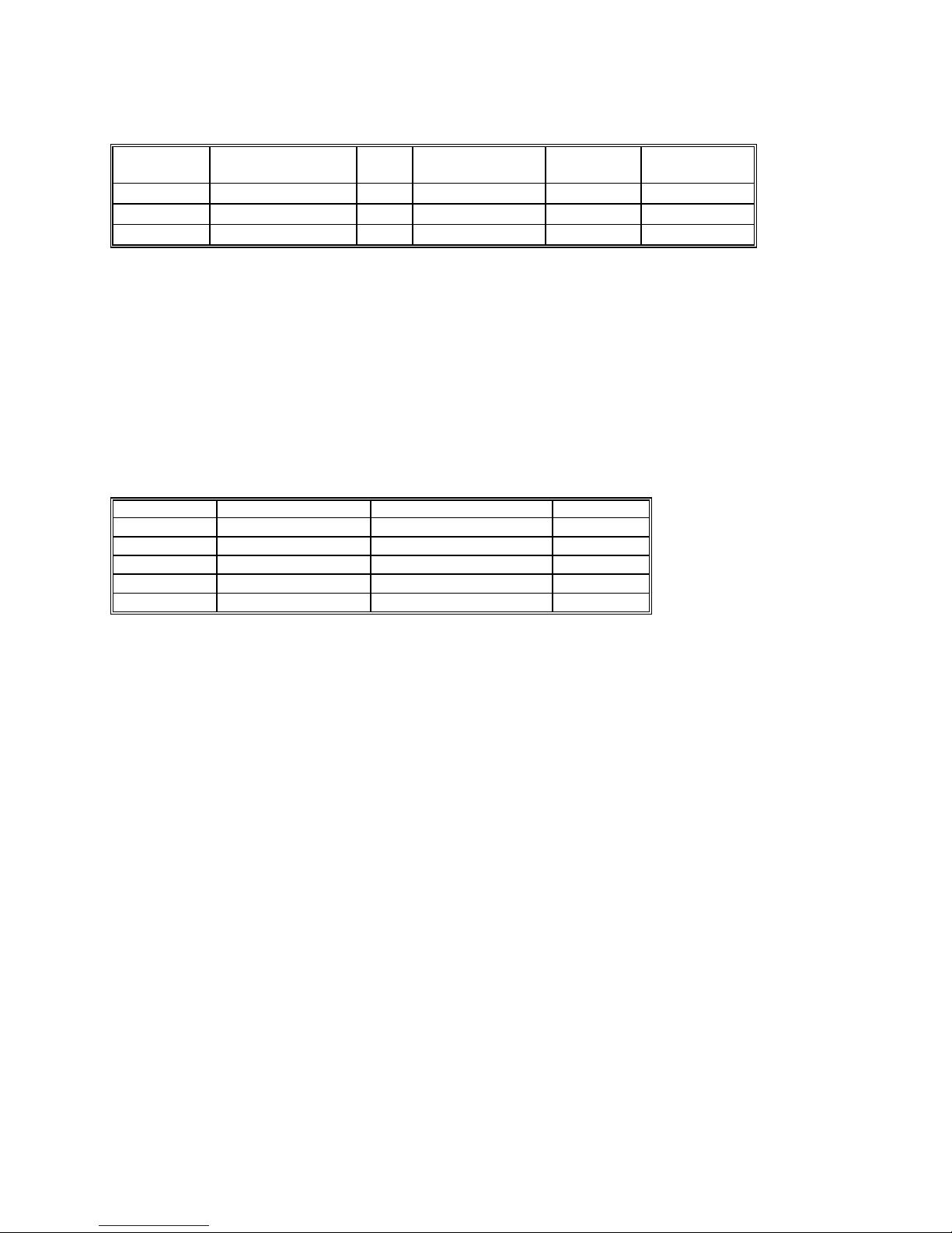
2.9.2 Capacitance, Ramp Method (SM2064)
Accuracy ± (% of reading + Farads) [1]

Signametrics 18
Range Full Scale
Reading
Resolution One Year
23°C ±5°C
1,200 pF 1,199.9 pF 0.1 pF 1.5 ± 0.25 pF
12 ηF 11.999 ηF 1 pF 1.2 ± 5 pF
120 ηF 119.99 ηF 10 pF 1.0
1.2 µF 1.1999 µF 100 pF 1.0
12 µF 11.999 µF 1 ηF 1.0
120 µF 119.99 µF 10 ηF 1.0
1.2 mF 1.1999 mF 100 ηF 1.2
12 mF 50.000 mF 1 µF 2
[1] Within one hour of zero, using Relative control. Accuracy is specified for values higher than 5% of the selected
range with the exception of the 1,200 pF range.
This Measurement is independent of set Aperture and Read Interval. If desired, the DMMSetCapsAveSamp()
function may be used to control measurement parameters. It is provided
means to fine tune the measurement timing for
the application, trading off accuracy for speed.
Measurement time will vary as function of the set parameters, selected range and measured capacitance. The following are
measurement times associated with the default parameters, as range is selected.
Range Input Measurement Time Measurement Rate (rps)
1,200 pF 5% of Scale
19.5 ms 51.3
1,200 pF Full Scale
52.3 ms 19.1
12 ηF 5% of Scale
70.0 ms 14.3
12 ηF Full Scale
118ms 8.5
120 ηF 5% of Scale
8.9 ms 112.4
120 ηF Full Scale
127 ms 7.9
1.2 µF 5% of Scale
15.6 ms 64.1
1.2 µF Full Scale
175 ms 5.7
12 µF 5% of Scale
14.1 ms 70.9
12 µF Full Scale
480 ms 2.1
120 µF 5% of Scale
17.3 ms 57.8
120 µF Full Scale
50.3 ms 19.9
1.2 mF 5% of Scale
52.6 ms 19.0
1.2 mF Full Scale
151.5 ms 6.6
12 mF 5% of Scale
52.8 ms 18.9
12 mF Full Scale
170 ms 5.9

19 Signametrics
2.9.3 Capacitance, In-Circuit Method (SM2064)
• Adjustable Peak Voltages Stimulus 100mV to 1.3V
• Minimum Parallel Load Resistance 100Ω
Accuracy ± (% of reading + Farads) [1]
Range Full Scale
3-½ Digits
Resolution One Year
23°C ±5°C [2]
24 ηF 23.99 ηF 10 pF 2.7 ± 100 pF
240 ηF 239.9 ηF 100 pF 2.5 ± 500 pF
2.4 µF 2.399 µF 1000 pF 2.5 ± 5 ηF
24 µF 23.99 µF 10 ηF
240 µF 239.9 µF 100 ηF
2.4 mF 2.399 mF 1 µF
24 mF 23.99 mF 10 µF
[1] Within one hour of zero, using Relative control, and Caps Open-Cal operation
[2] Accuracy is specified for values higher than 5% of the selected range with the exception of the 2.4
η
F range.
Capacitance Measurement time is independent of set Aperture and Read Interval. It depends on range, and
capacitance
.
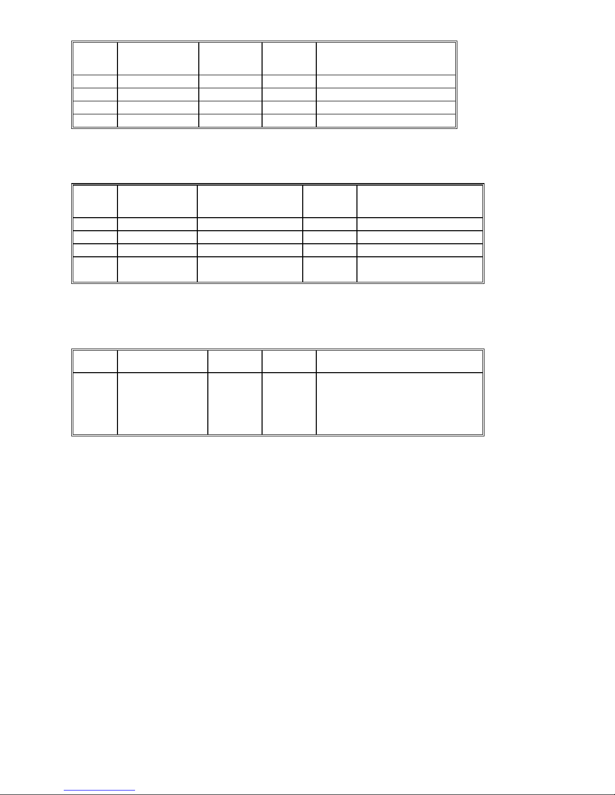
2.9.4 Inductance Measurement (SM2064)
Range Test frequency Full Scale
4 ½ Digits
Resolution Accuracy 23°C ±5°C
One Year [2]
24 µH 75 kHz 33.000 µH 1 ηH 3.0% + 500 ηH
240 µH 50 kHz 330.00 µH 10 ηH 2.0% + 3 µH
2.4 mH 4 kHz 3.3000 mH 100 ηH 1.5% + 25 µH
24 mH 1.5 kHz 33.000 mH 1 µH 1.5% + 200 µH
240 mH 1 kHz 330.00 mH 10 µH 2.5 + 3 mH
2.4 H 100 Hz 3.3000 H 100 µH 3 + 35 mH
[1] Within one hour of zero, and Open Terminal Calibration.
[2] Accuracy is specified for values greater than 5% of the selected range.
2.10 Time Measurements
2.10.1 Threshold DAC
• The Threshold DAC is used for selecting a detection level, providing optimal frequency and
timing measurements even at extreme duty cycle values.
± (% of setting + volts)
Selected VAC
range [1]
Threshold range (DC
level)
Threshold
DAC
resolution
Highest allowed input
Vp-p
Typical one year setting
uncertainty
240 mV -1.0 V to +1.0 V 0.5 mV 1.900 V 0.2% + 4 mV
2.4 V -10.0 V to +10.0 V 5.0 mV 19.00 V 0.2% + 40 mV
24 V -100.0 V to 100.0 V 50 mV 190.0 V 0.2% + 0.4 V
240 V -400 V to 400 V 500 V 850.0 V 0.2% + 4 V
[1] This table should be used in conjunction with the AC volts section above.

Signametrics 20
2.10.2 Frequency and Period Measurement
ACV Mode
•
Input Impedance 1 MΩwith < 300 pF
Frequency Range 2 Hz - 100 Hz 100 Hz-1 kHz 1 kHz-10 kHz 10 kHz-100 kHz 100 kHz-300 kHz
Resolution 1 mHz 10 mHz 100 mHz 1 Hz 1 Hz
Uncertainty is ±0.002% of
reading ± adder shown
4 mHz 20 mHz 200 mHz 2 Hz 5 Hz
Input Signal Range [1] 10% - 200%
of range
10% - 200%
of range
10% -200%
of range
10% - 200%
of range
45% -200%
of range
[
1] Input RMS voltage required for a valid reading. Do not exceed 250 V RMS input. For example, 10% -200%
of range indicates that in the 240 mVAC range, the input voltage should be 24 mV to 660 mV RMS.
ACI Mode
•
Input Impedance 10 Ωin the 3 mA and 30 mA ranges, 0.1 Ω in the 330 mA and 2.5 A ranges.
Frequency Range 2 Hz - 100 Hz 100 Hz-1 kHz 1 kHz-10 kHz 10 kHz-500 kHz
Resolution 1 mHz 10 mHz 100 mHz 1 Hz
Uncertainty 0.01% ±4 mHz 0.01% ±20 mHz 0.01% ±200 mHz 0.01% ±2 Hz
Input Signal Range,
2.4 mA, 240mA Ranges
[1]
10% -500%
of range
10% - 500%
of range
10% -500%
of range
10% - 500%
of range
Input Signal Range,
24 mA, 2.4 A ranges
50% -100%
of range
50% - 100%
of range
50% - 100%
of range
50% - 100%
of range
[1] Input current required to give a valid reading. For example, 10% -500% of range indicates that in the 3.3 mA
range, the input current should be 0.33 mA to 16.5 mA.
2.10.3 Duty Cycle Measurement
Frequency Range 2 Hz to 100 Hz 100 Hz to 1 kHz 1 kHz to 10 kHz 10 kHz to 100 kHz
Resolution 0.02% 0.2% 2% 20%
Typical Uncertainty is
±0.03% of reading ±
adder shown
0.03% 0.3% 3% 20%
Full scale reading 100.00 % 100.00 % 100.00 % 100.00 %
2.10.4 Pulse Width
± (% of reading + sec)
Polarity Frequency range Resolution Width range Typical
Uncertainty
Positive or negative pulse
widths
2 Hz to 100 kHz 1 µs 2 µs to 1 s 0.01 +/- 4 µs
This manual suits for next models
3
Table of contents
Other Signametrics Multimeter manuals


