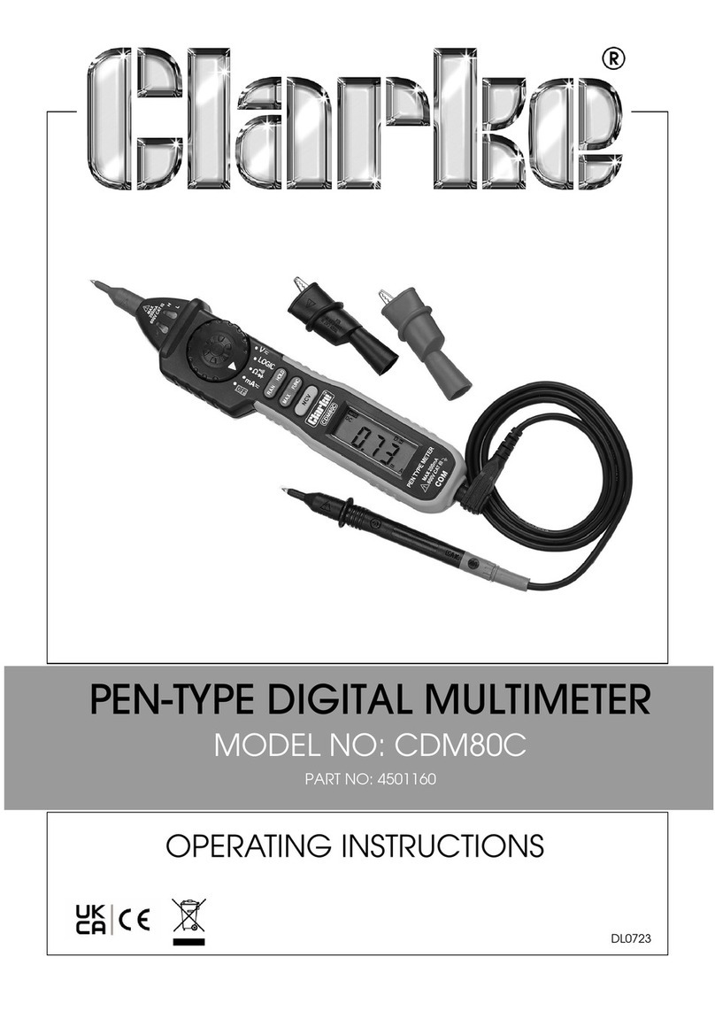
Clarke CDM80 User manual

CDM80 PEN PROBE DIGITAL MULTIMETER
OPERATING MANUAL
Model CDM80 / Part No:4500085

2
WARRANTY
Thank you for purchasing this CLARKE Digital Multimeter. Please read this manual thoroughly and
follow the instructions carefully. Before attempting to use the multimeter, thoroughly familiarise
yourself with this device & its operation. In doing so you will ensure the safety of yourself and
others around you, & can look forward to the multimeter giving you long and satisfactory service.
GUARANTEE
This product is guaranteed against faulty manufacture for a period of 12 months from the date of
purchase. Please keep your receipt which will be required as proof of purchase. This guarantee is
invalid if the product is found to have been abused or tampered with in any way, or not used for the
purpose for which it was intended. Faulty goods should be returned to their place of purchase, no
product can be returned to us without prior permission. This guarantee does not effect your
statutory rights.

3
READ ALL INSTRUCTIONS BEFORE OPERATING
SAVE THESE INSTRUCTIONS
Thank you for purchasing your Clarke CDM80 Pen Probe Digital Multimeter. Before attempting to
operate your new Multimeter please read these instructions thoroughly. You will need these
instructions for the safety warnings, precautions, assembly, operation, maintenance procedures,
parts list and diagrams. Keep your invoice with these instructions. Write the invoice number on the
inside of rear cover. Keep the instructions and invoice in a safe, dry place for future reference.
The warnings, cautions and instructions discussed in this instruction manual cannot cover all
possible conditions or situations that could occur. It must be understood by the operator that
common sense and caution are factors which cannot be built into this product, but must be
supplied by the operator.

4
TABLE OF CONTENTS
Warranty ............................................. 2
Safety Rules ....................................... 7
During Use.......................................... 8
Symbols ..............................................10
Preventive Maintenance .................... 12
Description ........................................ 13
Overview ............................................ 14
Specifications .................................... 18
Operation ........................................... 27
DataHold ................................. 27
Max Value Measuring & Hold 27
Switching Functions..................28
Switching Auto/Manual Range.. 28
Auto Power Off .......................29
Taking Measurements .......................30
Measuring DC Voltage ............30
Measuring AC Voltage.............34
Measuring Resistance.............37
Diode Testing .........................40
Continuity Testing ...................43
Measuring DC Current ...........44
Measuring AC Current.............46
Logic Test ...............................48
Maintenance ......................................50
Battery Replacement ..............50
Test Lead Replacement ..........52
Accessories .......................................53

5
WARNING:- BE EXTREMELY CAREFUL IN THE USE OF THIS METER. Improper use
of this device can result in electric shock to the user or destroy the meter. Follow
all safety rules in this manual and the normal safety precautions used in working
with electrical circuits. Do not service this device if you are not qualified to do so.
All repairs should be performed by an authorised Clarke repair facility. To ensure
safe operaton, and in order to achieve the full functionality of the meter, follow the
directions in this manual carefully.

6
This meter has been designed according to IEC1010 concerning electronic measuring instruments
with an overvoltage category CAT III 600V and pollution 2.
Follow all safety and operating instructions to make sure that the meter is used safely and is
kept in good operating condition.
With proper use and care, the digital meter will give you years of excellent service.
Measurement category III is for measurements performed in building installation. (Examples are
measurements on distribution boards, circuit breakers, wiring including cables, busbars, junction
boxes, switches, socket outlets (fixed installation), equipment for industrial use and some other
equipment; for example, stationary motors with permanent connection to the fixed installation).

7
SAFETY RULES
1. When using the meter observe all normal safety rules concerning:
• protection against the dangers of electrical current.
• protection of the meter against mis-use.
2. Before using the meter, inspect it carefully to make sure that it has not been damaged during
shipping.
3. The test lead or test clip must be in good condition. Before using, verify that the insulation on
test lead or test clip is not damaged and/or the lead wires are not exposed.
4. Full compliance with safety standards can be guaranteed only if used with test leads supplied.
Use ONLY authorised Clarke replacement parts.
5. Always make sure the correct function and range are selected for your job.
6. Never exceed the limit values (listed in SPECIFICATIONS Section of this manual) for each
range of measurement.

8
7. When the meter is linked to a circuit, do not touch the probe tip of the meter or the test lead/
test clip.
8. In Manual Mode, when the value scale to be measured is unknown beforehand, select the
highest range.
9. Do not use this tool to measure voltage higher than 600V above earth ground.
10. Always be careful when working with voltages above 60V DC or 30V AC rms. Always keep
fingers behind the probe barrier while measuring.
11. Never connect the meter leads across a voltage source while the Mode Selector is in the
resistance, diode, or continuity mode. Doing so can damage the meter.
12. Never perform resistance, diode, or continuity measurements on live circuits.
13. Before rotating the Mode Selector to change the function, disconnect the probe tip of meter
and the probe of the test lead (or test clip) from the circuit being tested.
14. Never use the meter near explosive air, steam, or dirt.

9
15. If any faults are observed, STOP using and have the meter serviced by a qualified technician
immediately.
16. Never use the meter unless the outer casing is in place and fully fastened.
17. Do not store or use meter in areas exposed to direct sunlight, high temperature, humidity, or
condensation.

10
SYMBOLS Important safety information
Double insulation (Protection class II)
CAT III Overvoltage (Installation) category III, Pollution Degree 2 per IEC10101 refers to
the level of Impulse Withstand Voltage protection provided.
Conforms to European union directive
Earth ground
AC Alternating current
DC Direct current

11
AC or DC (alternating current or direct current)
Diode
Continuity buzzer
M.H The maximum value is being held.
DH This indicates that the display data is being held.
AUTO Auto range
- + Low battery

12
PREVENTIVE MAINTENANCE
1. Do not attempt to adjust or repair the meter by removing the rear case while voltage is being
applied. Only a qualified technician should attempt repairs on this meter.
2. Before opening the battery cover or case of the meter, always disconnect the probe tip of the
meter and the probe of the test lead (or test clip) from all tested circuits.
3. To avoid the wrong reading, when the meter displays “ - + ”, the battery power is low and the
battery should be changed immediately.
4. Do not use abrasives or solvent to clean the meter. Use only a damp cloth and mild detergent.
5. Always set the Mode Selector to the OFF position when the meter is not in use.
6. If the meter is to be stored for a long period of time, the batteries should be removed to
prevent damage to the unit.

13
DESCRIPTION
This meter is a portable professional measuring instrument with easy to read LCD display and
convenient carrying case.
Multi-function Mode selector makes measurement convenient. Includes overload protection and
low battery indicator. This meter is ideal for use in the field, workshop, school, hobby, and home
applications.
Your CDM80 features:
- Auto Range and Manual Range function
- Auto Power Off
- Data Hold and Maximum Value Measure & Hold
- Range Display with unit enunciators measuring results

14
OVERVIEW
1. Probe
2. Rotating Probe Socket
3. LED Indicator
4. Probe Barrier
5. Mode Selector
6. DATAHOLD Button
7. RANGE Button
8. MAX.HOLD Button
9. FUNC. Button
10. Panel
11. LCD Dispay
12. COM Jack

15
nottuB edoM demrofrepnoitarepO
H-ATADnoitisophctiwsynA noitpOpu-rewoP .ataddlohotdesusinottubsihT .erutaefffo-rewopcit
amotuaselbasiD
EGNAR ,V ΩΩ
Ω
ΩΩ Amdna .egnaRlaunaM&egnaRotuAneewtebsehctiwS
H.XAMnoitisophctiwsynA .eulavmumixa
mehtdlohdnaerusaemotdesU
.CNUF VcigoL
ΩΩ
Ω
ΩΩ
Am
egatlovCAdnaCDneewtebsehctiwS .gnitsetcigoLrofnwoddlehebtsuM tseTedoiD,tnemerusaemecnatsiseRneewtebsehctiwS .kcehcytiunitnoCdna .tnerrucCAdnaCDneewtebsehctiwS

16
Probe
Input terminals for V, mA, Ω./ / and logic test.
Rotating Probe Socket
Rotates the probe in or out of the meter.
LED Indicator
Indicates high level and Low level at Logic test range.
Probe Barrier
Helps to keep hands away from the probe.
Mode Selector
This switch is used to select functions and desired ranges.
LCD Display
Displays the measurement information.
COM Jack
Terminal for Test Probe/Test Clip.

17
SPECIFICATIONS
Accuracy is specified for a period of one year after calibration at 64 F to 82 F (18 C to 28C).
Circumstance Temperature: 23±5°C Relative Humidity: < 75%.
GENERALSPECIFICATIONS
Environment conditions:
600V CAT. III
Pollution degree: 2
Altitude < 2000m
Operating temperature: 32°F~122°F (0~40°C) (<80% RH, <10°C non-condensing)
Storage temperature: 14°F ~122°F (10~50°C) (<70% RH, battery removed)

18
Max. voltage between terminals and earth ground: 600V DC or AC.
Auto ranges and manual range.
Display: 20mm LCD.
Max. Show Value: 1999 (3 1/2).
Polarity Indication: ‘-’ indicates negative polarity.
Range Overload Indication: Display ‘OL’.
Sampling Time: approx. 0.4 second.
Display: Function and electrical capacity.
Low Battery Indicator: ‘ - + ’ displayed.
Auto power off time: 15 min.
Power Supply: 2 x 1.5V AAA batteries.
Dimensions (L x W x H): 208 x 38 x 29
Weight: approx. 0.21kg. (including battery)

19
DC VOLTAGE
Input Impedance:10MΩ
Overload Protection: 200mV range: 250V DC or AC rms,
2V600V ranges: DC 600V or AC 600V rms.
Max. Input Voltage: 600V DC
egnaR noituloseR ycaruccA
Vm002Vm1.0
V2V100.0
V02V10.0)stigid2+gdrfo%7.0(±
V002V1.0
V006V1

20
AC VOLTAGE
Input Impedance:10MΩ.
Overload Protection:200mV range:250V DC or AC rms/2V600V ranges:DC 600V or AC 600V rms
Frequency Range: 40 to 400Hz
Response: Average, calibrated in rms of sine wave.
Max. Input Voltage: 600V rms AC
egnaR noitloseR ycaruccA
Vm002Vm1.0
V2V100.0
V02V10.0)stigid3+gdrfo%8.0(±
V002V1.0
V006V1)stigid3+gdrfo%0.1(±
Table of contents
Other Clarke Multimeter manuals

Clarke
Clarke CDM-35 User manual

Clarke
Clarke CDM10A User manual

Clarke
Clarke CDM3 User manual

Clarke
Clarke CDM 10 User manual
Clarke
Clarke CDM80C User manual

Clarke
Clarke CDM20 User manual

Clarke
Clarke CDM 85 User manual
Clarke
Clarke CDM-45 User manual

Clarke
Clarke CDM 85 Operating instructions

Clarke
Clarke CDM 15 User manual