manuals.online logo
Brands
  1. Home
  2. •
  3. Brands
  4. •
  5. 3B SCIENTIFIC PHYSICS
  6. •
  7. Multimeter
  8. •
  9. 3B SCIENTIFIC PHYSICS Escola 10 User manual

3B SCIENTIFIC PHYSICS Escola 10 User manual

3B SCIENTIFIC® PHYSICS
1
Multimeter Escola 10 1006810
Instruction sheet
11/14 SD/UD
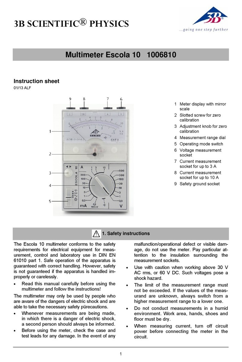
1 Meter display with mirror
scale
2 Slotted screw for zero
calibration
3 Adjustment knob for zero
calibration
4 Measurement range dial
5 Operating mode switch
6 Voltage measurement
socket
7 Current measurement
socket for up to 3 A
8 Current measurement
socket for up to 10 A
9 Safety ground socket
1. Safety instructions/using the equipment safely
The Escola 10 multimeter is designed to display
electrical measurements in the ranges and
measurement environments specified in its tech-
nical data.
It conforms to safety regulations for electrical
measurement, control and laboratory equip-
ment, as specified in DIN EN 61010-1, protec-
tion class 2 and to excess voltage category CAT I
for up to 600 V. It is intended for measurements
on experiments and laboratory apparatus. It is
not approved for measurements on low-voltage
distribution equipment, such as sockets, fuses,
etc.
CAT I: Signal layer, telecommunications, elec-
tronic equipment with only minor excess voltage
transients
CAT II: Domestic appliances, mains sockets,
portable instruments etc.
CAT III: Supply via buried cabling, built-in swit-
ches, automatic circuit breakers, sockets or
contactors
CAT IV: Equipment and installations supplied,
for example, by overhead mains cables and
therefore subject to greater risk of lightning
strikes. This includes, for example, main
switches at the building mains feed, electricity
meters and ripple control receivers.
Safe operation of the multimeter is guaranteed if
it is solely used as specified. Safety cannot be
guaranteed, however, if the multimeter is used
incorrectly or handled without due care and at-
tention. In order to avoid serious injury due to
current or voltage shocks, the following safety
instructions are to be observed at all times:
2
•
Carefully read the instruction manual before
using the multimeter and obey the instruc-
tions therein.
•
The multimeter may only be used by per-
sons who are able to recognise the risks of
contact and take due precautions to avoid
them.
This multimeter is not a toy and must not fall into
the hands of children.
•
Do not place it, keep it or use it anywhere
within reach of children.
•
When the multimeter is used by teenagers,
trainees etc., a suitable person should su-
pervise to ensure the equipment is used
safely.
•
If measurements are made where there are
any risks of coming into contact with electric-
ity, a second person is to be informed.
The assumption needs to be made that unfore-
seen voltages may be present in the vicinity of
objects being measured (e.g. faulty equipment
or capacitors).
•
Before using the multimeter, check the
housing and measuring leads for damage
and if there should be any malfunctions or
visible damage, the multimeter is not to be
used. Pay specific attention to the insulation
for the measuring sockets.
•
Be particularly careful when measuring volt-
ages in excess of 33 V AC (RMS) or 70 V
DC.
•
For voltages which are in excess of 33 V AC
or 70 V DC, only use safety measurement
leads conforming at least to CAT II.
•
The authorised measuring range is not to be
exceeded. If measurements are made when
the magnitude of the variable is unknown,
always select a large measuring range be-
fore shifting down to lower ones.
•
The multimeter may not be used to make
measurement on circuits which exhibit co-
rona discharge (high voltage).
•
Particular care is to be taken when making
measurements on high-frequency circuits
where dangerous voltages may arise due to
superimposition of components.
•
Make very sure that the voltage value be-
tween the measured contact and earth or
between the ground socket and the meas-
urement socket does not exceed 1000 V.
•
In order to check that the multimeter is ready
to use, select the battery test function. Af-
terwards, it is then possible to check that the
voltage source is disconnected and no volt-
age is present.
•
The multimeter may only be used in a dry,
dust-free environment with no risk of explo-
sions occurring.
•
When measuring current in a circuit, make
sure to switch off the power before connect-
ing the multimeter into the circuit.
•
When making measurements, always con-
nect the ground lead first. Disconnect the sig-
nal measurement lead before unplugging the
ground.
•
Turn off the multimeter before opening the
casing, disconnect the power to the circuit
and the measuring leads from the multime-
ter.
2. Symbol legend
Hazard, read instruction sheet
V
Voltage
A
Current
Moving coil galvanometer
Apparatus with electronic amplifier
DC quantities accuracy class 2
AC quantities accuracy class 3
Use in horizontal position
Use in vertical position
DC quantities
AC quantities
Needle position zero centre
“OFF” position
Measuring category as per IEC EN
61010-1
Double insulated casing
CE EU conformity mark
Earth symbol
┴
Ground symbol
Battery symbol
3. Technical data
Dimensions: 98 x 148 x 49 mm approx.
Weight: 300 g approx.
Scale length: 80 mm
Pointer deflection 0…90°
3
Operating alignment: Vertical/horizontal
Power supply: 1x 1.5 V, AA IEC LR6
Connectors: 4-mm safety sockets
Voltage ranges: 0.1, 0.3, 1, 3, 10, 30,
100, 300, 600 V AC/DC
Current ranges: 0.1, 0.3, 1, 3, 10, 30,
100, 300 mA; 1, 3, 10 A
AC/DC
Input resistance: 1 MΩAC/DC
Voltage drop when
measuring current: 100 mV approx. AC/DC
Accuracy: DC class 2, AC class 3
Electrical
zero-point offset: in all DC ranges
Accuracy with
zero-point offset: Class 5
Frequency ranges:
1 V – 600 V: 20 Hz…50 Hz…20 kHz
0.3 V: 20 Hz…50 Hz…9 kHz
Current ranges: 20 Hz…50 Hz…43 kHz
Signal form: Sine (1% max. discrep-
ancy)
Peak factor:
2
Overload protection
Voltage: 600 V long-term in all
voltage ranges
Current ranges:
Current limit integral: 450 A
2
s
Transient limitI
FMS
: 300 A
Long-term current
limitI
FAV
: 20 A
Ambient temperature: 5°C...23°C…40°C
Storage temperature: -20…70°C
Relative humidity: < 85% with no conden-
sation
Shock tests: max. 147 m/s²
Electrical safety:
Safety specifications: EN 61010-1
Excess voltage
category: CAT I: 600 V
Contamination level: 2
Protection type: IP20
Electromagnetic compatibility:
Interference emission: EN 55011:2009
Interference resistance: EN 61326-1:2013
4. Description
The Escola 10 multimeter enables precision
measurements by analogue means in education,
training and practical applications. It measures
AC and DC voltage or current and provides for
measurements with the needle centred on the
dial for DC quantities. Resistance (R) and con-
ductance (G) or impedance (Z) and admittance
(Y) can be obtained by division.
All measurement ranges are selected by means of
the measurement range dial. Two linearised mirror
scales, graded in a 1:3 ratio, guarantee easy read-
ability of the measured values.
The equipment is turned on by means of the
operating mode switch, which is also used to
select between AC, DC or centre zero-point.
The trimmer for setting the zero point in the
centre allows the zero point to be set precisely
when it drifts electrically.
Isolation of the sockets for voltage and current
measurement allow both to be measured in
succession simply by turning the range selector
switch, without any need for reconnecting or
changing the measuring leads.
Use of a robust core-magnet measuring instrument
set-up and an impact resistant casing allows the
instrument to withstand rough handling in awkward
conditions.
The Escola 10 is protected in such a way that
overloads in the selectable current ranges
automatically cause the power to be limited.
5. Operation
•
Switch the multimeter on by select the de-
sired operating mode, , or .
•
To turn off the multimeter, set the mode
switch to the off position .
•
To test the battery, disconnect all leads from
the multimeter, set the operating mode
switch to and the measuring range
switch to . In the range, the
needle should deflect all the way to the end.
If this is not the case, the battery must be
replaced immediately.
4
5.1 Current measurement
The nominal voltage of the voltage
source may not exceed 600 V. Do not
make measurements in the low-voltage
mains region.
The multimeter is to be connected in series with
the load on the side where the voltage with re-
spect to ground is lowest.
•
Before making any current measurements, set
the mode switch to or as appropri-
ate.
•
Connect the terminal at the lower potential
to the earth socket.
•
Currents of less than 3 A can be measured
between the earth socket and measuring
socket "A".
•
Currents of less than 3 A can be measured
between the earth socket and measuring
socket "A". Currents higher than 3 A should
be measured between the earth socket and
measuring socket "10A".
•
Set the switch to
A
mode and select the
desired measuring range. lf the current to be
measured is unknown beforehand, set the
measurement range dial to the highest
range and work down.
The fact that measurements can be made with-
out disconnecting the instrument and using
overload protection without fuses means that
converters may also be connected into the cir-
cuit.
V
A
10A
Fig. 1 Current measurement
5.2 Voltage measurement
The nominal voltage of the voltage
source may not exceed 600 V. Do not
make measurements in the low-voltage
mains region.
•
Before making any voltage measurements, set
the mode switch to or as appropri-
ate.
•
Use the "V" socket on the right for voltage
measurements.
•
Set the switch to
V
mode and select the
desired measuring range. lf the voltage to be
measured is unknown beforehand, set the
measurement range dial to the highest
range and work down. The 100 mV voltage
range is associated with a current range of
0.1 mA.
V
A
10A
Fig. 2 Voltage measurement
5.3 Measuring current and voltage without
reconnecting
Isolated current and voltage sockets allow
measurements of both current and voltage to be
made in sequence without disconnecting the
measuring leads. That means that in both AC
and DC modes, resistance, conductance, im-
pedance and admittance can all be calculated
forming the appropriate quotients.
V
A
10A
Fig. 3 Simultaneous current and voltage measure-
ment
5.4 Resistance and conductance
According to the defining equation for a linear
resistance, R= V/I, or conductance G = I/V, the
Escola 10 can be connected in circuit as in Fig.
3 so that current and voltage can be measured
one after the other, allowing for resistance
measurements to be made over a range from
mΩup to several MΩ.
Therefore conductances in a range from under 1
µS up to 30 S can be measured by taking the
reciprocal of the resistance.
One very key advantage of the Escola 10 is that
the instrument, when connected as in Fig. 3, can
measure both current and voltage ranges with-
out having to disconnect it.
5
5.5 Impedance and admittance
If the circuit in Fig. 3 is powered by a sinusoidal
AC voltage source instead of a DC source, us-
ing the definitions for impedance Z= V/Iand
admittance Y= I/Vmeans that AC measure-
ments can also be measured in a variety of
ranges in a similar way to the DC quantities in
5.4.
The Escola 10 is particularly useful in this re-
spect because it allows for measurements to be
made not only at 50 Hz, but right across the low-
frequency range.
5.6 Measurements with the zero point of the
needle centred
This kind of measurement can only be made in
DC ranges.
•
To make a measurement with the zero point
in the centre, push the mode switch to .
•
Before measuring the external quantity,
calibrate the zero point using the trimmer to
set the point in the direct centre of the scale.
The full extent of the measuring remains avail-
able so there is no separate labelling for the
range selector switch.
For a range 0 V ... 10 V, for example, the limits
now become -5 V ... 0 V ... +5 V absolute or 0 V
... ±5 V. Positive values of voltage at the V
socket or current at the A socket cause the nee-
dle to move to the right while negative values
cause it to move to the left. The scales are la-
belled accordingly (smaller auxiliary numbering).
5.7 Calibrating zero-point
•
Turn on the multimeter, set the maximum
voltage range of 600 V and connect the
ground socket to the voltage socket using a
short lead.
•
Set up the multimeter in a horizontal position
and correct the zero-point of the dial with the
help of the adjustment knob.
5.8 Switching off
•
Always set the measuring mode to after
completion of measurements to avoid un-
necessary use of the battery.
6. Maintenance
6.1 Changing the battery
All measuring leads must be discon-
nected from the multimeter before the
casing is opened.
•
From time to time, check the state of the
battery (see 5. Operation).
Remove discharged or corroded batter-
ies from the multimeter.
During prolonged periods of disuse,
also remove the battery from the mul-
timeter.
•
Unscrew the back of the casing.
•
Replace flat batteries with 1.5-V alkaline
batteries of size AA IEC LR6.
•
Place the negative pole of the battery on the
spring.
The polarity is also marked on the board with
plus and minus symbols. Additionally, a me-
chanical clip on the positive side prevents bat-
tery contact when polarity is reversed.
•
Close casing again.
Fig. 4 Changing the battery
•
Do not dispose of the
battery in regular
household refuse. Fol-
low the local regula-
tions (In Germany:
BattG; EU:
2006/66/EG).
3B Scientific GmbH ▪Rudorffweg 8 ▪21031 Hamburg ▪Germany ▪www.3bscientific.com
Subject to technical amendments
© Copyright 2014 3B Scientific GmbH
6.2 Cleaning
•
For cleaning, use a soft cloth, slightly mois-
tened with alcohol, or a brush.
•
In order to remove a potential electrostatic
charge from the meter display window,
which can easily influence measurements,
follow the instructions above.
Dirt or moisture in the measurement sockets can
affect readings.
•
Shake out any dirt that may be in the meas-
urement sockets.
•
Soak a new swab with isopropyl alcohol and
work around the inside of each measure-
ment socket.
7. Disposal
•The packaging should be disposed of at
local recycling points.
•Should you need to
dispose of the equip-
ment itself, never
throw it away in normal
domestic waste. Local
regulations for the dis-
posal of electrical
equipment will apply.
•Do not dispose of the battery in regular
household refuse. Follow the local regula-
tions (In Germany: BattG; EU: 2006/66/EG).

Other 3B SCIENTIFIC PHYSICS Multimeter manuals

3B SCIENTIFIC PHYSICS DT9201A User manual

3B SCIENTIFIC PHYSICS

3B SCIENTIFIC PHYSICS DT9201A User manual

3B SCIENTIFIC PHYSICS 1018832 User manual

3B SCIENTIFIC PHYSICS

3B SCIENTIFIC PHYSICS 1018832 User manual

3B SCIENTIFIC PHYSICS Escola 2 User manual

3B SCIENTIFIC PHYSICS

3B SCIENTIFIC PHYSICS Escola 2 User manual

3B SCIENTIFIC PHYSICS Escola 10 1006810 User manual

3B SCIENTIFIC PHYSICS

3B SCIENTIFIC PHYSICS Escola 10 1006810 User manual

3B SCIENTIFIC PHYSICS Escola 30 User manual

3B SCIENTIFIC PHYSICS

3B SCIENTIFIC PHYSICS Escola 30 User manual

3B SCIENTIFIC PHYSICS U17450 User manual

3B SCIENTIFIC PHYSICS

3B SCIENTIFIC PHYSICS U17450 User manual

3B SCIENTIFIC PHYSICS E 1018832 User manual

3B SCIENTIFIC PHYSICS

3B SCIENTIFIC PHYSICS E 1018832 User manual

3B SCIENTIFIC PHYSICS 100 User manual

3B SCIENTIFIC PHYSICS

3B SCIENTIFIC PHYSICS 100 User manual

3B SCIENTIFIC PHYSICS Escola 10 User manual

3B SCIENTIFIC PHYSICS

3B SCIENTIFIC PHYSICS Escola 10 User manual

3B SCIENTIFIC PHYSICS U17451 User manual

3B SCIENTIFIC PHYSICS

3B SCIENTIFIC PHYSICS U17451 User manual

3B SCIENTIFIC PHYSICS E 1006809 User manual

3B SCIENTIFIC PHYSICS

3B SCIENTIFIC PHYSICS E 1006809 User manual

3B SCIENTIFIC PHYSICS Escola 30 User manual

3B SCIENTIFIC PHYSICS

3B SCIENTIFIC PHYSICS Escola 30 User manual

3B SCIENTIFIC PHYSICS Escola 2 1006811 User manual

3B SCIENTIFIC PHYSICS

3B SCIENTIFIC PHYSICS Escola 2 1006811 User manual

3B SCIENTIFIC PHYSICS 1017895 User manual

3B SCIENTIFIC PHYSICS

3B SCIENTIFIC PHYSICS 1017895 User manual

3B SCIENTIFIC PHYSICS E 1018832 User manual

3B SCIENTIFIC PHYSICS

3B SCIENTIFIC PHYSICS E 1018832 User manual

3B SCIENTIFIC PHYSICS AM51 User manual

3B SCIENTIFIC PHYSICS

3B SCIENTIFIC PHYSICS AM51 User manual

Popular Multimeter manuals by other brands

Tektronix DMM4040 user manual

Tektronix

Tektronix DMM4040 user manual

Picotest M3510A user manual

Picotest

Picotest M3510A user manual

Clarke CDM80 operating manual

Clarke

Clarke CDM80 operating manual

YOKOGAWA 734 01 user manual

YOKOGAWA

YOKOGAWA 734 01 user manual

Pyle PDMT29 manual

Pyle

Pyle PDMT29 manual

Aktacom ??-1142 user manual

Aktacom

Aktacom ??-1142 user manual

Duratool D03143 quick start guide

Duratool

Duratool D03143 quick start guide

Fluke 175 Supplement manual

Fluke

Fluke 175 Supplement manual

Fluke 110 user manual

Fluke

Fluke 110 user manual

hc-cargo DT-6920 user manual

hc-cargo

hc-cargo DT-6920 user manual

Klein Tools MM2000 instruction manual

Klein Tools

Klein Tools MM2000 instruction manual

Monacor MT-300 instruction manual

Monacor

Monacor MT-300 instruction manual

Amprobe DM9C user manual

Amprobe

Amprobe DM9C user manual

Neoteck 8233D Pro manual

Neoteck

Neoteck 8233D Pro manual

PANCONTROL PAN 186 manual

PANCONTROL

PANCONTROL PAN 186 manual

Steren MUL-105 user manual

Steren

Steren MUL-105 user manual

Elma Instruments 6700 user manual

Elma Instruments

Elma Instruments 6700 user manual

Philips PM2517E Service manual

Philips

Philips PM2517E Service manual

manuals.online logo
manuals.online logoBrands
  • About & Mission
  • Contact us
  • Privacy Policy
  • Terms and Conditions

Copyright 2025 Manuals.Online. All Rights Reserved.