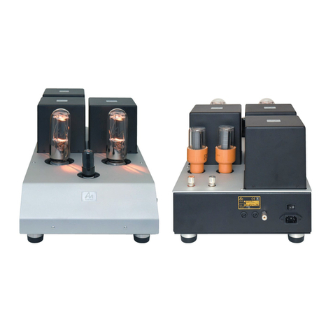
Signature Origin Signature Century User manual

Home of Signature Quality
Signature Origin
Signature Century – Manual.
Ultra-high resolution stereo power amplifier
by Frans de Wit.
Congratulations on purchasing this extremely capable; exquisitely built state-of-the-art
stereo power amplifier. You will have countless hours of enjoyment from this exceptional
device. The operating manual is designed to be as simple as possible so that you can start to
enjoy this revolution in music with minimal delay.
1) Audio (line level) XLR or RCA input left.
2) Audio (line level) XLR or RCA input right.
3) N0X (Non-zero-crossing) socket left.
4) N0X (Non-zero-crossing) socket right.
5) Soft-clipper on/off switch left.
6) Soft-clipper on/off switch right.
7) Mundorf binding-post red (positive signal) left.
8) Mundorf binding-post red (positive signal) right.
9) Mundorf binding-post black (positive signal) left.
10) Mundorf binding-post black (positive signal) right.
11) Mains fuse for amplifier left.
12) Mains fuse for amplifier right.
13) Mains fuse for front panel lighting.
14) Mains fuse for mains on/off controller and protection.
15) Mains switch.
16) Trigger (remote) connector.
17) Mains socket C13, C19 or PowerCON.
18) Amplifier level indicator left.
19) Amplifier level indicator right.
20) Amplifier power supply status left [3 lights].
21) Amplifier power supply status right [3 lights].
22) Mains on/off controller status lights [4 lights].
23) Front panel lighting control key.
24) Front panel lighting controls [4 controls] red, green, blue and amber.
25) Finally.

Home of Signature Quality
Signature Origin
Amplifier backside.
Amplifier front side.
Amplifier top side.

Home of Signature Quality
Signature Origin
Amplifier backside.
Amplifier front side.
Amplifier top side.

Home of Signature Quality
Signature Origin
Connecting and controlling your Signature Century amplifier:
1) 2)
Audio (line level) XLR or RCA input left/right.
The amplifier may be equipped with either XLR or RCA input connectors. This is determined
at the time the amplifier is ordered. Later, if required, the amplifier can be re-equipped:
XLR can be changed to RCA; or RCA can be changed to XLR.
3) 4) N0X (Non-zero-crossing) socket left/right.
All two-wire loudspeaker cables can be used to connect the amplifier to the loudspeaker.
The amplifier can also use cables that have a RF (radio frequency) shield, in which case the
shield SHOULD be connected to the N0X output using a 4mm banana plug. TAKE CARE:
Because the N0X output has an offset, voltage, equal to the power supply voltage of the
amplifier, the loudspeaker cable shield MUST NOT be connected (in any way) to any other
point of the amplifier or the loudspeaker system.
5) 6) Soft-clipper on/off switch left/right.
The ultra-balanced input circuit of the amplifier is equipped with a soft-clipper function.
Using these push-button switches, this function can be enabled or disabled. When the
function is enabled, the button will be illuminated in RED.

Home of Signature Quality
Signature Origin
W1) 100Wrms @ 8ohm output power reached at 2Vrms input clipper off.
V1) 2.0Vrms input signal.
V2) 4.3Vrms input signal.
B1) Output power soft-clipper off.
B2) Output power soft-clipper on.
R1) Ultra-balanced-input-amplifier output voltage clipper off.
R2) Ultra-balanced-input-amplifier output voltage clipper on.
G1) Input voltage.
From the graph can be read the following:
Normally, soft-clipper off, the amplifier delivers 100Wrms in 8ohm at 2Vrms input
signal [lines W1 and B1 cross].
With the soft-clipper function switched on, the amplifier delivers 100Wrms in 8ohm
at 4.3Vrms input signal [lines W1 and B2 cross].
Normally, soft-clipper off, the amplifier [hard] clips at an input voltage of 2.25Vrms
With the soft-clipper function switched on, amplifier [hard] clipping is delayed until
an input signal of (near to) 11Vrms
The absolute maximum output power, in 8ohm, of the amplifier is, depending on
many factors, 125Wrms.
The line R1 shows the maximum output voltage of the hyper-balanced input-stage, it
can be seen that this input-stage [hard] clips at (near to) 10Vrms, the hyper-balanced
input-stage will never clip if the soft-clipper is switched on.
7) 8) 9) 10) Mundorf binding-post’s, red (left/right)/black (/left/right).
Loudspeakers are connected to the amplifier using these high quality binding-post’s that are
custom-made by Mundorf for the Signature Century amplifier. The binding-posts can
accommodate the bare cable-ends, 4mm banana plugs and cable-forks. As mentioned
before, shielded cables can also be accommodated.
11) 12) Mains fuse for amplifier left/right.
The top most mains fuses are used to protect the amplifier power supply, for the 220~240V
mains amplifier this will be 4A fuses, for the 110~120V model these will be 8A fuses.

Home of Signature Quality
Signature Origin
13) Mains fuse for front panel lighting.
This fuse protects the front-panel lighting power supply, for the 220~240V mains amplifier
this will be 1A fuses, for the 110~120V model these will be 2A fuses.
14) Mains fuse for mains on/off controller and protection.
This fuse protects the mains power on/off controller, for the 220~240V mains amplifier this
will be 500mA fuses, for the 110~120V model these will be 1A fuses.
About all mains fuses.
All mains fuses are of a ‘Push to Reset’ type produced by TE-Connectivity as shown in the
photo below:
If the fuse is activated, e.g. protects against some fault, it will show a (extra bright) white flag (the
fuse shown on the right hand side of the above picture). To reset the fuse use the following
procedure:
Switch OFF all audio devices in the system using their individual mains switches
Switch the amplifier OFF (using the mains switch [15])
Reset the fuse; press the fuse until it clicks in to the closed position.
Switch the amplifier ON (using the mains switch [15])
Switch all other audio devices ON.
If this reoccurs then contact your dealer.
Note that the fuses cannot be manually released (switched off), always use the mains switch if you
need to switch the amplifier off

Home of Signature Quality
Signature Origin
15) Mains switch.
Rocker-switch to switch the amplifier on or off, when in the on position the switch will be lit
red. If the switch is in the on position and the switch is not lit, then check the power cord
and its connection to the mains outlet. For the amplifier to switch fully on, the trigger
(remote) must be on, or the dummy trigger plug (delivered with the amplifier) must be in
place. If the amplifier is connected to a remote controller (e.g. the trigger input is connected
to a device with a trigger output) and it will not switch on, then remove the trigger cable
and place the dummy trigger plug, if the amplifier does not switch on then check the remote
controller and the trigger cable, when in doubt contact your dealer.
16) Trigger (remote) connector.
The amplifier is delivered including a dummy trigger plug, when this plug is in place the
mains switch will operate the amplifier (switching it on and off).
Your current system may be fitted with a trigger
(wired remote control) function than can be used to
switch your amplifier on and off together with the
remainder of your system. While not all trigger
systems on the marked are equal, you will need a
trigger cable that is dedicated for the type of remote
controller, contact your dealer he will supply a fitting
cable. If no fitting ‘standard’ cable is available then Signature Origin will create a cable and
converter for your system, to be able to do this Signature Origin may need technical
information about your system, contact your dealer if needed.
17) Mains socket C13, C19 or PowerCON.
The amplifier is fitted with a mains socket, when the amplifier is ordered it is possible to
select one of these three sockets C13, C19 or PowerCON.
Signature Origin
advices to select
either the C19 or
PowerCON socket,
we advise against
using the C13
socket (but it may be needed to use this socket for compatibility reasons).

Home of Signature Quality
Signature Origin
18) 19) Amplifier level indicator left/right.
The front panel of the amplifier contains two VU-meter devices, these measurement
instruments are intended to give the user information about the power that is delivered to
the loudspeakers. The range of these instruments is 0 to 100%, where 100% (needle to the
far right of the VU-meter, marked as 3 on the
upper scale) is equivalent to 100 Watts @ 8 Ohm.
The point marked 0 in the upper scale (100% in the
lower scale) is equivalent to 25 Watts @ 8 Ohm
and should be seen as the ‘normal’ listening level
(note: this is actually 6dB below 100 Watts and not
3dB as the scale would seem to indicate, we will adjust the scale accordingly in future
amplifier products).
The above graphic shows that at (near to) 66% (line marked H) the output power of the
amplifier (line marked C) is about 25 Watts @ 8 Ohm (line marked H).
20) 21) Amplifier power supply status [3 lights] left/right.
Below the level indicators there are two groups of three lights, when lit the colors of the
lights are (left to right) white, green and white. If (when the amplifier is switched on) these
lights do not functions, then contact your dealer.

Home of Signature Quality
Signature Origin
22) Mains on/off controller status lights [4 lights].
When the amplifier is switched on, and the trigger is not activated, then the amplifiers is in
an extreme low power (actually less than 1 Watt) standby mode, this mode will be indicated
by the red ([R] most right) on/off-controller status light.
The Complete power on cycle is as follows.
A) The power is switched on and the trigger is disabled, light [R] is lit and stays like that,
in this case the trigger cable should be used to continue amplifier startup. As long as
the trigger is not enabled, and the mains switch is on, the light [R] will be lit.
B) The power is switched on while the trigger was enabled (e.g. the dummy trigger
connector is in place), or while the power was switched on the trigger is enabled,
after light [R] light [A] is shortly lit then followed by light [G] and finally [B], now the
amplifier is ready to be enjoyed.
Green, the third light [G], indicates that the power switch is fully enabled, the amplifier
receives power to operate, no sound is produced the muting is not released. Blue, the
fourth light [B], the amplifier is functioning the muting is disabled.

Home of Signature Quality
Signature Origin
23) Front panel lighting control key.
A small key is supplied with the amplifier; the key is used to regulate the lighting of the front
panel. The top of the amplifier contains many ventilation holes, most are protected from
entering foreign materials by a fine mesh, only four holes (center front) do not have this
mesh (but have a protective sleeve), these holes contain an adjustable control that can be
operated using the key that is supplied. To adjust the control, insert the key, with the
metallic end, into one of the four holes, as shown in the next picture, and rotate the control,
left to dim the light, right to brighten the light associated (see also the next section).
24) Front panel lighting controls [4 controls] red, green, blue and amber.
The glass front of the amplifier can be lit from the sides, the user can select any color
imaginable, from white (all lights on) to black (all lights off) and any color in between.
As described in the previous section, a key is supplied with the amplifier. This key is to be
used to adjust the controls that are hidden in the four holes (the holes that are not supplied
with a protective mesh, but with a protective sleeve). The user should experiment with
these controls and select (any) the color that is most to his/her liking.
25) Finally.
Even a product with almost no controls, other than the on/off switch and the front-panel
lights needs a manual, we hope that this manual provides all information that you need, if,
in any event, you need more (or other) information then please contact your dealer.
Signature Origin and all its employees wish you many hours
of happy and carefree listening.

