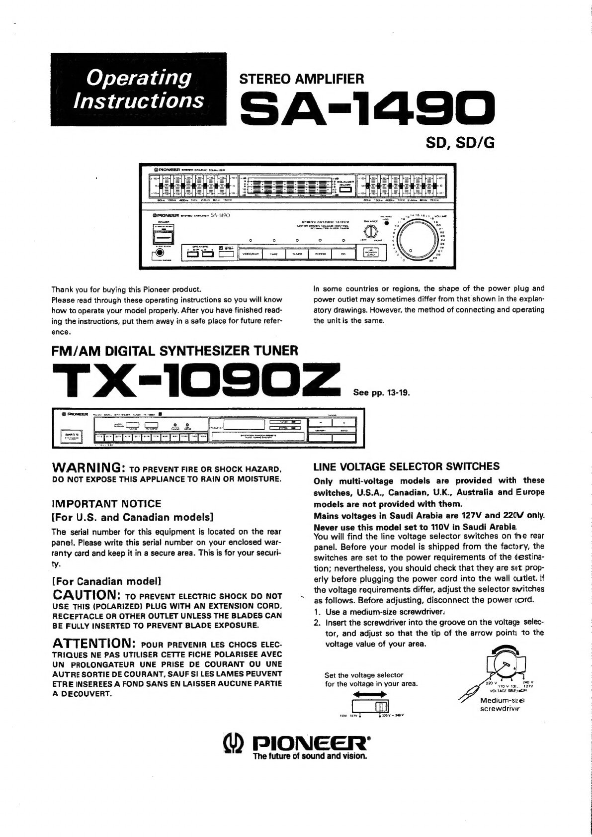
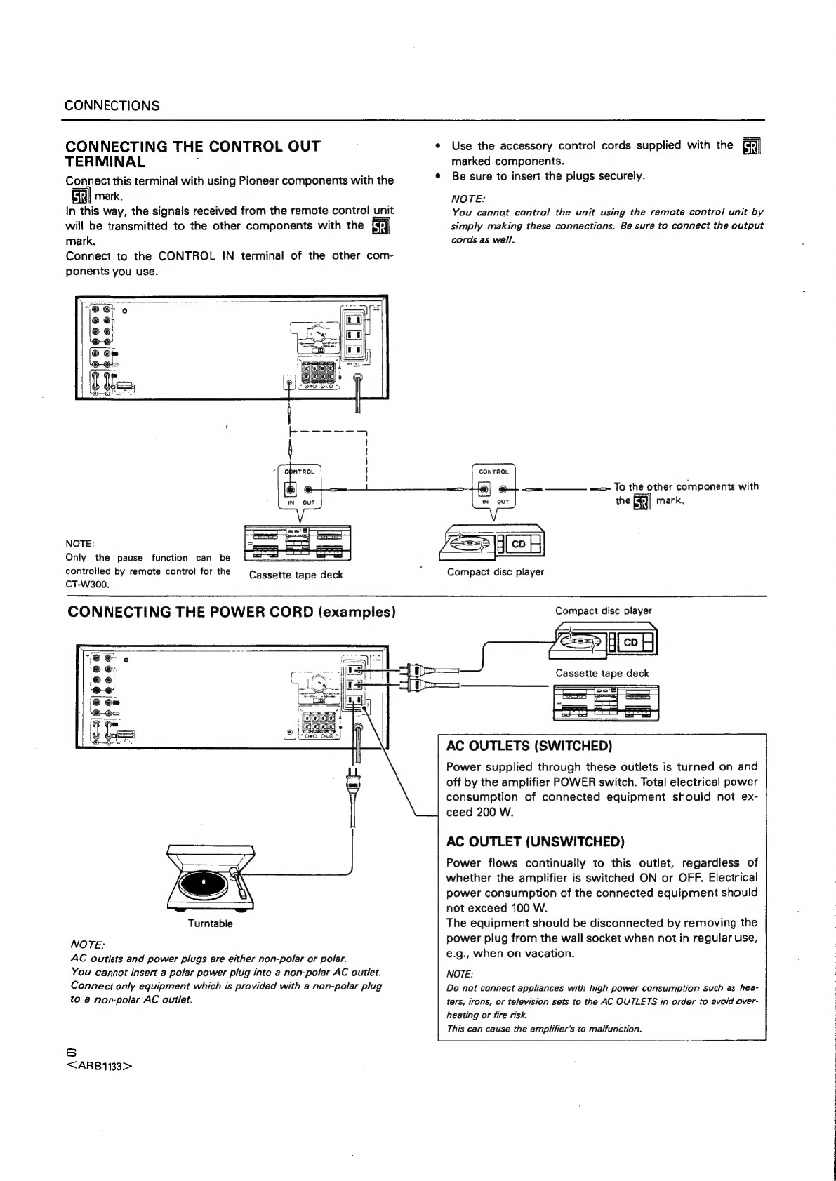
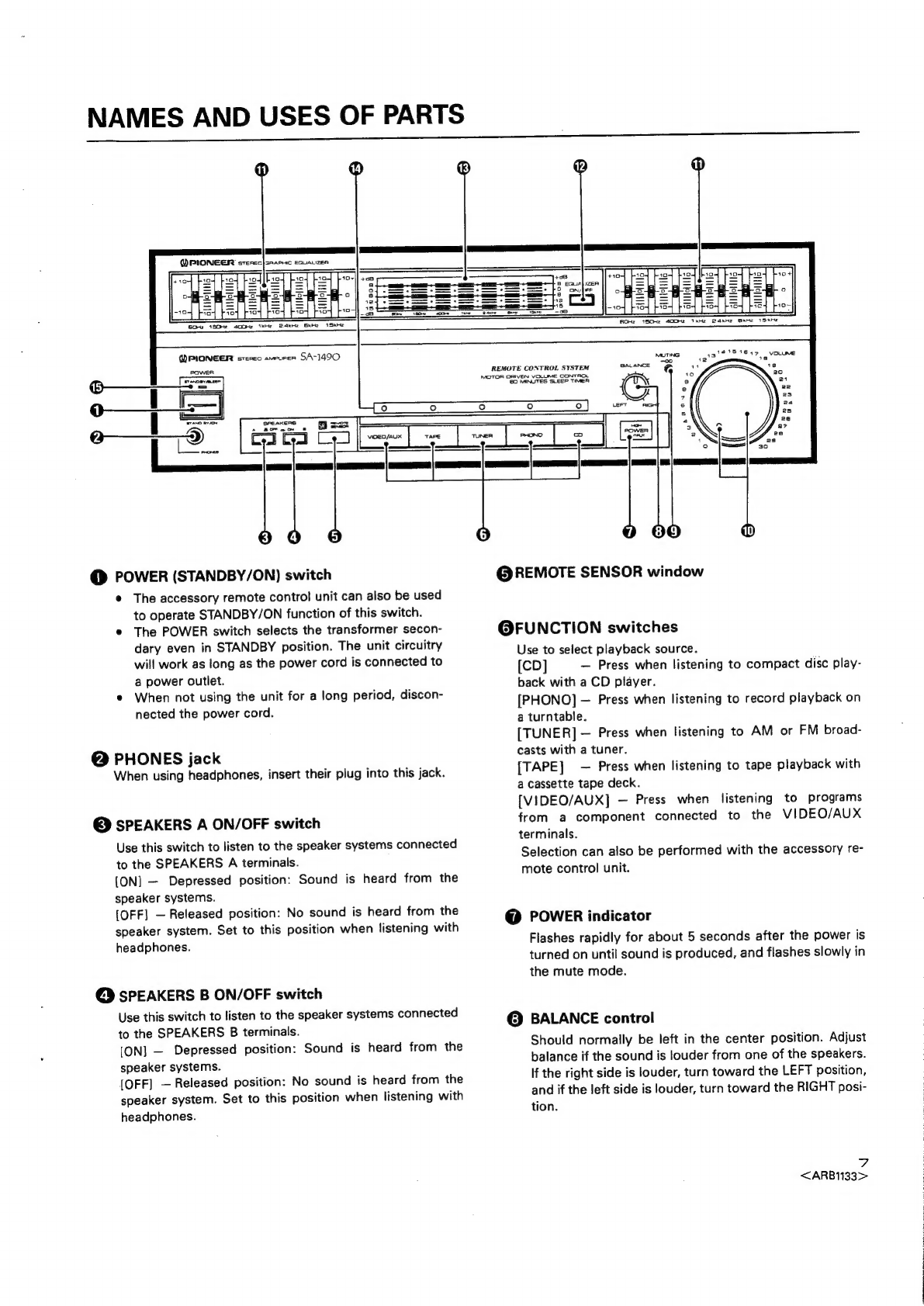
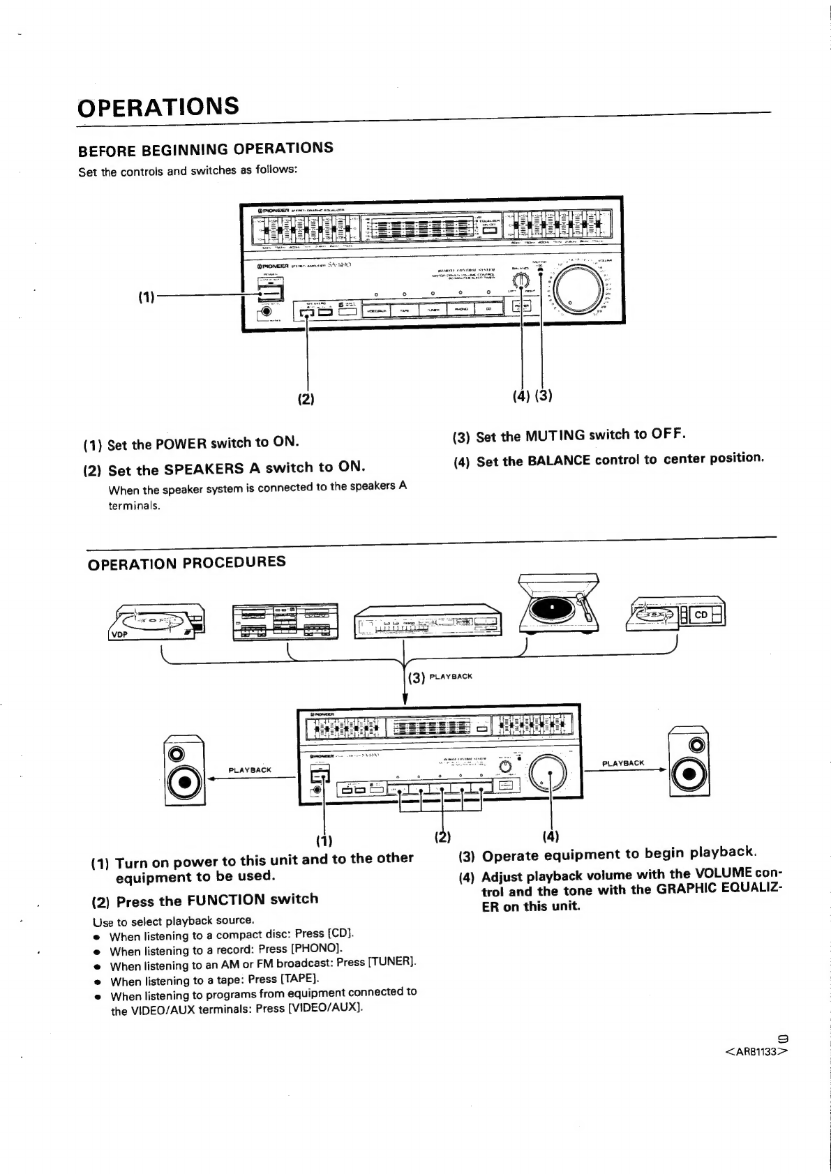
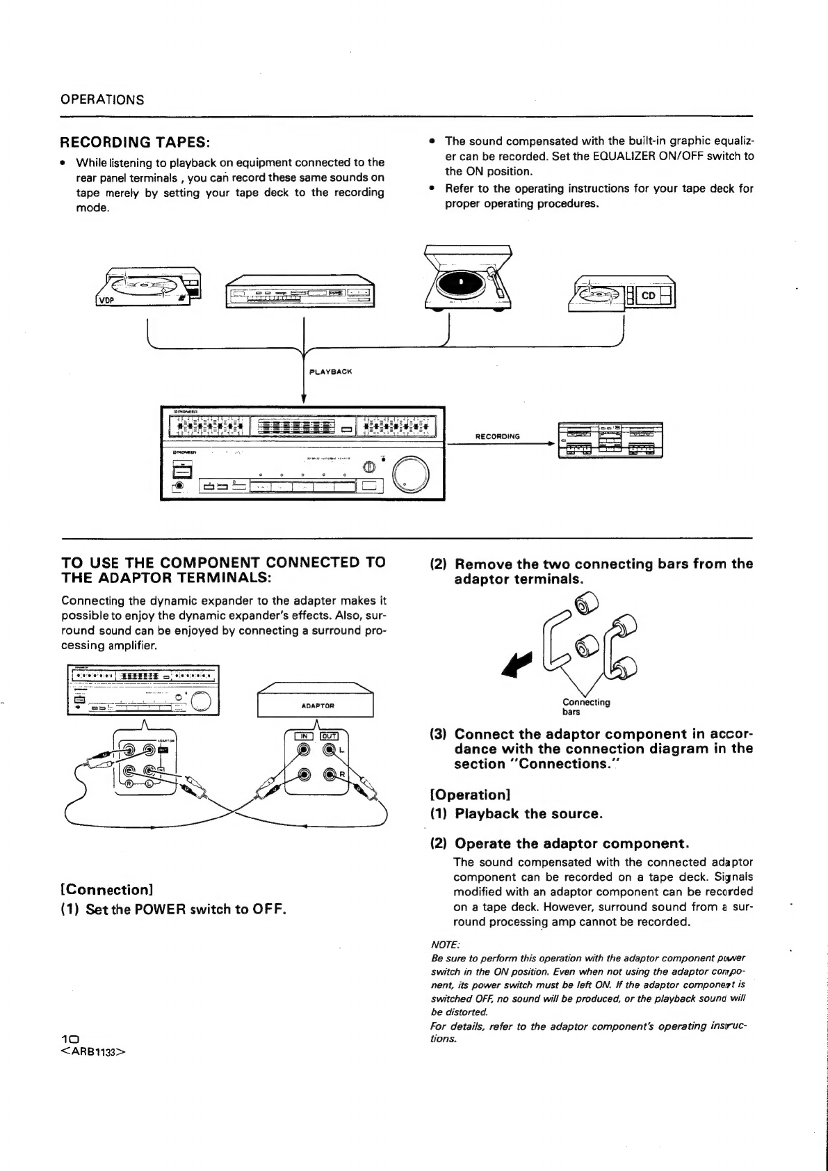
Pioneer SA-1490 User manual
Other Pioneer Amplifier manuals

Pioneer
Pioneer A-443 User manual

Pioneer
Pioneer GM-620 User manual

Pioneer
Pioneer GM-D505 User manual

Pioneer
Pioneer GM-6100F User manual

Pioneer
Pioneer PRS-D3000SPL User manual

Pioneer
Pioneer A-757 User manual

Pioneer
Pioneer GM-D510M/X1R/EW User manual

Pioneer
Pioneer SA-508 User manual

Pioneer
Pioneer PRS-A700 User manual

Pioneer
Pioneer GM-D8704 User manual

Pioneer
Pioneer DC-X82 User manual

Pioneer
Pioneer GM-3000T User manual

Pioneer
Pioneer PRS-D5000SPL User manual

Pioneer
Pioneer GM-D515 User manual

Pioneer
Pioneer VSA-AX10Ai User manual

Pioneer
Pioneer A-88X User manual

Pioneer
Pioneer GM-X362 User manual

Pioneer
Pioneer C-73 User manual

Pioneer
Pioneer M-LA21 User manual

Pioneer
Pioneer A-400 User manual