SigTEL EVC302RPO User manual
EVC302RPO, EVC302RLK
SigTEL Type A Fire Telephone Outstation Instructions
1 of 2
Approved Document No. DAU0000301 Rev 1 01/05/2023
THIS EQUIPMENT MUST ONLY BE INSTALLED AND MAINTAINED BY A SUITABLY SKILLED AND TECHNICALLY
COMPETENT PERSON. ENSURE THAT ALL POWER IS REMOVED FROM THE SYSTEM BEFORE INSTALLATION.
INSTALLATION
Location
Type A outstations should be sited indoors at entrances and fire-fighting lobbies for fire-fighters and persons
controlling evacuations in an emergency. Typically they are wall mounted 1.3 m to 1.4 m above the final floor level.
The outstations should be well-illuminated, easily accessible, prominent and free from obstruction. Ideally, the
outstation should be located where background noise is relatively low (no more than 50 dBA).
In sports stadiums they should be located no more than 30 metres from stewards’ positions or other normally
manned areas, as listed in the Guide to Safety at Sports Grounds.
First Fix
This document provides supplementary information to that provided in the main SigTEL 4-224 Line Controller
Installation and Configuration Manual (Document No. DAU0000091). For further details, refer to the main manual.
SigTEL
Emergency Voice
Communication System
EVC302RPO/RLK
Phone
Housing
Phone
Handset
2 x fixing screws
(top, underside)
EVC302RPO
EVC302RLK
Note: Emergency Voice Communication System (EVCS) design is beyond the scope of this document. An understanding of EVCS
components and their use is assumed. The following regulations apply to this product:
– BS 5588 Fire precautions in the design, construction and use of buildings; Part 5 Access and facilities for fire-fighting, Part 8
Code of practice for means of escape for disabled people, Part 10 Code of practice for shopping complexes, Part 11 Code of
practice for shops, offices, industrial, storage and other similar buildings.
– BS 5839 Part 9 Fire detection and alarm systems for buildings. Code of practice for the design, installation, commissioning
and maintenance of emergency voice communication systems.
– The Building Regulations, Approved Document B (fire safety) Volume 2, section 3 Design for vertical escape.
– Fire telephone systems for sports venues are called for by the Guide to Safety at Sports Grounds ‘Green Guide’.
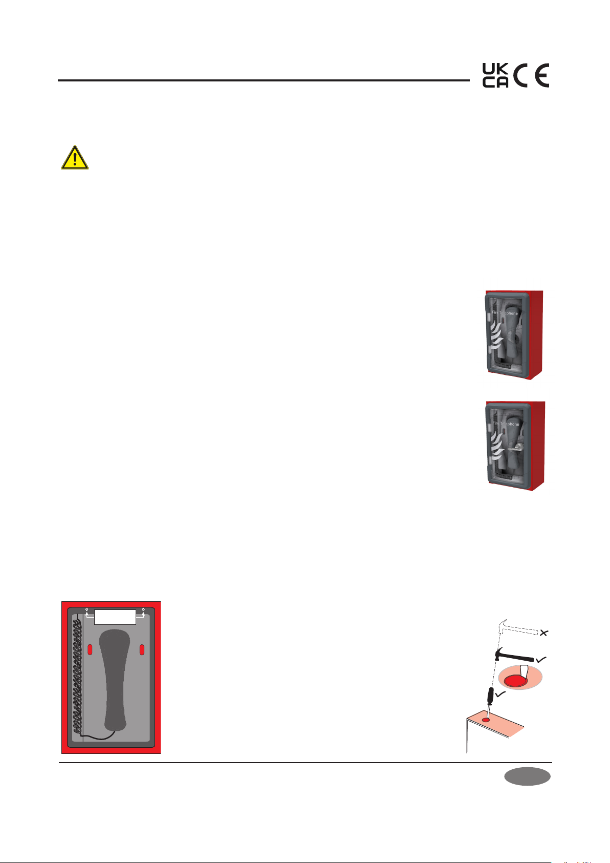
For the first fix, open the outstation’s door and remove the two
fixing screws at the top and underside of the internal phone
housing (see left). Pull out the phone housing and handset
(without using hand tools) to reveal the outstation’s fixing holes
and terminals. Disconnect the handset’s red wires at the terminals
(see diagram overleaf). Remove the phone housing and keep it in
a safe place.
The incoming cable from the EVCS controller will be fed into the
outstation’s enclosure via one of the 20 mm knockouts located in
the unit’s top and bottom. Remove knockouts with a sharp, light
tap using a flat 6 mm flat-sided screwdriver (see right). Always
ensure that if a knockout is removed, the hole is filled with a good
quality 20 mm, strain relief, cable gland. Any unused knockouts
must be securely blanked off.
PRODUCT DESCRIPTION
The SigTEL Type A Fire Telephone Outstation is part of an EVC fire telephone system providing
reliable two-way communication in a fire emergency between a permanently manned control
room and strategic points on the site.
The outstation consists of a telephone-style handset housed within a wall mounted, red mild
steel enclosure with a plastic door. Two versions are available, a “pull-to-open” version and a
“lift key lockable” version which prevents unauthorised access. If the lockable version is used,
the person responsible for the EVCS must hold the key. Both versions can be surface mounted or
flush mounted using a bezel.
The Type A outstation product range is listed below:
EVC302RPO: Red fire telephone outstation c/w handset, mild steel, plastic door (pull-to-open).
EVC302RLK: Red fire telephone outstation c/w handset, mild steel, plastic door (lift key lockable).
T-BEZ302: Red bezel for flush mounting the EVC302RPO/RLK, mild steel.
2 of 2
Testing and Wiring Outstation Lines
Outstation lines require 2-core enhanced fire-rated cable, size 1.0 mm2to 1.5 mm2. The maximum recommended
cable resistance is 40 ohms, which is 1 km of 1 mm2cable. If exceeded, outstations may not work correctly, e.g. audio
quality may degrade and the fault monitoring system may not work.
CAUTION: DO NOT test wiring using an insulation resistance tester (Megger) with any electronic equipment
connected. The 500 volt test will destroy the components, which the factory warranty will not cover.
Test all outstation lines for faults BEFORE termination. In addition, test outstation
lines using a SigTEL FITT telephone line tester.
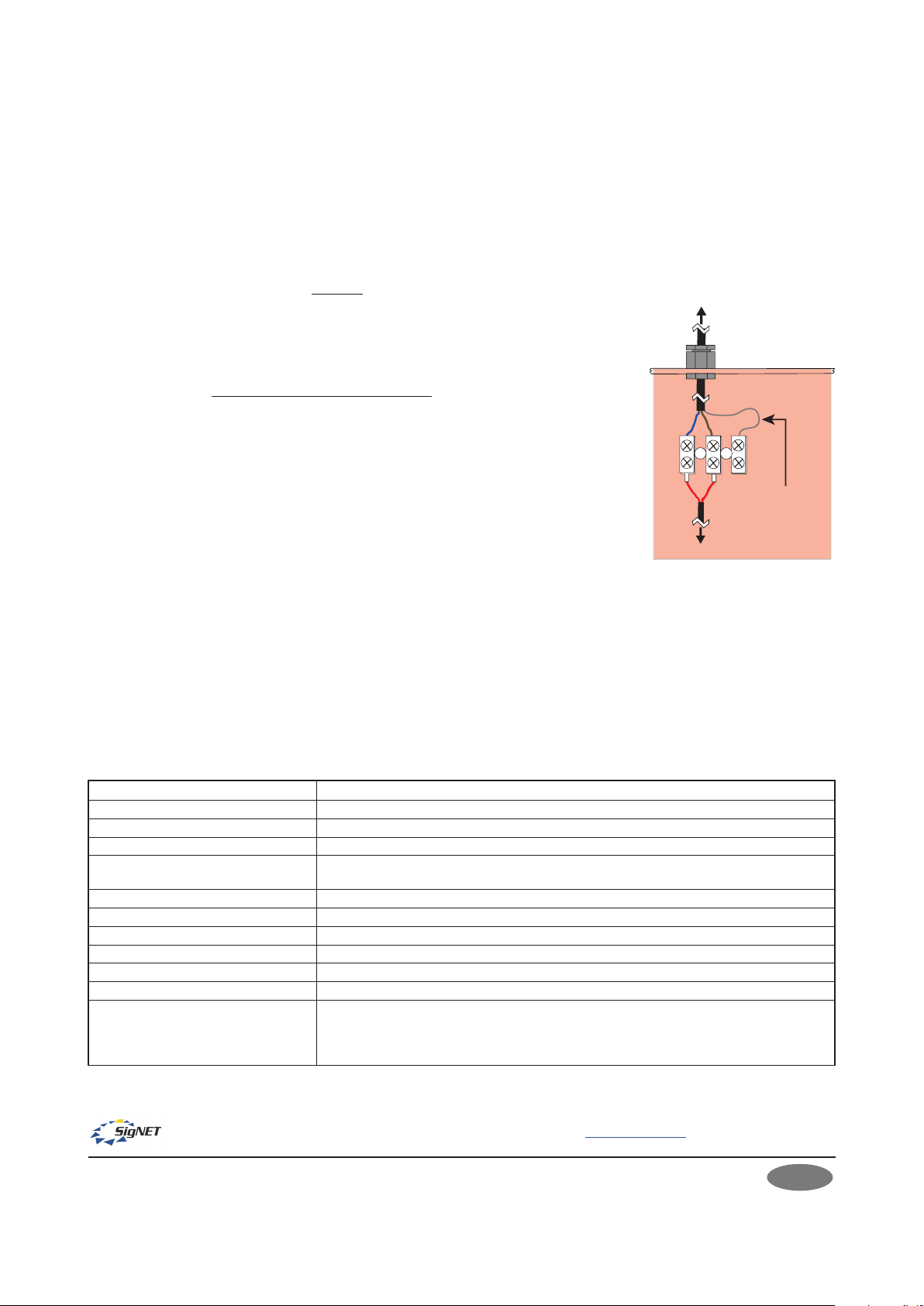
After testing outstation lines, terminate the cable from the EVCS controller at the
outstation’s terminals and reconnect the handset’s wires at the same terminals (see
right).
Secure the outstation’s internal phone housing back in position by pressing firmly on
the phone housing whilst avoiding trapping any wires. Reinsert the two fixing screws.
Refer to the main installation manual for connections at the EVCS controller.
Commissioning the Outstation
Perform an automatic configuration at the master EVCS controller to enable the
system to search for connected outstations. Refer to the main installation manual
for commissioning procedures.
OPERATION
Making a Call from the Outstation
Open the outstation’s door and lift the handset off-hook. The outstation will automatically call the operator in the
control room and a ‘beep-beep’ ringing tone sounds in the outstation’s earpiece. In the control room, the operator
is notified of the incoming call and can choose to answer. An engaged tone (continuous short pips) sounds in the
earpiece if the operator is talking to another outstation. When the call is answered in the control room the ringing
tone stops and a two-way conversation can commence. To end the call, simply replace the handset back on-hook.
Receiving a Call at the Outstation
When the operator in the control room calls the outstation, a pulsed ringing tone is heard at the outstation and the
red LEDs flash. Open the outstation’s door and lift the handset. The ringing tone stops and a two-way conversation
can commence.
TECHNICAL SPECIFICATION EVC302RPO/EVC302RLK
E&OE. No responsibility can be accepted by the manufacturer or distributors of this product for any misinterpretation of this instruction or the
compliance of the system as a whole. The manufacturer’s policy is one of continuous improvement and we reserve the right to make changes to
product specifications at our discretion and without prior notice.
SigTEL
Emergency Voice
Communication System
To EVCS controller
BrownBlue
Red
To handset
Outstation’s phone
housing removed
Red Screened cable is
shown terminated
but is not used
Input voltage (from EVCS controller): 10.7 V DC quiescent, 5 V DC in use
Current consumption @24 VDC: 1 mA quiescent, 25 mA in use
Microphone frequency response: 250 Hz to 5 kHz ± 3 dB
Earpiece frequency response: 250 Hz to 4 kHz ± 3 dB
Cable type (from EVCS controller): 1 x 2-core enhanced fire-rated cable, size 1.0 mm2to 1.5 mm2.Maximum cable resistance
is 40 ohms per line, which is 1 km of 1 mm2cable.
Cable knockouts: 4x20 mm diameter
Dimensions/weight: 297 mm(h) x 175 mm(w) x 102 mm(d). Weight: 2.2 kg
Fixing centres: 240 mm (h) x 120 mm(w)
Enclosure construction: Mild steel back box (red RAL 3000) & plastic door
IP rating (to BS EN 60529): IP21
Bezel (T-BEZ302) overall dimensions: 338.5 mm(h) x 216.5 mm(w) x 20 mm(d). Exposed thickness 1.2 mm.
Operating conditions:
The outstation’s enclosure is designed for indoor use only in accordance with BS 5839-9.
The outstation components must not be subjected to conditions likely to affect their
performance, such as dampness, salt air, water, extreme temperatures, physical abuse, etc.
Temperature range: -5oC to + 40oC. Max. relative humidity: 95% non-condensing.
Manufacturer: SigNET AC Ltd, 6 Tower Road, Washington, Tyne & Wear NE37 2SH. www.signet-ac.co.uk.
Mounting
Using the four mounting holes provided, fix the outstation to a wall using suitable screw fixings. Any dust or swarf
created during the mounting process must be kept out of the outstation, and care must be taken not to damage any
wiring or components. If a T-BEZ302 bezel is used, then glue the bezel to the hole in the wall using a mastic adhesive.
Approved Document No. DAU0000301 Rev 1 01/05/2023
This manual suits for next models
1
Table of contents


