Silence Aircraft Twister Kit User manual

Revision1.6
ii
Silence-Aircraft GmbH,
Kapellenweg 54a,
33415,
Verl
Germany
Aircraft Assembly
Manual
TwisterKit
Revision 1.6

Revision1.6
iii
Table of Contents
0. Using this Manual
1. General
1.1 Specifications
1.2 Materials and Tools
1.3 Fiber Composite Basics
1.4 Safety
2. Wings
2.1 Flaps
2.1.1 Installing the Hinge Pin for the Flap and the Aileron
2.1.2 Installing the Connecting Pins
2.1.3 Installing the Counterweight
2.1.4 Laminating the Seams and Ribs
2.2 Ailerons
2.2.1 Installing the Hinge Pins
2.2.2 Installing the Aileron Horns with Self-Aligning Bearings
2.2.3 Installing the Counterweights
2.2.4 Laminating the Seams and Ribs
2.3 Wings
2.3.1 Installing the Outboard Self-Aligning Bearing for the Aileron
2.3.2 Installing the Mounting Bearing for the Flap
2.3.3 Installing the Root Rib
2.3.4 Cutting the Holes for the Counterweights
2.3.5 CuttingtheWheelWell
2.3.6 Installing the Fuel Tanks
2.3.7 Installing the Aileron Drive
2.3.8 Installing the Flap and the Aileron
2.3.9 Installing the Bearing Sleeve for the Front Wing Torsion Pin
2.3.10 Laminating the Seams and Ribs
2.3.11 Installing the Pitot Tube (for Airspeed Indicator)
2.3.12 Installing the Position Lights (Optional)
3. Fuselage
3.1 Reinforcing the safety cell around the lap safety belt

Revision1.6
iiii
3.2 Installing the flap mechanism and the supports for the wing torque tube
3.3 Installing the landing-gear struts, wheels and fairings
3.4 Installing the landing-gear actuator
3.5 Installing an undercarriage warning systemPFA MOD 329/007
3.6 Installing the horizontal stabilizer with securing wire
3.7 Installing the ribs in the rudder assembly
3.8 Mounting the wings
3.9 Installing the fuselage base
3.10 Installing the elevator bellcrank
3.11 Assembling the rudder
3.12 Installing the upper rudder bearing
3.13 Assembling and installing the rudder drive in the rudder
3.14 Installing the rudder pedals
3.15 Assembling and installing the tail wheel
3.16 Assembling and installing the control stick
3.17 Installing the elevator push rods incorporating PFA MOD 329/003
3.18 Assembling and fitting the canopy
3.19 Installing the NACA air supply
3.20 Installing the trim
3.21 Laminating the seams and reinforcing the wheel well
3.22 Installing the baggage compartment cover, safety belt and seat pan
3.23 PFA MOD 329/008 Parachute Seatback
4. Tail
4.1 Installing the Root Ribs and Laminating the Seams
4.2 Inserting the Outboard Hinge Pin and the Self-Aligning Bearing
into the Fin
4.3 Installing the Elevator Supports
4.4 Installing the Fiberglass Hexagon Tube and the Root Rib into
theElevator
4.5 Installing the PlainBearing for the Front Elevator Torsion Tube
5. Motor
5.1 Painting and Masking the Firewall
5.2 Installing the Engine Mount on the Firewallincluding PFA MOD329/005
5.3 Installing the Engine on the Engine Mount

Revision1.6
ivi
5.4 Installing the Cooling Air Ducts
5.5 Installing the Air-Intake Casing
5.6 Installing the Crankcase Ventilation with Separator
5.7 Mounting the Propeller and the Spinner
5.8 Assembling the Throttle and Brake Assembly
5.9 Installing the Control Cables on the Engine
5.10 Installing the Tank and Fuel System Incorporating PFA MOD 329/002
5.11 Installing the Cowling
6. Avionics
6.1 Selecting and Arranging the Instruments
6.2 Creating the Cut-Outs in the Instrument Panel
6.3 Rounding the Cut-Out Edges
6.4 Laminating the Instrument Panel
6.5 Installing the Instrument Panel in the Fuselage
6.6 Creating the Structure behind the Instrument panel
6.7 Wiring Loom
6.8 PFA MOD329/001Removing and disabling Emergency Flap lowering switch
System
7. Surface Treatment and Painting
7.1 Filling and Sanding the Surface
7.2 Filling and Sanding the Seams
7.3 Priming
7.4 WetSanding
7.5 Painting/Paint Selection

Revision1.6
vi
0Using this Manual
Note: This manual was translated from a German original.
Measurements
The design of the Twister is based on the metric system. All US conversions given in the text are
for guidance only. All dimensions in the figures are in millimeters (mm) unless otherwise stated.

Revision1.6
ii
Part Numbers
The part numbers refer to the bill of materials, which is delivered as a separate document.
Printing the Manual
The layout of this manual is adjusted for letter size paper.
Abbreviations
CF cotton flock
MB microballoons
FRP fiber-reinforced plastic
FC fiber composite
UD unidirectional
General guide line for the installation of bolts.
It is standard aircraft practice to always orient bolts pointing down, outboard, or aft, when possible.
Also, the bolt grip length should equal the material thickness it is going through to avoid having the
threads in bearing, and when using self locking nuts, make sure there are at least 1-1/2 threads
showing.
You should not be able to thread the nuts on by hand, if so the locking feature is worn out. The best
practice it to not reuse self locking nuts or at least minimize their re-use. When securing with
Loctite, always mark it with witness paint, indicating it has been secured with Loctite.
If you need to remove a fastener secured with Loctite use a heat gun to soften the bonding agent so
not to cause damage to the threads.
If a bolt is not clamping or the material it is going through is rotating against the bolt, a castle nut
and cotter pin must be used.
Revision1.6
1.1
General
1
1.1 Specifications
The Twister kit consists of structural components made from honeycomb fiber glass composites,
with spars and additional reinforcements made of carbon fiber reinforced plastic. For extra safety, an
aramid honeycomb monocoque (cockpit cell) is used.
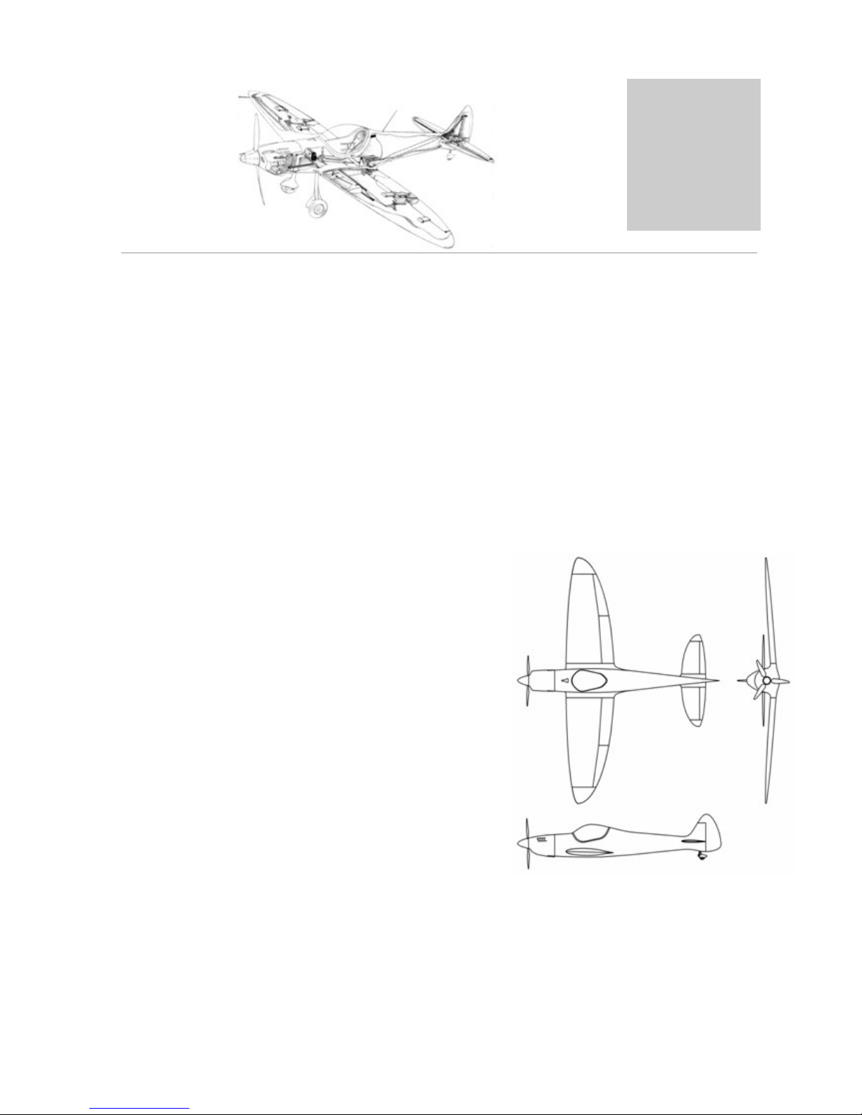
The Twister is an aerobatics-capable cantilever low-wing plane with cruciform tail unit, retractable
two-wheel landing gear and flap system. Optionally a rescue system can be installed in the cockpit cell.
There are two fuselage variants: one prepared for mounting a rescue system and one for use without a
rescue system.
Wing span: 7.5 m (24.6 ft)
Length: 6.18 m (20.28 ft)
Wing area: 8.718 m² (93.84 sq ft)
Max. take-off weight (MTOW): 420kg (881.95 lb)
Max. wing loading: 40.15 kg/m² (8.22lb/sqft)
Elevator span: 2.8 m (9.19 ft)
Elevator area: 1.65m² (17.76 sqft)
Crew: 1
Engine: Jabiru 2200

Revision1.6
1.2
General
1
Strength
The Twister is certified for the following load factors:
+6 / -4g at 400 kg (882 lb) take-off weight at 209 km/h (113kt/130 mph) maneuvering speed
Do not exceed these load factors. Especially, avoid wide rudder movements at speeds above
209km/h (113kt/130 mph).
Maximum Flight Speeds
Speeds converted for sea level
Stall speed, 30° flaps: VSF 75kph (40.47kt/46.60mph)
Stall speed, no flaps: VS85kph (45.87kt/52.82mph)
Maneuvering speed: VA209kph (112.78kt/129.87mph)
Maximum speed: VNE 300kph (161.88kt/186.41mph)
VD330kph (178.07kt/205.05mph)
Maximum speed, 30° flaps: VFE 125kph (67.45kt/77.67mph)
When using a rescue system, the maximum speed is limited to the maximum speed specified for the
rescue system.
Load calculations are based on JAR23.

Revision1.6
1.3
General
1
1.2 Materials and Tools
The Twister is primarily built from fiber composites. The structural honeycomb sandwich
components are vacuum molded by the manufacturer.
The builder has to carry out the following tasks:
-Laminating joint tapes
-Adjusting and installing the ribs into the structural components
-Sanding and filling the surfaces
-Mechanical assembly
-Wiring/laying the wire harnesses
-Painting
If you are not sure about the tasks listed above, ask aprofessional.
Important: If any component is damaged, e.g. by sanding through the fiberglass skin,
contact the manufacturer in order to determine whether the component can still be used or
can be repaired!
To build the Twister you need a work area measuring at least8m x 4m (26ft x 13ft). With an area
this size you will need mount the wings to the fuselage in the outside.

Revision1.6
1.4
General
1
The following table lists all fiber composites used in the Twister. Materials printed in blue have to
be applied by the builder.
List of Fiber Composites Used In the Twister
Fabrics
Description Weave type Finish Interglas
no. Fabric
width
Fiberglass fabric 105g/m² Twill FK144 91111 1000mm
(39.37")
Fiberglass fabric 163g/m² Twill FK144 92110 1000mm
(39.37")
Fiberglass fabric 280g/m² Twill FK144 92125 1000mm
(39.37")
Fiberglass fabric 296g/m² Twill FK144 92626 1000mm
(39.37")
Aramid fabric 170g/m² Twill Washed -1000mm
(39.37")
Carbon fabric 200g/m² Twill --1000mm
(39.37")
Carbon fabric 245g/m² Twill --1000mm
(39.37")
Carbon fiber tape 125g/m² UD Epoxy -25mm
(0.98")
Carbon fiber tape 300g/m² UD Epoxy -50mm
(1.97")
Carbon fiber tape 300g/m² UD Epoxy -75mm
(2.95")
Peel-ply 100g/m² Twill --500mm
(19.69")
Peel-ply 95g/m² Linen --500mm
(19.69")
Peel-ply tape 95g/m² Linen --60mm
(2.36")
Fiberglass tape 10g/m² 30° braid --25mm
(0.98")
Fiberglass tape 20g/m² 30° braid --40mm
(1.57")
Carbon fiber roving 1610 Tex -Epoxy --

Revision1.6
1.5
General
1
Resin / Hardener
Scheufler L285 + H286
Cyanoacrylate glue ("super glue"), medium
viscosity
Fillers
Cotton flock
Thixotropic agent (Cabosil or equivalent)
Glass bubbles 0.12g/cm³ (119.86oz/cu ft)
Micro balloons
Support Materials
Description Thickness Density
Aramid honeycomb, 3.2mm (0.13") cell
diameter 3mm (0.12")
48kg/m³
(3lb/cu ft)
Aramid honeycomb, 3.2mm (0.13") cell
diameter 3mm (0.12")
29kg/m³
(1.81lb/cu
ft)
Aramid honeycomb, 3.2mm (0.13") cell
diameter 5mm (0.20")
48kg/m³
(3lb/cu ft)
Aramid honeycomb, 3.2mm (0.13") cell
diameter 5mm (0.20")
29kg/m³
(1.81lb/cu
ft)
Aramid honeycomb, 3.2mm (0.13") cell
diameter 7mm (0.28")
48kg/m³
(3lb/cu ft)
Aramid honeycomb, 3.2mm (0.13") cell
diameter 10mm (0.39")
48kg/m³
(3lb/cu ft)

Revision1.6
1.6
General
1
Tools
To build the Twister you need the following tools:
-Paint brush
-Scissors
-Power drill
-Pop rivet pliers
-Set of wrenches and screwdrivers
-Torque wrench
General Torques forScrew/Bolt Connections
(Bolts/screws slightly greased)
M5 5Nm
M6 9Nm
M8 23Nm
M10 46Nm
-Twist drill set, 1-12mm (.040"-0.50")
-Long nose pliers, long type
-Caliper gauge
-Set of files
-Sanding paper (80, 100, 220, 500 wet sanding paper)
-2 ratchet straps, each 8m (25 ft) long
-Rotary grinding/cutting tool (e.g. Dremel)
-Reciprocating saw (e.g. Jig Saw)
-Orbital DA sander
-Spray gun
-Vise (5”or 6”clamping length)
-Tape measure (metric)
-Wooden stir sticks (e.g. tong depressors)
-Mixing cup (un-waxed)
-Disposable protective gloves (Latex or Nitrile)
-100º countersink
-Scales 0-2,000g (0-oz), 0.5g (0.02oz) precision (balance beam or electronic)
-Nicopress tool (e.g. from Aircraft Spruce)
-Mold release wax
-Polypropylene packaging tape, 50mm (2") wide
-Keyhole saw 25-70mm (1"-2.75")
-Level, ca. 300mm (12") long

Revision1.6
1.7
General
1
1.3 Fiber Composite Basics
Plastics in General
For thousands of years human existence depended on natural materials. Clothing, tools, and utensils
were made from leather, metal, stone, clay and other substances provided by nature.
Most manmade materials like porcelain, glass, and metal alloys were discovered more or less by
accident.
When important raw materials started to become scarce and expensive at the beginning of the 20th
century, an intensive search for synthetic (artificial) substitutes ensued. Natural materials alone could
no longer satisfy the emerging technical requirements of the fast-growing industries.
In the course of time a myriad of compounds, including numerous plastics, were synthesized from
natural raw materials such as coal, coal tar, crude oil, and natural gas.
Combining different materials to form a composite with enhanced properties and synergies is a
common process in nature: the section of a strand of merino wool or a bamboo stem shows
structures similar to the cross section of a unidirectional carbon fiber reinforced epoxy resin (CF-
EP). Nature remains the model not only for the microstructure of fiber reinforced plastics, but also
for the application of lightweight design principles.
The use of fibers as construction materials is based on the following four paradoxes of materials:
1. The Paradox of the Solid Material
The actual strength of a solid material is much lower than its calculated theoretical strength (F.
Zwicky).
2. The Paradox of Fiber Form
The strength of a material in fiber form is many times higher than that of the same material in
another form; the thinner the fiber, the greater the strength (A. A. Griffith).
3. The Paradox of the Free Clamped Length
The shorter the length between the clamps, the higher the measured strength of a sample (fiber).

Revision1.6
1.8
General
1
4. The Paradox of Composite Materials
When taken as a whole, a composite can withstand stresses that wouldbreak the weaker component,
whereas the composite’s stronger component can exhibit a greater percentage of its theoretical
strength than when loaded singly (G. Slayter).
Fiber Composites
The principle of combining different materials to form a composite with enhanced properties is just
as common in nature as in lightweight engineering.
This design method copied from nature has virtually revolutionized many fields of technology, with
the result that now for the first time extremely strong, but at the same time lightweight materials with
superior characteristics are available.
In particular the aerospace industries benefit from these low structural weights, which allow
considerable fuel savings and performance gains.
In space flight, high-performance fiber composites are used mainly for economic reasons. In view of
the high fuel costs, space agencies are prepared to spend up to 25,000 euros for every kilogram
saved. In aviation the figure is 250-750 euros per kg, in the automotive industry 0-2.50 euros per kg
(with the exception of racing).
As fiber composites are usually more expensive than compact materials (e.g. metals) and place higher
demands on design and processing technologies, there is little incentive to use them in normal
automotive engineering, whereas their benefits for the aerospace industries are obvious.
With falling prices and growing, more generally available processing know-how composites are now
widely used. Motor sports, model construction and sports equipment design today could hardly be
imagined without them.
Applications in mechanical engineering are also gaining ground.
The Principle
A fiber composite (FC) is the result of combining several materials:
1.) the matrix (e.g. epoxy or polyester resin), which gives shape to the final component, and
2.) the reinforcing, highly tensile fibers (usually glass, aramid, or carbon)
Revision1.6
1.9
General
1
Simply speaking, fiber composites can be compared with reinforced concrete, where a brittle, shape-
giving material (concrete) is reinforced by steel.
The fibers are embedded in a liquid mass of reactive resin and fixed in place when the resin hardens
in the mold. This technique can be used to manufacture even complex or very large parts in one
operation with relatively little effort.
The processing method is chosen according to the number and size of the parts to be manufactured
as well as structural strength requirements and other properties such as transparency, surface finish,
dimensional stability, etc.
The general rule is that a fiber composite results only from the combination of resin and fibers, i.e. it
is produced directly by the processor.
Therefore the properties of the end product depend almost entirely on careful processing and curing
as well as on component design (fiber orientation, fiber percentage, number of plies, and fabric).
Strength
The strength of a fiber composite is determined to a large extent by the reinforcing fiber.
Two types of strength are distinguished: static and dynamic.
Static strength is a measure of a material’s behavior under simple loads (tension, compression,
bending), whereas dynamic strength is a measure of a material’s behavior under frequent load
changes (bending cycles with variable force and frequency and the resulting combination of tensile,
compressive, and shear stresses).
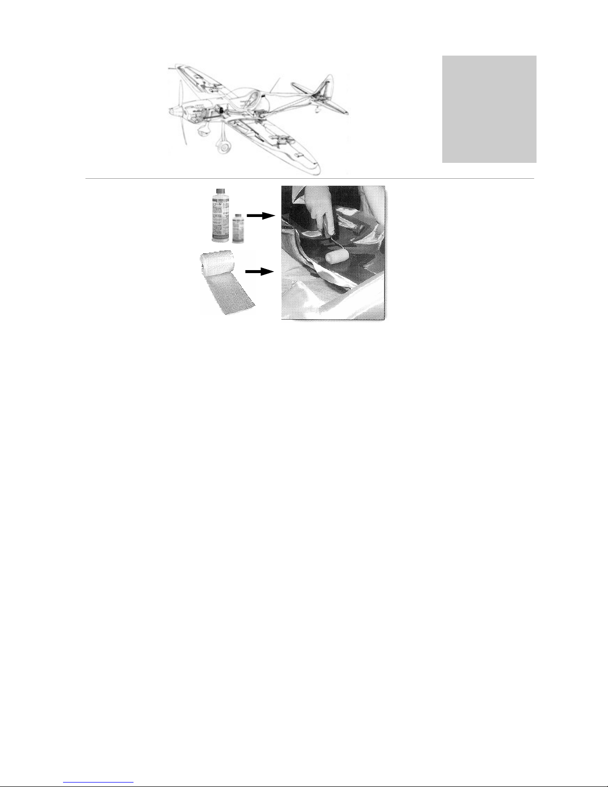
Manual lamination
using a foam roller

Revision1.6
1.10
General
1
A high dynamic strength is particularly needed for components which are subject to frequent
bending cycles (e.g. struts in aircraft construction).
Even after several tens of thousands load reversals, epoxy resins suffer only the smallest decrease in
strength and therefore have the highest dynamic strength.
Matrix
This is a reactive resin which acts as a binder, supporting the fibers and transferring to them the
forces acting on the molded part. This requires that the resin adheres well to the fibers.
Essentially, the reactive resin determines the following properties: chemical resistance, aging
resistance, scratch resistance, electrical properties, and shrinkage during curing.
Density, thermal conductivity, thermal expansion, and specific heat depend on the proportions of
reactive resin, curing agent, fibers, and fillers.
Fibers
The mechanical properties of molded materials, e.g. tensile, bending and impact strength, as well as
the ability to absorb energy, are mainly influenced by the fibers. These properties can be influenced
by the choice of fiber materials, the fiber content, and the orientation of the fibers.
Curing
The properties of the cured and molded reactive resin (i.e. of the molded part) depend not only on
the starting material, but also very much on the control of the curing process. Knowledge of the
processes involved in the curing of reactive resin is therefore crucial.
Curing, i.e. when the liquid compounds of reactive resin solidify into three-dimensionally cross-
linked products, can take place as one of three reaction types:
Polymerization
(e.g. unsaturated polyester resins)
Under the effects of reactive agents, e.g. peroxides and accelerators, the double bonds of the starting
components react with each other, releasing heat in the process. The molecules of the starting
components cross-link to form macromolecular structures called polymers.
When several starting materials, such as unsaturated polyester and styrene, are mode to react as
described above, the processis called copolymerization.

Revision1.6
1.11
General
1
Polymerization does not start until a certain time after the reactive agents have been added.
Thereafter the resin compound solidifies relatively quickly. This involves heat generation and a rapid
increase in viscosity, but no release of volatile products. Once started, the curing process cannot be
stopped or reversed.
Polyaddition
(e.g. epoxy resins)
Unlike polymerization, the polyaddition reaction requires the addition of a much higher quantities of
reactive agents, with the additional difference that these quantities are calculated on the basis of the
desired end-product.
Therefore the properties of the end product are influenced both by the reaction resin and the
reactive agent used. In polyaddition, the transition from the liquid to the solid state generally takes
place more slowly and uniformly than in polymerization. The reaction releases heat.
Polycondensation
(e.g. phenol formaldehyde resins)
In polycondensation, the reaction of the starting components releases by-products, e.g. water.
The reaction can controlled in a step-by-step process. In general precondensed resins are used, which
in most cases can be cured by applying heat.
Elongation at Break
When subjected to tensile stress, the resin must not break before the fibers. Otherwise, cracks in the
resin will cause the whole part to fail. The elongation at break of the resins should therefore always
be greater than that of the reinforcing fibers.
Adhesion Between Resin and Fibers
Another important factor in the quality of a composite is the adhesion between the resin and the
reinforcing fibers. Higher adhesion results in higher strength.
To facilitate adhesion, glass fabrics are treated with coupling agents (silanes, various finishes), which
allow the strongest possible (chemical) bonding to the resin.
The exceptions are aramid fibers (Kevlar®, Twaron®) and polyethylene yarns (Dyneema®), for
which no chemical coupling agents are available.
Carbon fibers are coated with epoxy resin.
Revision1.6
1.12
General
1
Glued Bonds
Cyanoacrylate-based glues (super glue) and epoxy resin show superior adhesion on various materials
and are used to bond plastics, metals, wood, glass, concrete, ceramics, etc.
The strength of a glued bond is determined by the following glue properties:
the strength of the adhesive (cohesion)
its “stickiness” on surfaces (adhesion)
Preparing the Surface
The bonding surfaces are cleaned in order to remove any adhering foreign matter, such as dirt, rust,
scale, paint, varnish, etc. The most common method of cleaning is by mechanical means (sanding
and brushing). Even for less severely loaded bonds cleaning the surfaces is essential in order to
achieve the desired bond strength, given that foreign matter is often the root cause of bond failure.
For this reason, peel-plies are applied on most bonding surfaces of the Silence. These
fabrics, which are marked by a blue or red thread, are pulled off by hand. The resulting
rough surface is ideal for bonding. After pulling off the peel-ply, do not touch or soil the
bonding surfaces.
Fitting
This step involves the removal of burrs and, in the case of large bonding surfaces, the parallel
alignment of the bonding surfaces of the parts.
Degreasing
Use organic solvents or hot (approx. 60-80°C [140-176°F]) water containing 1%-3% of a liquid
detergent to degrease surfaces. However, bear in mind that some detergents, e.g. dish-washing liquid,
can contain small quantities of silicone compounds, which as residues can prevent the glue from
wetting the surfaces properly.
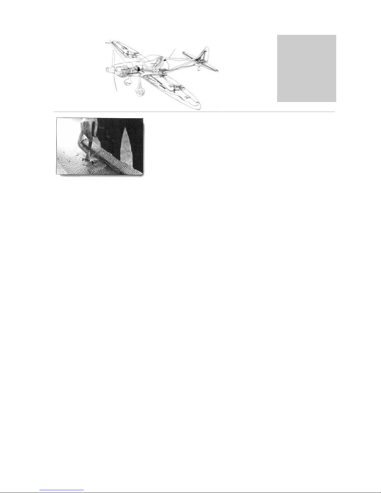
Manual lamination: carbon-
aramid fabric being
impregnated with epoxy resin

Revision1.6
1.13
General
1
Degreasing is one of the most important prerequisites for proper wetting, so it should be carried out
regardless of whether the surface will be treated further.
Suitable solvents are, among others, various alcohols and acetone. Although they were frequently
used in the past, do not use chlorinated hydrocarbons (CHC), such as chloroform, methylene
chloride, TRI, carbon tetrachloride, etc., unless it is absolutely necessary. CHC are harmful to health
and poorly biodegradable. Building the Silence does NOT require the use of CHC, so for the above
reasons they should not be used!

Revision1.6
1.14
General
1
To check for proper degreasing you can pour a few drops of distilled water on the surface:
Manual Lamination
Manual lamination (hand lay-up) is the oldest, simplest and most common method. The technical
requirements are minimal, so it is mainly used for minor series and simple part geometries, as well as
for building the Silence. The molded part is cured at room temperature without application of
pressure.
Ambient conditions of the working area: min. 20°C (68°F) room temperature, around 60% humidity,
good ventilation.
a) Poorly degreased:
b)Welldegreased:
Water collects into droplets
Water forms a
film
Part to be bonded
Table of contents


