Silent Sentinel RCF-KIT-FD384H Quick reference guide

Commercial in Confidence 1
SILENT SENTINEL ARE
SPECIALISTS IN LONG
RANGE OPTICAL
SENSORS INCLUDING BOTH COOLED AND UNCOOLED THERMAL CAMERAS
WHEREVER SURVEILLANCE MATTERS SILENT SENTINEL PROVIDE
CLARITY AND VISION
SILENT SENTINEL ARE SPECIALISTS IN LONG RANGE
OPTICAL SENSORS INCLUDING BOTH COOLED AND
UNCOOLED THERMAL CAMERAS
TITLE GOES HERE
Fixed MODEM - Deployment Guide Kit, Tripod

Commercial in Confidence 2
Silent Sentinel Limited reserves all the right. All in this manual including texts, pictures,
diagrams and other contents belong to Silent Sentinel Limited. Without the written
permission, no one shall copy, photocopy, translate or disseminate all or part of this manual.
This manual is used as a guide. The photos, graphics, diagrams and illustrations provided in
the manual are only used for explanation, which may be different from the specific product.
Please refer to the actual product. We try our best to make sure all the contents in this
manual are accurate. We do not provide any representations or warranties in this manual.
If you need the latest version of this manual, please contact us. Silent Sentinel recommends
that you use this manual under the guidance of professionals.
Version Control
Version
Author
Approver
Date
1.0
Matthew Short
Paul Elsey
11th April 2020

Commercial in Confidence 3
Contents
Introduction...................................................................................................................................................... 4
Equipment List.................................................................................................................................................. 4
Complete Kit Tripod................................................................................................................................... 4
Physical Setup Guide ........................................................................................................................................ 6
Mounting the MODUM Camera................................................................................................................... 6
Deploying the Blackbody.............................................................................................................................. 7
Complete Assembly...................................................................................................................................... 7
Installation Information.................................................................................................................................... 9
Wiring Guide................................................................................................................................................. 9
MODUM Camera System......................................................................................................... 9
Thermal Blackbody................................................................................................................... 9
Deployment Suggestions................................................................................................................................ 10
Deployment Notes...................................................................................................................................... 10
Typical Deployment Scenario ..................................................................................................................... 11

Commercial in Confidence 4
Introduction
The aim of this document is to details the steps required to physically deploy the Fixed MODUM
Capability.
Equipment List
Complete Kit –Tripod
The following equipment makes up the Complete Kit –Tripod;
Part Number: RCF-KIT-FD384H / RCF-KIT-FD640H
Serial
Description
Part
Number
Image
1.
MODUM Camera System
2.
MODUM Ethernet Cable
(3m) –Camera to Laptop
3.
MODUM Power Supply
4.
MODUM Tripod
5.
MODUM Tripod Extension
Pole


Commercial in Confidence 6
Physical Setup Guide
Mounting the MODUM Camera
Step
Description
Image
1.
Separate the MODUM Extension
Mount into it’s two parts
2.
Fix the show part into the underside
of the MODUM Camera.
3.
Fix the show part Camera Mount
point on the Tripod
4.
Slide both parts of the mount back
together. Adjust the MODUM so it is
facing forwards and tighten the
locking thread.

Commercial in Confidence 7
Deploying the Blackbody
Step
Description
Image
1.
Separate the MODUM Extension Mount into it’s
two parts
2.
Fix the show part into the underside of the Black
Body.
3.
Fix the show part to the top of the Tripod
4.
Slide both parts of the mount back together.
Adjust the Black body is facings towards the
camera.
Complete Assembly


Commercial in Confidence 10
Deployment Suggestions
Deployment Notes
General
1. The system should be deployed indoors in a relatively stable ambient temperature.
2. Any quick changes in temperature will impact on the blackbodies ability to regulate its surface
temperature. This will then have an impact on the accuracy of the system
3. If the system is to be deployed outdoors then protect from the environment by installing inside
a container / tent.
4. Avoid areas that have a number of high temperature objects in the FOV. If any present, use
the shield zones to shield them out.
5. Avoid placing directly at the entrance from the outside. Force the person to walk through a
channel first before screening. This will allow enough time to reduce the impact on their skin
temperature based on the outside conditions.
MODUM Camera
1. The MODUM Camera should be deployed around 2m from the people to be screened.
2. For best performance the MODUM Camera should be roughly head-height of the people to
be screened minimising the angle of incidence to their faces as much as possible.
Black Body
1. The Black Body should be deployed towards to top of the Field of View (FOV) of the MODUM
camera in an area that will not be obstructed.
2. Deploy as close to the range you want to screen at. I.e., if the people are to be screened at
2.5m deploy the blackbody at that range.
3. Avoid areas with high air flow. This may impact on the black bodies ability to maintain it’s
temperature.
Commercial in Confidence 11
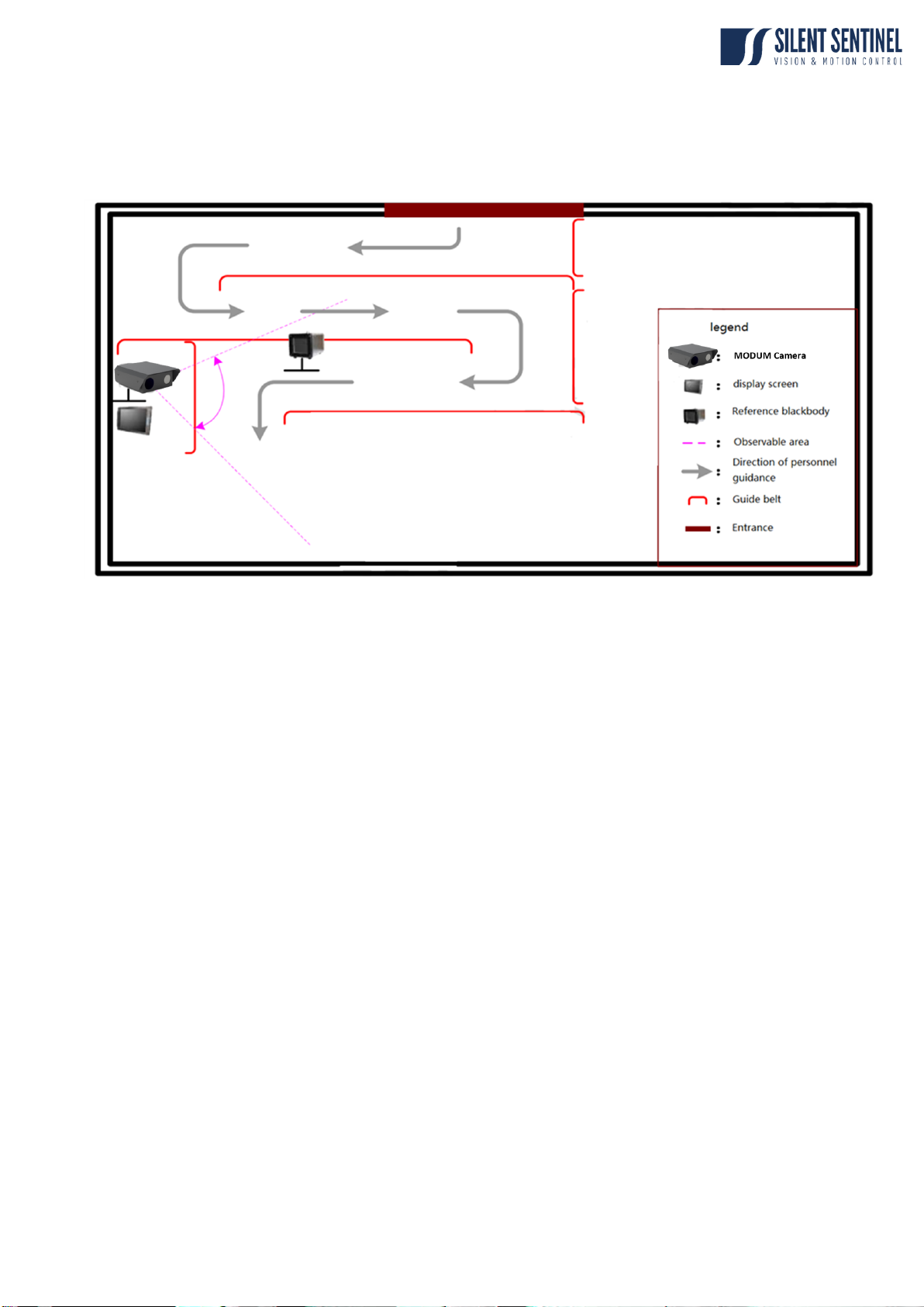
Typical Deployment Scenario
The below architecture outlines a typical deployment scenario
Notes:
Personnel Movement
The above deployment includes a forced chanell that the individuals have to walk through. This
ensures a compliant pose when walking towards the camera. It also provides time for the individuals
skin temperature to stabilize versus the internal temperature and reduce the impact brought about
by the outside environment.
Camera Placement
The Camera / Guide Belt placement ensures personnel cannot get ‘too close’ to the cameras. Any
measurements away from the set range (typically 2m) will become less accurate. If they are
measured further away, the read temperature will be lower. If they are measured closer the read
temperature will be higher (potentially leading to false alarms).
This manual suits for next models
1
Table of contents
Other Silent Sentinel Camera Accessories manuals


