Silex technology SX-590 Service manual
WA104650XF
SX-590
Embedded Intelligent Module
with Evaluation Board
Developer’s eference

Copyright © 2017 Silex Technology, Inc. All rights reserved.
Jan ary, 2020
Silex Technology, Inc. SPECIFICALLY DISCLAIMS THE IMPLIED WARRANTIES OF MERCHANTABILITY AND FITNESS
OF THIS PRODUCT FOR A PARTICULAR PURPOSE. Silex shall not be liable for any errors contained in this man al or
for any damages res lting from loss of se, data, profits, or any incidental or conseq ential damages arising from the se of
SILEX prod cts or services. The information contained in this doc mentation is s bject to change witho t notice.
Information and descriptions contained herein are the property of Silex. S ch information and descriptions may not be
copied, disseminated, or distrib ted witho t the express written consent of Silex. This p blication is s bject to change
witho t notice.
[IMPORTANT NOTICE]
This prod ct s pports IEEE802.11d based World Wide settings. As this f nction makes slave devices (i.e. yo r prod ct with
this prod ct embedded in) refer to master device’s co ntry code setting beacon, sho ld the co ntry code of the master
device have been set wrongly, the slave devices co ld generate illegal signals accordingly. For this reason, we recommend
that yo sho ld not activate the World Wide settings.
SHOULD YOU REQUIRE AND ACTIVATE THE WORLD WIDE SETTINGS, HOWEVER, IT IS YOUR RESPONSIBILITY
TO ENSURE THAT YOUR PRODUCTS CONFORM TO ALL APPLICABLE LAWS OR REGULATIONS. ANY LAW OR
REGULATION VIOLATION CAUSED BY THE WORLD WIDE SETTINGS OR ANY DAMAGES TO YOU OR YOUR
CUSTOMERS CAUSED BY THE WORLD WIDE SETTINGS WILL BE YOUR RESPONSIBILITY TO SOLVE AND BE AT
YOUR COST, AND WE WILL NOT BE RESPONSIBLE IN ANY WAY. YOU WILL ALSO INDEMNIFY US FROM ANY
DAMAGES, EXPENSES AND COSTS (INCLUDING REASONABLE ATTORNEY FEES) INCURRED BY US ARISING OUT
OF YOUR ACTIVATING THE WORLD WIDE SETTINGS.
This prod ct contains software programs licensed nder GPL (GNU General P blic License) and/or LGPL (GNU Lesser
General P blic License).
Silex Technology, Inc. will provide the so rce code s bject to GPL/LGPL software nder terms and conditions of GPL/LGPL
to individ als or gro ps at their own cost by distrib ting a media s ch CD-ROM, etc. for a period of at least 3 years after the
date of p rchase pon written req est. Please send the req est to the email address below.
Email address
* For the so rce code, please contact s at the above email address
in either Japanese or English.
For details on license information of GPL and LGPL, see below website:
https://www.silex.jp/prod cts/license/index.html
Trademarks
All company or prod ct names referenced in this doc ment may be trademarks or registered trademarks of their respective
owners.
Silex Technology, Inc.
www.silex.jp

Contents
Abo t This Reference G ide........................................................................................................................................................ 1
Safety Preca tions................................................................................................................................................................... 1
Emissions Disclaimer............................................................................................................................................................... 1
Chapter 1 Introd ction................................................................................................................................................................. 2
Notes on Using the SX-590 Mod le WWR Model....................................................................................................................3
Chapter 2 Installing the Eval ation Da ghtercard........................................................................................................................ 4
Verify Development Kit Contents............................................................................................................................................. 6
Connecting the Eval ation Da ghtercard to PC.......................................................................................................................6
Monitoring Mod le Stat s........................................................................................................................................................ 7
OEM Interface.......................................................................................................................................................................... 7
Electrical Characteristics.......................................................................................................................................................... 8
Power Inp t.......................................................................................................................................................................... 8
Serial Ports........................................................................................................................................................................... 9
RS-232 Cable..................................................................................................................................................................... 10
Using the GPIO Special F nctions..................................................................................................................................... 11
I/O Header.......................................................................................................................................................................... 11
USB Host Port.................................................................................................................................................................... 13
Ethernet Port...................................................................................................................................................................... 13
Additional OEM Interface Signals....................................................................................................................................... 13
Serial Peripheral Interface.................................................................................................................................................. 13
OEM Interface Electrical Characteristics............................................................................................................................ 14
Chapter 3 Config ring the SX-590............................................................................................................................................. 15
Basic Config ration Req irements......................................................................................................................................... 15
Initial Wireless Set p.............................................................................................................................................................. 16
Config ration Methods........................................................................................................................................................... 17
Using a Web Browser to Config re the SX-590..................................................................................................................... 17
Using AMC Manager® to Config re the SX-590....................................................................................................................22
Using the Internal Command Console to Config re the SX-590............................................................................................24
Chapter 4 Using the SX-590 with Yo r Application.................................................................................................................... 26
Lin x Programmability............................................................................................................................................................ 27
C stomizing the SX-590 User Interface................................................................................................................................. 28
Raw TCP connection............................................................................................................................................................. 29
RFC 2217 Remote Modem Control S pport..........................................................................................................................30
Server Certificate................................................................................................................................................................... 31
ECable Mode......................................................................................................................................................................... 33
Print Server Mode.................................................................................................................................................................. 35
Console Mode Switching........................................................................................................................................................ 36
Access Point Mode................................................................................................................................................................ 37
Bridge Mode........................................................................................................................................................................... 40
Smart Wireless Set p............................................................................................................................................................ 43
Fast BSS Transition............................................................................................................................................................... 48
Chapter 5 Interfacing the SX-590 to the OEM Device............................................................................................................... 50
OEM Interface........................................................................................................................................................................ 57
Installing the SX-590.............................................................................................................................................................. 58
Antenna Connectors.............................................................................................................................................................. 59

General P rpose I/O Interface............................................................................................................................................... 59
Chapter 6 Advanced Config ration............................................................................................................................................ 60
Factory Defa lt Settings......................................................................................................................................................... 60
Restoring Factory Defa lt Settings..................................................................................................................................... 61
Modifying TCP/IP Settings..................................................................................................................................................... 61
Changing CPU Operation Mode............................................................................................................................................. 63
Config ring the General P rpose I/O (GPIO) Lines...............................................................................................................64
Chapter 7 Prod ct Specifications............................................................................................................................................... 69
TCP Port Connections........................................................................................................................................................... 71
Appendix A Wireless Sec rity Config ration.............................................................................................................................. 72
Appendix B Console Commands............................................................................................................................................... 76
1. Introd ction and command console access information..................................................................................................... 76
2. Network Commands........................................................................................................................................................... 77
2.1 SET NW WIRED.......................................................................................................................................................... 77
2.2 SH NW.......................................................................................................................................................................... 77
2.3 SET NW CHannel......................................................................................................................................................... 78
2.4 SET NW MOde............................................................................................................................................................. 78
2.5 SET NW RADio............................................................................................................................................................ 78
2.6 SH NW RATE............................................................................................................................................................... 79
2.7 SET NW RTS............................................................................................................................................................... 79
2.8 SH NW SQ................................................................................................................................................................... 79
2.9 SET NW SSid............................................................................................................................................................... 80
2.10 SET NW STEALTHssid.............................................................................................................................................. 80
2.11 SET NW START......................................................................................................................................................... 80
2.12 SH NW MAC............................................................................................................................................................... 80
2.13 SH NW PROFILE....................................................................................................................................................... 80
2.14 SEt NW PROFCFG.................................................................................................................................................... 81
2.15 SEt NW PROFACT..................................................................................................................................................... 81
2.16 SH NW WLLIST.......................................................................................................................................................... 81
3. Wireless Network Sec rity Commands.............................................................................................................................. 82
3.1 SET NW AUTHtype...................................................................................................................................................... 82
3.2 DEL NW CERTS.......................................................................................................................................................... 82
3.3 SET NW ENC............................................................................................................................................................... 82
3.4 SET NW KEY#............................................................................................................................................................. 83
3.5 SET NW KEYNUM....................................................................................................................................................... 83
3.6 SET NW KEYVAL......................................................................................................................................................... 83
3.7 SET NW WPAPSK....................................................................................................................................................... 83
3.8 SET NW ID................................................................................................................................................................... 83
3.9 SET NW PW................................................................................................................................................................. 84
3.10 SET NW ANONID....................................................................................................................................................... 84
3.11 SET NW PEAPGTC.................................................................................................................................................... 84
3.12 SET NW PEAPMSchap.............................................................................................................................................. 84
3.13 SET NW PEAPV0....................................................................................................................................................... 85
3.14 SET NW PKPASS...................................................................................................................................................... 85
3.15 SET NW CACERT...................................................................................................................................................... 85
3.16 SET NW CLCERT...................................................................................................................................................... 85
3.17 SET NW CLKEY......................................................................................................................................................... 85
3.18 SET NW SSCCITY..................................................................................................................................................... 86

3.19 SET NW SSCCOMNAME........................................................................................................................................... 86
3.20 SET NW SSCCOUNTRY............................................................................................................................................ 86
3.21 SET NW SSCKEYSIZE.............................................................................................................................................. 86
3.22 SET NW SSCORGNAME........................................................................................................................................... 87
3.23 SET NW SSCORGUNIT............................................................................................................................................. 87
3.24 SET NW SSCSTATE.................................................................................................................................................. 87
3.25 SET NW SSCGEN..................................................................................................................................................... 87
4. Wireless Network Roaming Control................................................................................................................................... 88
4.1 SET NW BGSCAN....................................................................................................................................................... 88
4.2 SET NW FTOTA........................................................................................................................................................... 88
4.3 SET RM........................................................................................................................................................................ 88
4.4 SET RM SCAN NORM................................................................................................................................................. 88
4.5 SET RM THRESH CRITical.......................................................................................................................................... 89
5. Wireless to Ethernet Client Bridging Config ration............................................................................................................90
5.1 SET NW BRACCess.................................................................................................................................................... 90
5.2 SET NW BRCLADDR................................................................................................................................................... 90
5.3 SET NW BRIDGE......................................................................................................................................................... 90
5.4 SH NW BRIDGE........................................................................................................................................................... 91
5.5 SET NW BRSTATIC..................................................................................................................................................... 91
5.6 SH NW BRFILTER....................................................................................................................................................... 91
5.7 SET NW BRFILTER..................................................................................................................................................... 91
5.8 SET NW BRFILTERADDR........................................................................................................................................... 92
5.9 SH NW BRFILTERADDR............................................................................................................................................. 92
6. Smart Wireless Set p........................................................................................................................................................ 93
6.1 Smart Wireless Set p for station.................................................................................................................................. 93
6.1.1 SET NW SWSPINCODE........................................................................................................................................ 93
6.1.2 SET NW SWSPBC................................................................................................................................................. 93
6.1.3 SET NW SWSPBC NOWAIT................................................................................................................................. 93
6.1.4 SET NW SWSPIN.................................................................................................................................................. 93
6.2 Smart Wireless Set p for AP........................................................................................................................................ 94
6.2.1 SET NW SWSPINCODE........................................................................................................................................ 94
6.2.2 SET NW APSWSPBC............................................................................................................................................ 94
6.2.3 SET NW APSWSPBC NOWAIT............................................................................................................................. 94
6.2.4 SET NW APSWSPIN............................................................................................................................................. 94
6.2.5 SET NW APSWSCCAncel..................................................................................................................................... 94
6.2.6 SH NW APSWSCSTat s....................................................................................................................................... 94
7. Port Commands................................................................................................................................................................. 95
7.1 Serial Port Commands.................................................................................................................................................. 95
7.1.1 SH PORT............................................................................................................................................................... 95
7.1.2 SET PORT S1 CH.................................................................................................................................................. 95
7.1.3 SET PORT S2 COnsole......................................................................................................................................... 95
7.1.4 SET PORT S1 CONSTR........................................................................................................................................ 96
7.1.5 SH PORT S1 CONSTR.......................................................................................................................................... 96
7.1.6 SET PORT S1 DTR............................................................................................................................................... 97
7.1.7 SET PORT S1 FLOW............................................................................................................................................ 97
7.1.8 CLEAR PORT S1 JOB........................................................................................................................................... 97
7.1.9 SET PORT S1 LATENCY...................................................................................................................................... 97

7.1.10 SET PORT S1 PARITY........................................................................................................................................ 98
7.1.11 SET PORT S1 SPeed.......................................................................................................................................... 98
7.1.12 SH PORT S1 STAt s........................................................................................................................................... 98
7.1.13 SET PORT S1 STOP........................................................................................................................................... 98
7.2 ECable Port Commands............................................................................................................................................... 99
7.2.1 SET PORT S1 ECABLE......................................................................................................................................... 99
7.2.2 SH PORT S1 ECABLE........................................................................................................................................... 99
7.2.3 SET PORT S1 ECADDR........................................................................................................................................ 99
7.2.4 SET PORT S1 ECCONN....................................................................................................................................... 99
7.2.5 SET PORT S1 ECLPORT.................................................................................................................................... 100
7.2.6 SET PORT S1 ECNHOST................................................................................................................................... 100
7.2.7 SET PORT S1 ECPORT...................................................................................................................................... 100
7.2.8 SET PORT S1 ECRADDR................................................................................................................................... 100
7.2.9 SET PORT S1 ECRPORT................................................................................................................................... 101
7.2.10 SET PORT S1 ECENCRYPT............................................................................................................................. 101
7.2.11 SET PORT S1 ECTMMSEC.............................................................................................................................. 101
7.2.12 SET PORT S1 ECUDP...................................................................................................................................... 101
7.3 SH SERVEr QUE e................................................................................................................................................ 101
8. Server Information Commands........................................................................................................................................ 102
8.1 SH SERIAL................................................................................................................................................................. 102
8.2 SH SERVEr................................................................................................................................................................ 102
8.3 SH SERVEr CO.......................................................................................................................................................... 102
8.4 SET SERVEr DEscription........................................................................................................................................... 103
8.5 SH SERVEr FWVER.................................................................................................................................................. 103
8.6 SH SERVEr MODEL.................................................................................................................................................. 103
8.7 SET SERVEr NAme................................................................................................................................................... 103
8.8 SH SERVEr STAtistics............................................................................................................................................... 104
8.9 SH SNMP................................................................................................................................................................... 104
8.10 SET SNMP CONtact................................................................................................................................................. 104
8.11 SET SNMP GETCOMM............................................................................................................................................ 104
8.12 SET SNMP LOCation............................................................................................................................................... 105
8.13 SET SNMP SETCOMM2.......................................................................................................................................... 105
8.14 SH VErsion............................................................................................................................................................... 105
9. Service Commands.......................................................................................................................................................... 106
9.1 SH SERVI................................................................................................................................................................... 106
9.2 SET SERVI <service name> BOT.............................................................................................................................. 106
9.3 SET SERVI <service name> EOT.............................................................................................................................. 106
9.4 SH SERVI STRings [string_n m]............................................................................................................................... 107
9.5 SET SERVI <service name> FIlter............................................................................................................................. 107
9.6 SH SERVI FILters....................................................................................................................................................... 107
9.7 SET SERVI <service name> FMS.............................................................................................................................. 107
9.8 SET SERVI <service name> FRS.............................................................................................................................. 108
9.9 SET SERVI <service name> IP.................................................................................................................................. 108
9.10 SET SERVI <service name> NAme......................................................................................................................... 108
9.11 SET SERVI <service name> POrt............................................................................................................................ 108
9.12 SET SERVI <service name> PRIority....................................................................................................................... 108
9.13 SH SERVI PRI [service_n m]................................................................................................................................... 109
9.14 SET SERVI <service name> QUE e........................................................................................................................ 109

9.15 SET SERVI <service name> RECeive.....................................................................................................................109
9.16 SET SERVI <service name> TCP............................................................................................................................ 109
9.17 SET SERVI <service name> ENCrypt...................................................................................................................... 109
9.18 SH SERVI SUMmary [service_n m]......................................................................................................................... 110
10. String Commands.......................................................................................................................................................... 111
10.1 SET STRing.............................................................................................................................................................. 111
10.2 CL STRing................................................................................................................................................................ 111
10.3 SH STRing [string_n m]........................................................................................................................................... 111
10.4 SH FILters................................................................................................................................................................ 112
11. TCP/IP Commands........................................................................................................................................................ 113
11.1 SH IP........................................................................................................................................................................ 113
11.2 SET IP ACcess......................................................................................................................................................... 113
11.3 SET IP MEthod......................................................................................................................................................... 114
11.4 SET IP ADdress....................................................................................................................................................... 114
11.5 SET IP SUbnet......................................................................................................................................................... 114
11.6 SET IP RO ter.......................................................................................................................................................... 114
11.7 SET IP BOot............................................................................................................................................................. 115
11.8 SET IP KEepalive..................................................................................................................................................... 115
11.9 SET IP HTTP............................................................................................................................................................ 115
11.10 SET IP HTTPS....................................................................................................................................................... 115
11.11 SET IP TFTP.......................................................................................................................................................... 115
11.12 SET IP NTP............................................................................................................................................................ 116
11.13 SET IP TCP............................................................................................................................................................ 116
11.14 SET IP LPD............................................................................................................................................................ 116
11.15 SET IP TELnet........................................................................................................................................................ 116
11.16 SET IP SX_INTERN............................................................................................................................................... 116
11.17 SET IP SSH............................................................................................................................................................ 116
11.18 SET IP PRObe....................................................................................................................................................... 117
11.19 SET IP TImeo t...................................................................................................................................................... 117
11.20 SET IP FTIme......................................................................................................................................................... 117
11.21 SET IP REtry.......................................................................................................................................................... 117
11.22 SET IP STAT s...................................................................................................................................................... 117
11.23 SET IP WIndow...................................................................................................................................................... 118
11.24 SET IP BAnner....................................................................................................................................................... 118
12. DNS Commands............................................................................................................................................................ 119
12.1 SH DNS.................................................................................................................................................................... 119
12.2 SET DNS DOMain.................................................................................................................................................... 119
12.3 SET DNS PRImary................................................................................................................................................... 119
12.4 SET DNS SECondary............................................................................................................................................... 119
13. DHCP Server Commands.............................................................................................................................................. 120
13.1 SET DHCPS............................................................................................................................................................. 120
13.2 SH DHCPS............................................................................................................................................................... 120
13.3 SET DHCPS Address............................................................................................................................................... 120
13.4 SET DHCPS SUbnet................................................................................................................................................ 120
13.5 SET DHCPS RO ter................................................................................................................................................. 120
13.6 SET DHCPS LEase.................................................................................................................................................. 121
14. NTP Command.............................................................................................................................................................. 122

14.1 SET NTP SERVER................................................................................................................................................... 122
14.2 SH NTP DATE.......................................................................................................................................................... 122
15. TLS Commands............................................................................................................................................................. 123
15.1 SET APPTLS CACFGCERT..................................................................................................................................... 123
15.2 SET APPTLS CLCERT............................................................................................................................................. 123
15.3 SET APPTLS CLKEY............................................................................................................................................... 123
15.4 SET APPTLS CLPKPASS........................................................................................................................................ 123
15.5 DEL APPTLS............................................................................................................................................................ 123
15.6 SH APPTLS.............................................................................................................................................................. 124
16. GPIO Control.................................................................................................................................................................. 125
16.1 SET GPIO DIR......................................................................................................................................................... 125
16.2 SH GPIO DIR........................................................................................................................................................... 125
16.3 SET GPIO DIRM...................................................................................................................................................... 126
16.4 SH GPIO DIRM........................................................................................................................................................ 126
16.5 SET GPIO SPECial.................................................................................................................................................. 126
16.6 SH GPIO SPECial.................................................................................................................................................... 127
16.7 SET GPIO SPECM................................................................................................................................................... 127
16.8 SHow GPIO SPECM................................................................................................................................................ 127
16.9 SET GPIO DATA...................................................................................................................................................... 128
16.10 SHow GPIO DATA.................................................................................................................................................. 128
17. Firmware Update............................................................................................................................................................ 129
17.1 SET LOAd XModem................................................................................................................................................. 129
18. Power Management....................................................................................................................................................... 130
18.1 SET NW WLIF.......................................................................................................................................................... 130
18.2 SET POWER LEVEL................................................................................................................................................ 130
18.3 SET POWER CPUFREQ.......................................................................................................................................... 130
19. Other Commands........................................................................................................................................................... 131
19.1 SET DEFAULT......................................................................................................................................................... 131
19.2 EXIT.......................................................................................................................................................................... 131
19.3 HElp <command>..................................................................................................................................................... 131
19.4 INIT........................................................................................................................................................................... 131
19.5 SET PAssword......................................................................................................................................................... 132
19.6 SAVE........................................................................................................................................................................ 132
20. Compatibility with Existing Models................................................................................................................................. 133
20.1 SET NW DISCONN.................................................................................................................................................. 133
20.2 SET RM SCAN LOW................................................................................................................................................ 133
20.3 SET RM THRESH LOW........................................................................................................................................... 133
Appendix C SX-590 Antenna Information................................................................................................................................ 134
Antenna Specifications......................................................................................................................................................... 134
Appendix D Firmware Update Proced res............................................................................................................................... 135
Appendix E GNU/Lin x Open So rce and Programming........................................................................................................137
Appendix F Silex Contact Information...................................................................................................................................... 138
Figures
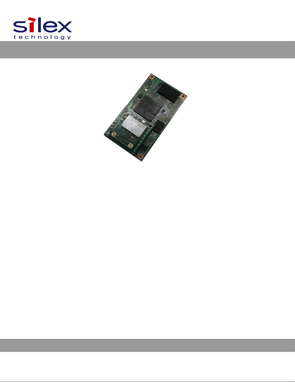
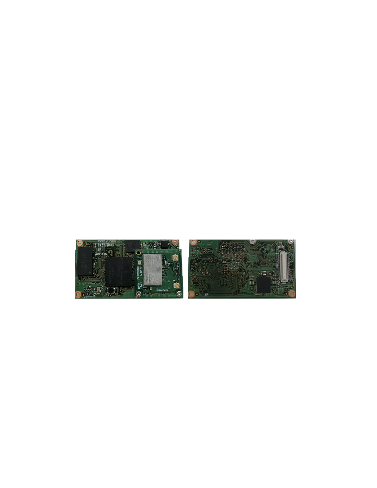
Fig re 1 SX-590 top and bottom view.......................................................................................................................................... 2

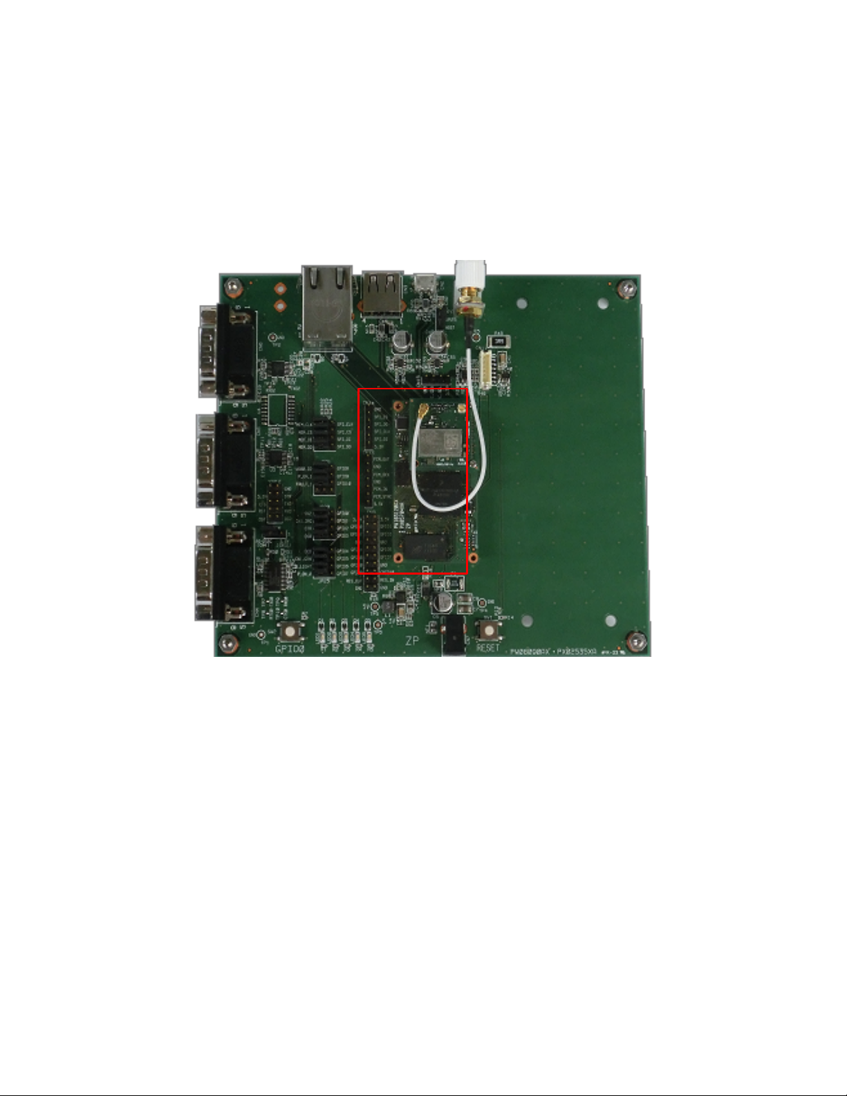
Fig re 2 SX-590 Mod le in Eval ation Da ghtercard.................................................................................................................. 4
Fig re 3 Major connectors in Eval ation Da ghtercard...............................................................................................................5
Fig re 4 GPIO Special F nctions J mpers (Example Config ration)........................................................................................11
Fig re 5 TCP/IP Config ration Window..................................................................................................................................... 32
Fig re 6 I/O Port Config ration Window.................................................................................................................................... 33
Fig re 7 Using spacers with SX-590 WLAN model....................................................................................................................58
Fig re 8 TCP/IP Config ration Window..................................................................................................................................... 61
Fig re 9 Password Config ration Window................................................................................................................................. 62
Fig re 10 System Config ration Window................................................................................................................................... 63
Tables
Table 1 S pported E ropean Co ntries...................................................................................................................................... 3
Table 2 Development Kit Contents.............................................................................................................................................. 6
Table 3 Stat s Monitors............................................................................................................................................................... 7
Table 4 OEM Interface Pino t...................................................................................................................................................... 7
Table 5 DB-9 Pino ts for RS-232 Mode...................................................................................................................................... 9
Table 6 Logical Serial Port 1 (CN10) Signal Descriptions............................................................................................................9
Table 7 RS-232 Cable Pino t Description................................................................................................................................. 10
Table 8 GPIO Special F nctions................................................................................................................................................ 11
Table 9 I/O Header.................................................................................................................................................................... 12
Table 10 General P rpose I/O Signal Descriptions...................................................................................................................13
Table 11 OEM Signal Parameter Descriptions.......................................................................................................................... 14
Table 12 Self Signed Certificate................................................................................................................................................ 31
Table 13 OEM Interface Pino t.................................................................................................................................................. 57
Table 14 GPIO Interface............................................................................................................................................................ 59
Table 15 Factory Defa lt Settings.............................................................................................................................................. 60
Table 16 TCP/IP Settings.......................................................................................................................................................... 62
Table 17 GPIO General Commands.......................................................................................................................................... 65
Table 18 GPIO Data Commands............................................................................................................................................... 68
Table 19 Prod ct Specifications................................................................................................................................................ 69
Table 20 Radio Specifications................................................................................................................................................... 69

Table 21 TCP Port Connections................................................................................................................................................ 71
Table 22 List of sec rity settings can be config red from the web.............................................................................................72
Table 23 Console AUTH parameter and corresponding web config ration...............................................................................73
Table 24 Console ENC parameter and corresponding web config ration.................................................................................73
Table 25 SX-590 Antenna Electrical Specifications................................................................................................................. 134

About This Reference Guide
This reference g ide provides detailed specifications, diagrams and additional information req ired to integrate
the SX-590 embedded intelligent mod le in a prod ct. The intended a diences are the developers and engineers
responsible for the integration of the mod le in another prod ct.
Safety recautions
•To prevent damage to the SX-590 mod le’s electronic circ it components, follow established ESD
practices and proced res for handling static-sensitive devices. All ESD-sensitive components m st be
stored and shipped in ESD-cond ctive bags or b bble-wrap and labeled as s ch sing the
standardized ESD adhesive warning label.
•Ethernet electrical wiring m st be at least 6 feet from bare power wiring or lightning rods and associated
wires, and at least 6 inches from other types of wire (antenna wires, doorbell wires, wires from
transformers to neon signs), steam or hot water pipes, and heating devices.
•Protectors and gro nding wire placed by the service provider m st not be connected to, removed, or
modified by the c stomer.
Emissions Disclaimer
Final emission certification per FCC, CE and other agency req irements are the responsibility of the OEM sing
any printed circ it assemblies or other items described in this developer’s kit in their packaged prod ct.
1
Chapter 1
Introduction
The SX-590 embedded intelligent mod le provides a complete sol tion for integrating wireless networking
technology into virt ally any OEM prod ct that has an RS-232 or UART serial port. It has a main printed circ it
board that contains a processor, memory, flash memory, three (3) serial ports (one dedicated for se as a
console) pl s a USB V2.0 host port and an SPI port.
D al 2.4GHz/5GHz operation is s pported and the dimension is 55.0 x 30.0 x 11.0 mm.
The SX-590-6900 Eval ation Da ghtercard is available to expedite the development process. This board
incl des an RJ45 Ethernet connector, three 9-pin serial connectors, one USB connector, header connectors for all
major I/O, power s pply, antenna, cables, and software.
Figure 1 SX-590 top and bottom view
2

Notes on Using the SX-590 Module WWR Model
The SX-590 Mod le WWR Model config res its co ntry code setting sing the radio waves from adjacent Access
Points. Once the co ntry setting is config red, it is not changed nless the SX-590 mod le is restarted.
Also, it is impossible to se the Access Point feat re for the SX-590 Mod le WWR Model. To se the SX-590
mod le as Access Point, the co ntry code setting needs to be changed.
For details on how to change the co ntry code setting, please contact Silex Technology.
The SX-590 Mod le WWR Model s pports 4 regions; Japan, United States, Canada and E rope.
If the co ntry code information of following E ropean co ntries is retrieved from the adjacent Access Points, the
SX-590 mod le config res its co ntry code to E rope.
Table 1 Supported European Countries
Belgi m Greece Lith ania Port gal
B lgaria Spain L xembo rg Romania
Czech Rep blic France H ngary Slovenia
Denmark Croatia Malta Slovakia
Germany Italy Netherlands Finland
Estonia Cypr s A stria Sweden
Ireland Latvia Poland United Kingdom
Iceland Norway Liechtenstein Switzerland
3
IM ORTANT:
- The SX-590 Module WWR Model cannot be used in the United States due to the FCC regulations.
- If the country code setting is not configured, the SX-590 Module WWR Model does not emit radio waves. When there is
no Access oint that emits radio waves including the country code information, the wireless feature of the SX-590
module cannot be used.
IM ORTANT:
Silex Technology guarantees proper operation of the SX-590 module and its compliance with local radio law only when
the configured country code information is one of above countries and the SX-590 module actually exists in that country.
Chapter 2
Installing the Evaluation Daughtercard
The SX-590-6900 Eval ation Da ghtercard is designed to help yo in the development of the necessary
hardware and software req ired to se the SX-590 mod le. It incl des I/O connectors, cables, and power s pply
in an easy-to- se package. The SX-590 Mod le is installed in the Eval ation Da ghtercard as shown in Fig re 2.
Figure 2 SX-590 Module in Evaluation Daughtercard
The Eval ation Da ghtercard makes it easy to connect to the SX-590 for test and development by providing the
following:
Three 9-pin connectors (CN4,5,6) and one 10-pin header (CN12) for connecting the SX-590 serial ports
One 20-pin header for connecting GPIO's, power and gro nd (CN8)
One RJ45 Ethernet connector (CN1)
One power jack (CN7)
2 LEDs for displaying the power and network stat s (LED6,7)
5 LEDs for monitoring the GPIO signals (LED1,2,3,4,5)
One Test B tton for printing config ration data and resetting the nit to factory defa lts (SW2)
4
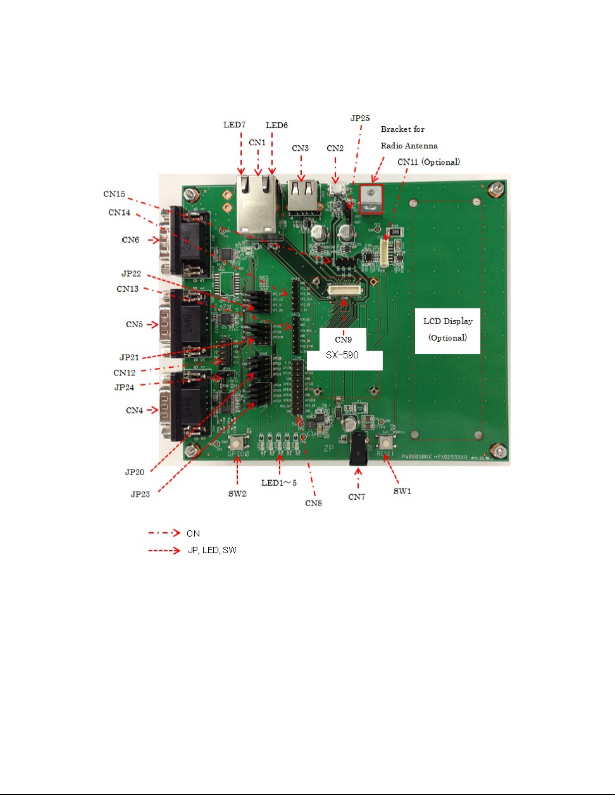
Three 12-pin header (JP20,21,23) for selecting GPIOs and one 12-pin header (JP22) for selecting SPIs.
The locations of the major Eval ation Da ghtercard connectors and headers are shown in the diagram below.
Figure 3 Major connectors in Evaluation Daughtercard
5

Verify Development Kit Contents
The SX-590 Eval ation Mod le Development Kit consists of the components listed in Table 2. Please ens re that
all materials listed are present and free from visible damage or defects before proceeding. If anything appears to
be missing or damaged, please contact Silex.
Table 2 Development Kit Contents
Description
EVK Board
SX-590
D al band Antenna
Power s pply
RS232 cross cable
LAN cable
USB cable
Connecting the Evaluation Daughtercard to C
To connect the SX-590-6900 Eval ation Da ghtercard to yo r PC:
1. Connect one serial n ll-modem cable from the Serial Port (CN6) DB-9 connector on the Eval ation
Da ghtercard to a serial port on a personal comp ter or laptop (the comp ter’s serial port m st be set to
115.2Kbps, no parity, no flow control, and 8-bit character size). The PC or laptop acts as a console port for
command line config ration and monitoring. (CN6 is the Lin x console which provides access to the on board
Lin x system, while CN5 is connected to the config ration application, and is connected to the console
config ration task. Lin x f nctions are not available from CN5.)
2. If yo want to se an Ethernet LAN connection for the initial config ration of the SX-590, pl g a category 5 Ethernet
cable into the RJ-45 jack. The Ethernet interface has A to-MDI/MDIX that a tomatically detects and config res itself
for either a straight-thr or crossover Ethernet cable.
6

Monitoring Module Status
Yo can monitor the mod le stat s sing the Stat s LED (Orange) on the Eval ation Da ghtercard.
Table 3 defines the defa lt f nctions of the LED stat s indicators.
Table 3 Status Monitors
Function State Status
Stat s LED On The network connection is active (wired/wireless).
Off The network connection is not active.
Blinking Firmware pdate is in progress (Important: Do not power off
the module during the update process)
OEM Interface
The OEM interface is a 50-pin header (CN9) that is sed to connect the SX-590 mod le to the SX-590-6900 Eval ation
Da ghtercard. It will also serve as the primary means of comm nications between the SX-590 and yo r OEM device
(refer to Chapter 5 Interfacing the SX-590 to the OEM Device for information on sing this header to connect with yo r
device).
Table 4 shows the OEM interface pino t for the Eval ation Da ghtercard. Please note that the OEM interface
signals are not directly accessible from the OEM header when the Eval ation Da ghtercard is sed. Rather,
these signals are available thro gh convenient connectors on the Eval ation Da ghtercard, s ch as the CN8,
CN12, CN13, CN14, CN15 and the 9-pin serial connectors. These connectors are described later in this chapter.
All inp t and o tp t signals, except the differential signals, are 0 to 3.3 V logic signals.
Table 4 OEM Interface inout
IN SIGNAL Attrib. Buffer IN SIGNAL Attrib. Buffer
1 +5.0V +5.0V Power 2 +5.0V +5.0V Power
3 +5.0V +5.0V Power 4 GPIO0/Switch I/O(PU) LVTTL
5 RESET I(PU) LVTTL 6 RESETOUT O(PD) LVTTL
7 GND GND Power 8 GND GND Power
9 USB1-DP I/O USB 10 USB2-DN I/O USB
11 USB1-DN I/O USB 12 USB2-DP I/O USB
13 GND GND Power 14 GND GND Power
15 PCM_IN I LVTTL 16 PCM_OUT O LVTTL
17 PCM_BCK I/O LVTTL 18 GPIO1 I/O(PU) LVTTL
19 PCM_SYNC I/O LVTTL 20 GPIO3 I/O(PU) LVTTL
21 GPIO2 I/O(PU) LVTTL 22 GPIO5 I/O(PU) LVTTL
23 GPIO4 I/O(PU) LVTTL 24 GPIO7 I/O(PU) LVTTL
7

IN SIGNAL Attrib. Buffer IN SIGNAL Attrib. Buffer
25 GPIO6 I/O(PU) LVTTL 26 GND GND Power
27 GPIO8 I/O(PU) LVTTL 28 UART2_TX O LVTTL
29 GPIO9 I/O(PU) LVTTL 30 UART2_CTS I(PU) LVTTL
31 UART3_TX O LVTTL 32 UART2_RTS O LVTTL
33 UART3_RX I(PU) LVTTL 34 UART2_RX I(PU) LVTTL
35 GPIO11 I/O LVTTL 36 UART1_TX O LVTTL
37 GPIO12 I(PU) LVTTL 38 UART1_RX I(PU) LVTTL
39 GPIO13 I/O LVTTL 40 2C_SCL I/O(PU) I2C
41 GPIO14 I/O LVTTL 42 I2C_SDA I/O(PU) I2C
43 GND GND Power 44 GND GND Power
45 LAN_TX_P O LAN 46 LAN_RX_P I LAN
47 LAN_TX_M O LAN 48 LAN_RX_M I LAN
49 LAN_CT O LVTTL 50 GPIO10 I/O(PU) LVTTL
Electrical Characteristics
The power req irements, port pino ts, GPIO characteristics, cable connections and wireless operational modes
are described below.
ower Input
Power to the SX-590 Mod le and the SX-590-6900 Eval ation Da ghtercard is s pplied thro gh the power jack,
located at CN7, at 5V±5%. Use the incl ded power s pply.
8
NOTE:
I( U), O( U), I/O( U): ull up with 3.3V 10kΩ to SX-590 side
O( D): ull down with 3.3V 10kΩ to SX-590 side

Serial orts
Standard serial RS-232 signals are available on the DB-9 male connectors CN4, CN5 and CN6 for Serial Ports 1,
2 and 3 (Serial Port 3 is the Lin x console which provides access to the on board Lin x system, while Serial Port
2 is connected to the config ration application, and is connected to the console config ration task. Lin x f nctions
are not available from Serial Port 2.) Serial Port 1 incl des the RTS and CTS modem signals for hardware flow
control, and can also s pport DCD, DTR, and DSR by setting the appropriate j mpers on the JP20 and JP23
header (see the Using the GPIO Special Functions section later in this chapter). Serial Port 3 does not s pport
any modem signals, and is fixed for operation at 115.2Kbps, no parity, no flow control, and 8-bit character size.
Table 5 DB-9 inouts for RS-232 Mode
DB-9 RS-232 Signal Type
1 DCD Inp t
Enabled via JP23 header (Serial Port 1 only)
2 RXD Inp t
3 TXD O tp t
4 DTR O tp t
Enabled via JP20 header (Serial Port 1 only)
5 Gro nd
6 DSR Inp t
Enabled via JP20 header (Serial Port 1
only)
7 RTS O tp t (S pported on Serial Port 1 only)
8 CTS Inp t (S pported on Serial Port 1 only)
9 NC
Serial Port 1 can also be accessed sing logic signals via a 10-pin header located at CN12. If yo want to se
this header, yo m st place a j mper on 3.3V header (CN12) at JP24 to disable the RS-232 transceiver. The
pino ts are as follows:
Table 6 Logical Serial ort 1 (CN10) Signal Descriptions
in Signal Input/Output in Signal Input/Output
1 DCD Inp t
Enabled via JP24 header
2 DSR Inp t
Enabled via JP24 header
3 RXD Inp t 4 RTS O tp t
5 TXD O tp t 6 CTS Inp t
7 DTR O tp t
Enabled via JP24 header
8 3.3V
9 GND 10 No
Connect
9

All signals are 0 to 3.3 V logic signals.
Note that Serial Port 3 is dedicated for se as Lin x console commands. Serial port 3 is always set for operation
at 115.2Kbps, 8 bit character size, no parity, and no flow control.
Serial Port 2 is set by defa lt for console operation at 115.2Kbps, 8-bit characters, no parity, and no flow control. This port
can be set as a second I/O port sing the SET PORT S2 CONSOLE DISABLE console command.
RS-232 Cable
The s pplied DB-9 female-to-female n ll modem cable is wired as shown below. The pino ts are compatible with
a standard PC 9-pin serial connector, so this cable can be sed to directly connect a PC to Serial Port 3 for se
as a console terminal to config re the SX-590. It can also be sed to connect many types of OEM serial devices
to Serial Port 1 or Serial Port 2, provided that these devices se PC-compatible 9-pin connectors.
Table 7 RS-232 Cable inout Description
in Description
1 DCD (Data Carrier Detect) Inp t*
2 RxD (Receive Data) Inp t
3 TxD (Transmit Data) O tp t
4 DTR (Data Terminal Ready) O tp t*
5 Gro nd
6 DSR (Data Set Ready) Inp t*
7 RTS (Req est To Send) O tp t*
8 CTS (Clear To Send) Inp t*
10
NOTE:
Serial ort 1 (CN4) supports all signals. Serial ort 2 (CN5) and ort 3 (CN6) do not support flow control signals.
Table of contents
Other Silex technology Motherboard manuals


