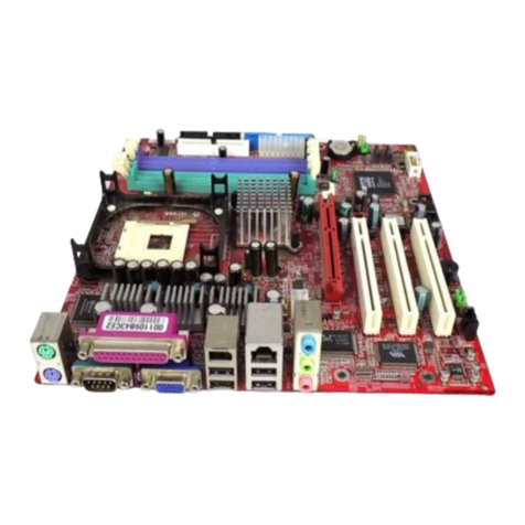
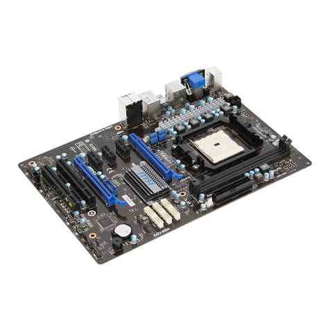
MSI K7 Master MS-6341 User manual

Introduction
1-1
Introduction
The MS-6341 ATX mainboard is a high-performance computer
mainboard based on AMD®761 chipset and VT82C686B. The MS-6341 is
designed for the AMD®Duron & Thunderbird processor for inexpensive
business/personal desktop markets.
The AMD-761 system controller features the AMD Duron system
bus, system memory controller, accelerated graphics port (AGP) controller,
and peripheral component interconnect (PCI) bus controller. The AMD-761
system controller is also designed to support 266-MHz DDR SDRAM
DIMMs.
The VT82C686B integrates all system control functions such as ACPI
(Advances Configuration and Power Interface). The ACPI provides more
Energy Saving Features for the OSPM (OS Direct Power Management)
function. The VT82C686B chipset also improves the IDE transfer rate by
supporting Ultra DMA-33/66/100 IDE that transfers data at the rate 33/66/
100MB/sec.
This chapter contains the following topics:
Mainboard Specifications 1-2
Mainboard Layout 1-4
Quick Components Guide 1-5
Key Features 1-6
MSI Special Features 1-7
1

Chapter 1
1-2
Mainboard Specification
CPU
lSocket A for AMD®DuronTM & AthlonTM processor.
lSupport 600MHz, 650MHz, 700MHz or higher processor
Chipset
lAMD®761 chipset. (569 BGA)
- Supports 266MHz High speed, split transaction system bus.
- AGP 4x and PCI Advanced high performance memory controller
- Support 266MHz DDR SDRAM technology
lVIA®VT686Bchipset.(352BGA)
- Enhanced Power Management Features
- Integrated Super I/O (FDC, LPT, COM 1/2, and IR)
- Dual bus Master IDE Ultra DMA33/66
- Integrated Hardware Soundblaster
- Direct Sound AC97 Audio
-ACPI
Clock Generator
l133Mhz clocks are supported. (266MHz Internal System Bus)
Main Memory
lSupport eight memory banks using four 184-pin DDR-DIMM.
lSupporta maximummemory sizeof 4GB.
Slots
lOne AGP(Accelerated Graphics Port) Pro slot.
-AGP 4xmode
lOne CNR(Communication Network Riser) slot.
lFive 32-bit Master PCI Bus slots.
lSupports 3.3v/5v PCI bus Interface.
On-Board IDE
lAn IDE controller on the VIA®VT686B Chipset provides IDE HDD/CD-
ROM with PIO, Bus Master and Ultra DMA 33/66/100 operation modes.
lCan connect up to four IDE devices.
TM

Introduction
1-3
Audio
lChip Integrated
- Direct Sound AC97 Audio
Onboard Ultra 160 SCSI Connector
lAdaptec AIC-7899
-supports high performance 160Mbytes/sec Single Channel Ultra SCSI
-supports Ultra(SE) devices
On-Board Peripherals
lOn-Board Peripherals include:
- 1 floppy port supports 2 FDD with 360K, 720K, 1.2M, 1.44M and 2.
88Mbytes.
- 2 serial ports (COMA + COM B)
- 1 parallel port supports SPP/EPP/ECP mode
- 4 USB ports (2 Rear Connectors/USB Front Pin Header)
-1IrDA connector forSIR/CIR/FIR/ASKIR/HPSIR.
- 1 Audio/Game port
BIOS
lThe mainboard BIOS provides “Plug & Play” BIOS which detects the
peripheral devices and expansion cards of the board automatically.
lThe mainboard provides a Desktop Management Interface(DMI) function
which records your mainboard specifications.
Dimension
lATXFormFactor: 30.5cmx 25.9cm
Mounting
l9 mounting holes.

Chapter 1
1-4
Mainboard Layout
JFP1
FDD
SCSI2
SCSI1
CNR JP1
BIOS
JMDM
SYSFAN
IDE1
JGS1
IDE2
AGP PRO SLOT
PCI Slot 1
PSI Slot 2
PCI Slot 3
PCI Slot 4
PCI Slot 5
AGP Power Supply
CD-IN
AUX_IN
MDM_IN
PS_FAN
Codec
DDR-DIMM 2
DDR-DIMM 3
DDR-DIMM 4
JP5
DDR-DIMM 1
D-LED
CPUFAN
Socket A
ATX
PowerSupply
JKBV1
Top: Mouse
Bottom:
Keyboard
USB
Top: Port1
Bottom: Port2
Top: LPT
Bottom:
COMA
COMB
Top: Midi/
Game Port
Bottom:
Line-Out
Line-in, Mic
BATT
+
JP3
SW1
JWOL1
JBAT1
VT82C686B
Adaptec
7 8 9 9
SCSI3
USB2
JIR1
MSI
SmartD-LED
JP4
AMD761
Chipset
MS-6341 ATX Mainboard

Introduction
1-5
Quick Components Guide
Component Function Reference
DDR-DIMM 1~4 Installing memory modules See p. 2-5~
2
Socket A Installing CPU See p. 2-2~
2
CPUFAN Connecting to CPUFAN See p. 2-19
SYSFAN Connecting to SYSFAN See p. 2-19
ATX Power Supply Installing power suppl See p. 2-8
IDE1& IDE2 Connecting to IDE hard disk drive See p.2-14
FDD Connecting to floppy disk drive See p.2-13
SCSI 1~ SCSI 3 Connecting to SCSI interface See p. 2-20
USB2 Connecting to USB interface See p. 2-13
AGP Pro Slot Installing AGP card See p. 2-25
PCI Slot 1~5 Installing expansion boards See p. 2-25
SW1 Setting CPU FSB frequency See p. 2-4
JFP1 Connecting to cas See p. 2-15
JMDM Connecting to modem card See p. 2-17
JWOL1 Connecting to LAN card See p. 2-17
JGS1 Connecting to power saving switch See p. 2-18
JIR1 Connecting to IrDA infrared modul See p. 2-18
JBAT1 Clearing CMOS data See p. 2-21
JKBV1 Setting keyboard wake-up functi See p. 2-22
JP1 Setting audio onboard See p. 2-22
JP3 Setting CPU core bus rati See p. 2-23
JP4
S i S D LED l
S223

Chapter 1
1-6
Key Features
lMicrosoft®PC99 compliant
lD-LEDTM - 4 LEDs embedded in mainboard
lT.O.P TechTM III - accuately detect components’ temperature
lPC AlertTM III system hardware monitor
lCPU: Socket A for AMD®DuronTM Processor, 700MHz or higher
lFormFactor: ATX,30.5 cmx25.9cm
lClock:133MHz (266MHz InternalSystem Bus)
lChip Integrated Audio: Direct Sound Ac97 Audio
lMemory: 4 DIMM. Max, up to 4GB SDRAM
lLAN Wake up Function
lI/O: 2 serial ports. 1 parallel port, 4 USB ports, 1 floppy port, 1 IrDA
connector, 1 Audio/Game port
lSlot: 1 AGP Pro slot, 1 CNR slot, 5 PCI slots

Introduction
1-7
MSI Special Features
The MSI special features are designed by MSI R&D that can be seen
only in MSI mainboards. The 6341mainboard is equipped with PC AlertTM III ,
T.O.P TechTM III and D-LEDTM.
T.O.P TechTM.
The T.O.P TechTM is a extended sensing device that can 100% accu-
rately detect the CPU’s temeprature. You can know the temperature on BIOS
setup menu. The PC AlertTM also can provide the information.
Current CPU Temp.
Current System Temp.
Current CPUFAN Speed
Current SYSFAN Speed
Vcore
2.5V
3.3V
5V
12V
Item Help
Menu Level >
↑ ↓ → ← Move Enter:Select +/-/PU/PD:Value F10:Save ESC:Exit F1:General Help
F5:Previous Values F6:Fail-safe defaults F7:Optimized Defaults
CPU temperaure on Setup menu
CMOS Setup Utility - Copyright(C) 1984-2000 Award Software
PC Health Status

Chapter 1
1-8
PCAlertTM III
The PC AlertTM III is a utility you can find in the CD-ROM. The utility
is just like your PC doctor that can detect the following PC hardware status
during real time operation:
* monitor CPU & system temperature
* monitor fan speed
* monitor system voltage
* monitor chassis intrusion
If one of the items above is abnormal, the program main screen will be imme-
diately shown on the screen, with the abnormal item highlighted in red. This
will continue to be shown,until user disables warning.

Introduction
1-9
Features:
lNetwork Management
- Monitoring & remote control
lBasic System Utilities
- Scandisk & Defragment to maintain your HDD
l3D Graphics Design
- Enables a more friendly user interface
lSofwareUtilities
- SoftCooler Optimized Cooling
- Doctor Y2K Diagnoses Y2K problems
- BusRacing function adjusts F.S.B under Windows 95/98
- MoSpeed Speeds up your modem transmission

Chapter 1
1-10
The D-LEDTM uses graphic signal display to
help you understand your system. There are 4 LEDs
embedded in the mainboard which provides up to
16 combination of signals to debug system. The 4
LEDs can debug all problems that fail the system,
such as VGA, RAM or other failures. This special feature is very useful for the
overclocking users. The users can use this feature to detect if there are any
problems or failures while doing the overclocking.
D-LEDTM
D-LED Description
System Power ON
- The D-LED will hang here if the processor is damaged or not insta
properly.
Early Chipset Initialization
Memory Detection Test
- Testing onboard memory size. The D-LED will hang if themem
o
module is damaged or not installed properly.
Decompressing BIOS image to RAM for fast booting.
InitializingKeyboard Controller.
Testing VGA BIOS
- This willstartwriting VGA sign-on message to the screen.
Red Green

Introduction
1-11
Processor Initialization
- This will show information regardingthe processor (like brand n
a
system bus, etc…)
Testing RTC (Real Time Clock)
Initializing Video Interface
- This will start detecting CPU clock, checking type of video onbo
a
Then, detect and initialize the video adapter.
BIOS Sign On
- This will start showing information about logo, processor brand
n
etc….
Testing Base and Extended Memory
- Testing base memory from 240K to 640K and extended memor
y
above 1MB using various patterns.
Assign Resources to all ISA.
InitializingHardDriveController
- This will initialize IDE drive and controller.
Initializing Floppy Drive Controller
- This will initializing FloppyDriveand controller.
Boot Attempt
- This will set lowstack andboot via INT 19h.
O
p
erating System Booting

Chapter 1
1-12

Hardware Setup
2-1
Hardware Setup
This chapter provide you with the information about hardware setup
procedures. While doing the installation, be carefu in l holding the compo-
nents and follow the installtion procedures. For some components, if you
install in the wrong orientation, the components will not work properly.
Besides, use a grounded wrist strap before handling computer
components. Static electricity may damage the components.
.
This chapter contains the following topics:
2
Central Processing Unit (CPU) 2-2
Memory Installation 2-5
Power Supply 2-8
BackPanel 2-9
Connectors 2-13
Jumpers 2-21
Slots 2-25

Chapter 2
2-2
Central Processing Unit: CPU
The mainboard supports AMD®DuronTM and AthlonTM processor.
The mainboard uses a CPU socket called Socket A for easy CPU installation.
Make sure the CPU have a Heat Sink and a cooling fan attached to prevent
overheating. If you do not find the Heat Sink and cooling fan, contact your
dealer or purchase them before turning on the computer.
CPU Installation Procedures
1. Pull the lever sideways away
from the socket. Then, raise
the lever up to a 90-degree
angle.
2. Locate Pin 1 in the socket
and look for the white dot or
cut edge in the CPU. Match
Pin 1 with the white dot/cut
edge. Then, insert the CPU.
It should insert easily.
3. Press the lever down to
complete the installation.
CPU
CPU
OpenLever
Pin1
Sliding
Plate
White dot/
Cut edge
Close
Lever
Pin1
Overheating will seriously damage the CPU
and system, always make sure the cooling fan can work
properly to protet the CPU.
!
WARNING!

Hardware Setup
2-3
CPU Core Speed Derivation Procedure
The mainboard can automatically set the CPU Host Bus Frequency Clock.
If CPUClock = 100MHz
Core/Bus ratio = 7
then CPU core speed = Host Clock x Core/Bus ratio
= 100MHzx7
= 700MHz

Chapter 2
2-4
CPU FSB Frequency : SW1
TheSW1isusdto settheCPU FSBFrequencyfrom 100MHzto133MHz.
The CPU FSB frequency can also be adjusted in BIOS. Please refer to Chapter
3 for more information.
Overclocking
This motherboard are designed to support overclockingo.
However, please make sure your components are able to
tolerate such abnormal setting, while doing overclocking.
Any attempts to operate beyond product specifications are
not recommended. We do not guarantee the damages or
risks caused by inadequate operation or beyond product
specifications.
!
WARNING!
SW1
Shorted
133MNz
Open
100MHZ

Hardware Setup
2-5
Memory Installation
The mainboard provides 4 sockets for 184-pin, 3.3V DDR-DIMM with
8 memory banks. To operate properly, at least one DIMM module must be
installed. The mainboard supports the memory size up to 4GB.
DDR-DIMM1
DDR-DIMM2
DDR-DIMM3
DDR-DIMM4
·Note:
The mainboard supports two kinds of DDR-DIMM: Unbuffered, Registered.
Unbuffered can only be inserted into DDR-DIMM1 and DDR-DIMM2 while
Registered can be inserted into DDR-DIMM1 ~ DDR-DIMM4. Please do not
insert the two kinds of DDR-DIMM at the same time.

Chapter 2
2-6
The DRAM Addressing & Size
16M 1Mx16 ASYM 11 8 8MBx4 16MBx8
2Mx8 ASYM 11 9 16MBx8 32MBx16
4Mx4 ASYM 11 10 32MB 64MB
64M 2Mx32 ASYM 11 9 32MBx2 64MBx4
2Mx32 ASYM 12 8 16MBx2 32MBx4
4Mx16 ASYM 11 10 32MB 64MB
4Mx16 ASYM 13 8 32MB 64MB
8Mx8 ASYM 13 9 64MB 128MB
16Mx4 ASYM 13 10 128MB 256MB
64M 2Mx32 ASYM 12 8 16MB 32MB
4Mx16 ASYM 13 8 32MB 64MB
8Mx8 ASYM 13 9 64MB 128MB
16Mx4 ASYM 13 10 128MB 256MB
DRAM
Tech.
DRAM
Density &
Width
DRAM
Addressing Address Size MB/DIMM
Row Column Single
Side(S) Double
Side(D)
no.
pcs. no.
pcs.

Hardware Setup
2-7
Module Installation Procedures
You can intall the single sided or double sided DIMM according to
your needs. Different from the SDRAM DIMM, the DDR DIMM has only one
notch on the center of module. The pins on the either side of the breasks are
different. Pay attention to the orientation as shown below. The module will
only fit in the right orientation.
1. Insert the DIMM module vertically into the DIMM slot. Make sure the
notch is on the right orientation.
2. The plastic clip at the side of the DIMM slot will automatically close.
Single Sides
DoubleSidesDIMM
Volt

Chapter 2
2-8
Power Supply
ATX 20-Pin Power Supply
This connector allows you to connect to an ATX power supply. To
connect to the ATX power supply, make sure the plugs of the power supply
insert in the proper orientation and the pins are aligned. Then push down the
power supply firmly into the connector.
10
111
20
ATX
Power Connector
The mainboard supports ATX power supply for the power system. As
the mainboard has the instant power on function, make sure that all compo-
nents are installed properly before inserting the power supply connector to
ensure that no damage will be done.
Other manuals for K7 Master MS-6341
1
Table of contents
Other MSI Motherboard manuals

MSI
MSI G52-M6570XA-G22 Instructions for use

MSI
MSI K7 Master MS-6341 User manual

MSI
MSI 870-C45 Series User manual

MSI
MSI 945GM2-FI User manual

MSI
MSI 785G-E65 Series User manual

MSI
MSI MPG B550 GAMING CARBON WIFI User manual

MSI
MSI B550M PRO-VDH WIFI User manual

MSI
MSI MS-6309 User manual

MSI
MSI IM-Q35 Series User manual

MSI
MSI 648F Neo User manual

MSI
MSI X79A-GD65 (8D) Series User manual

MSI
MSI K7T266 Pro User manual

MSI
MSI 655 Max User manual

MSI
MSI MS-7260 User manual

MSI
MSI 645 Ultra-C User manual

MSI
MSI H370 GAMING PLUS User manual

MSI
MSI H310M PRO-VH User manual

MSI
MSI PRO Z790-A WIFI User manual

MSI
MSI MS-5156 User manual

MSI
MSI MS-7346 User manual