GREAT PLAINS RCF3696 User manual

Table of Contents
EN
ORIGINAL INSTRUCTIONS
Manufacturing, Inc.
www.greatplainsmfg.com
Read the operation manual entirely. When you see this symbol, the
subsequent instructions and warnings are serious - follow without
exception. Your life and the lives of others depend on it!
Illustrations may show optional equipment not supplied with standard unit.
!
39667
Semi-Mount with Single Tailwheels on Rear Axle Shown.
Also available in 3-Point Mount and Pull-Type Hook-up.
327-154M
Operator’s Manual
RCF3696, RCFM3696, RCF3610, & RCFM3610
Rotary Cutters
© Copyright 2021 Printed 8/20/21

Machine Identification
Record your machine details in the log below. If you replace this manual, be sure to transfer this information to the new
manual.
If you, or the dealer, have added Options not originally ordered with the machine, or removed Options that were
originally ordered, the weights and measurements are no longer accurate for your machine. Update the record by
adding the machine weight and measurements provided in the Specifications & Capacities Section of this manual with
the Option(s) weight and measurements.
Dealer Contact Information
Model Number
Serial Number
Machine Height
Machine Length
Machine Width
Machine Weight
Delivery Date
First Operation
Accessories
Name:
Street:
City/State:
Telephone:
Email:
8/20/21RCF3696, RCFM3696, RCF3610, & RCFM3610 Rotary Cutters 327-154M
ii
California Proposition 65
WARNING: Cancer and reproductive harm - www.P65Warnings.ca.gov
!

Table of Contents
8/20/21
© Copyright 2021 All rights Reserved
Great Plains Manufacturing, Inc. provides this publication “as is” without warranty of any kind, either expressed or implied. While every precaution has been
taken in the preparation of this manual, Great Plains Manufacturing, Inc. assumes no responsibility for errors or omissions. Neither is any liability assumed for
damages resulting from the use of the information contained herein. Great Plains Manufacturing, Inc. reserves the right to revise and improve its products as
it sees fit. This publication describes the state of this product at the time of its publication, and may not reflect the product in the future.
Trademarks of Great Plains Manufacturing, Inc. include: AccuShot, Max-Chisel, Row-Pro,
Singulator Plus, Short Disk, Swath Command, Terra-Tine, Ultra-Chisel, and X-Press.
Registered Trademarks of Great Plains Manufacturing, Inc. include: Air-Pro, Clear-Shot, Discovator, Great Plains, Land Pride, MeterCone,
Nutri-Pro, Seed-Lok, Solid Stand, Terra-Guard, Turbo-Chisel, Turbo-Chopper, Turbo-Max, Turbo-Till, Ultra-Till, Whirlfilter, and Yield-Pro.
Brand and Product Names that appear and are owned by others are trademarks of their respective owners.
Printed in the United States of America
iii
Table of Contents
Important Safety Information . . . . . . . . . . . . . 1
Safety at All Times . . . . . . . . . . . . . . . . . . . . . . . . . 1
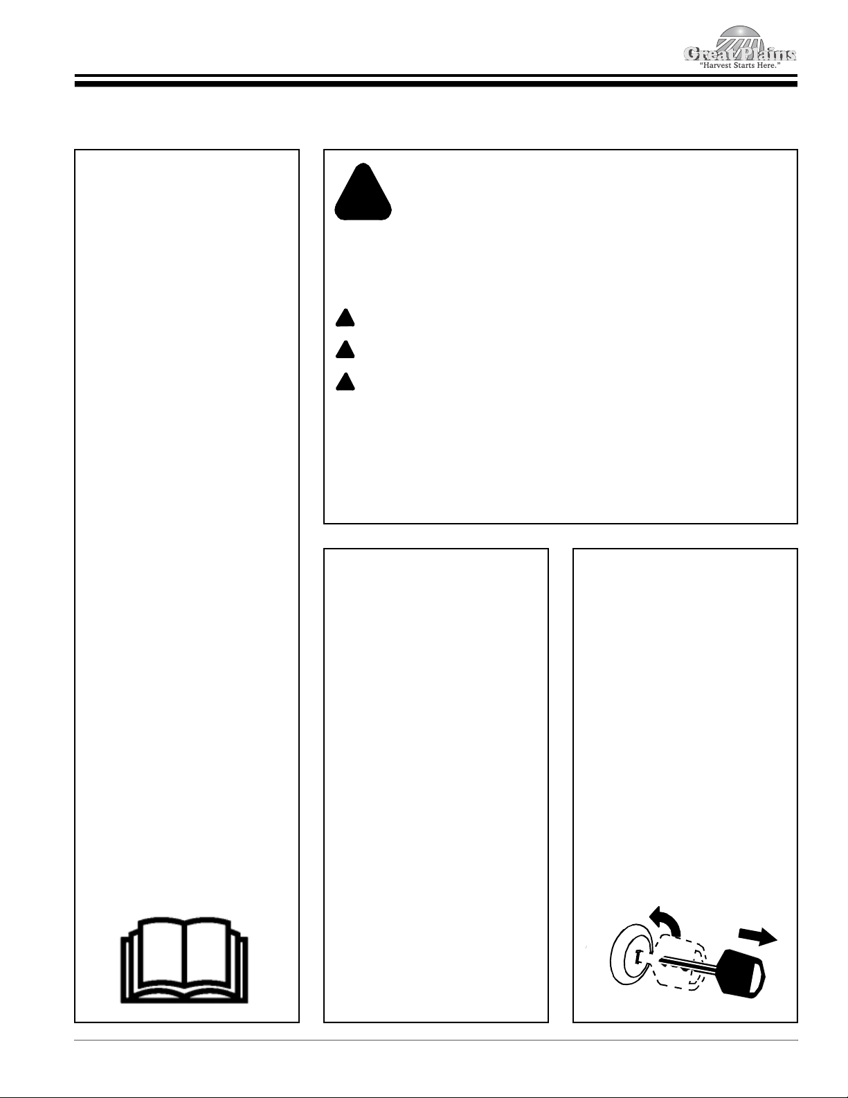
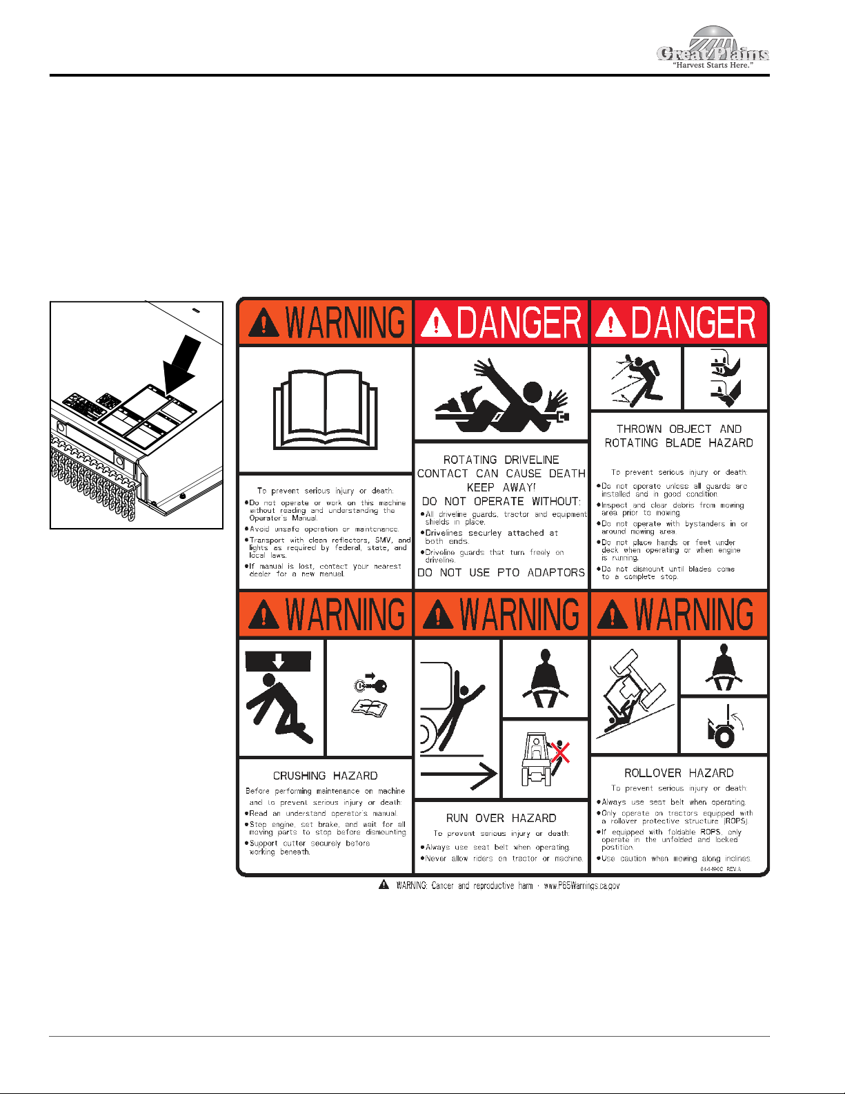
Look for the Safety Alert Symbol . . . . . . . . . . . . . . . 1
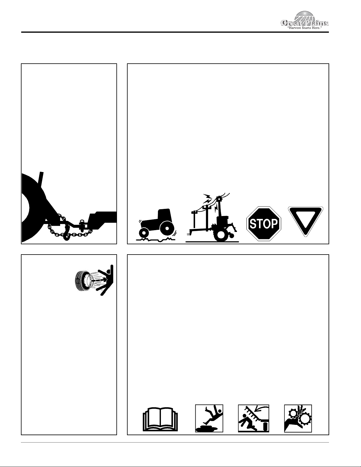
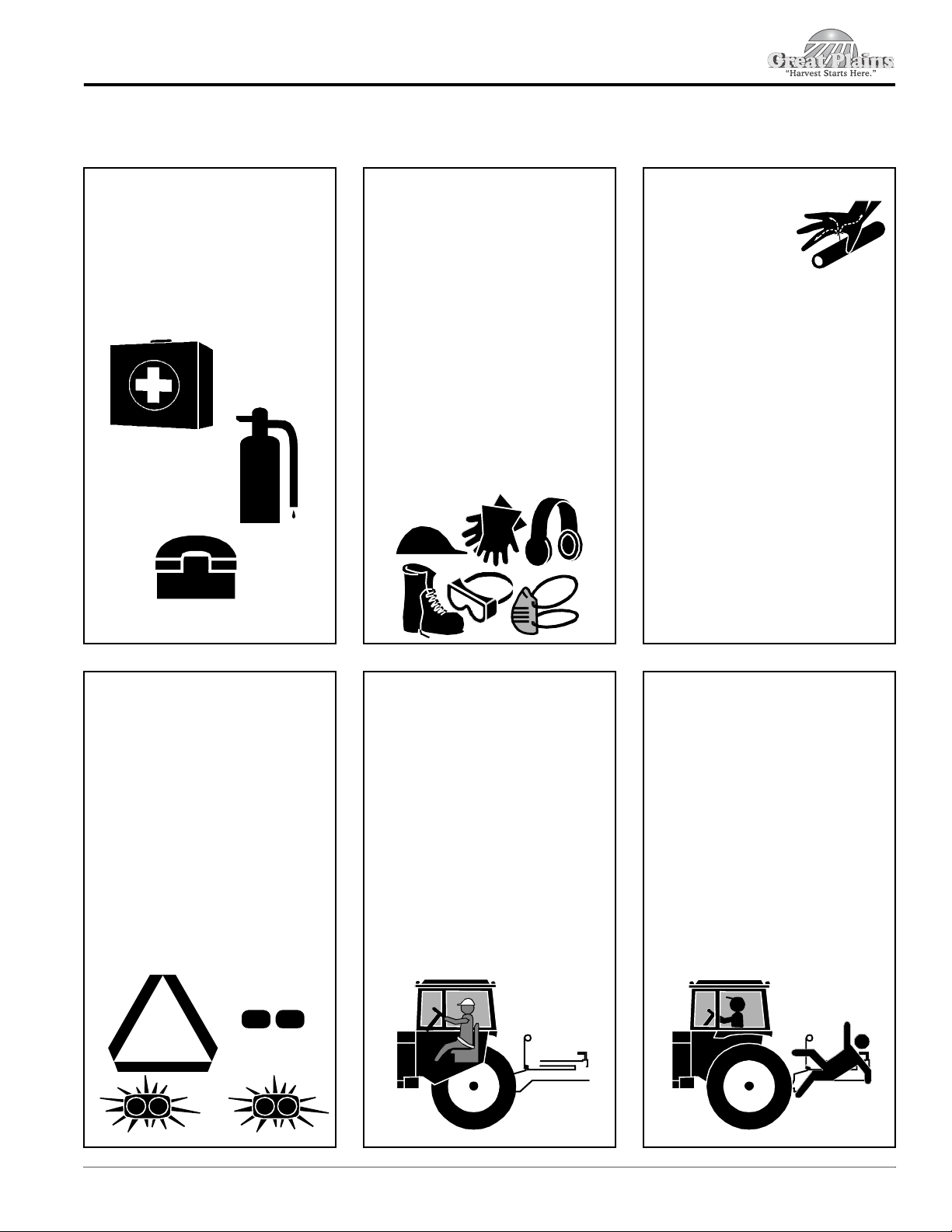
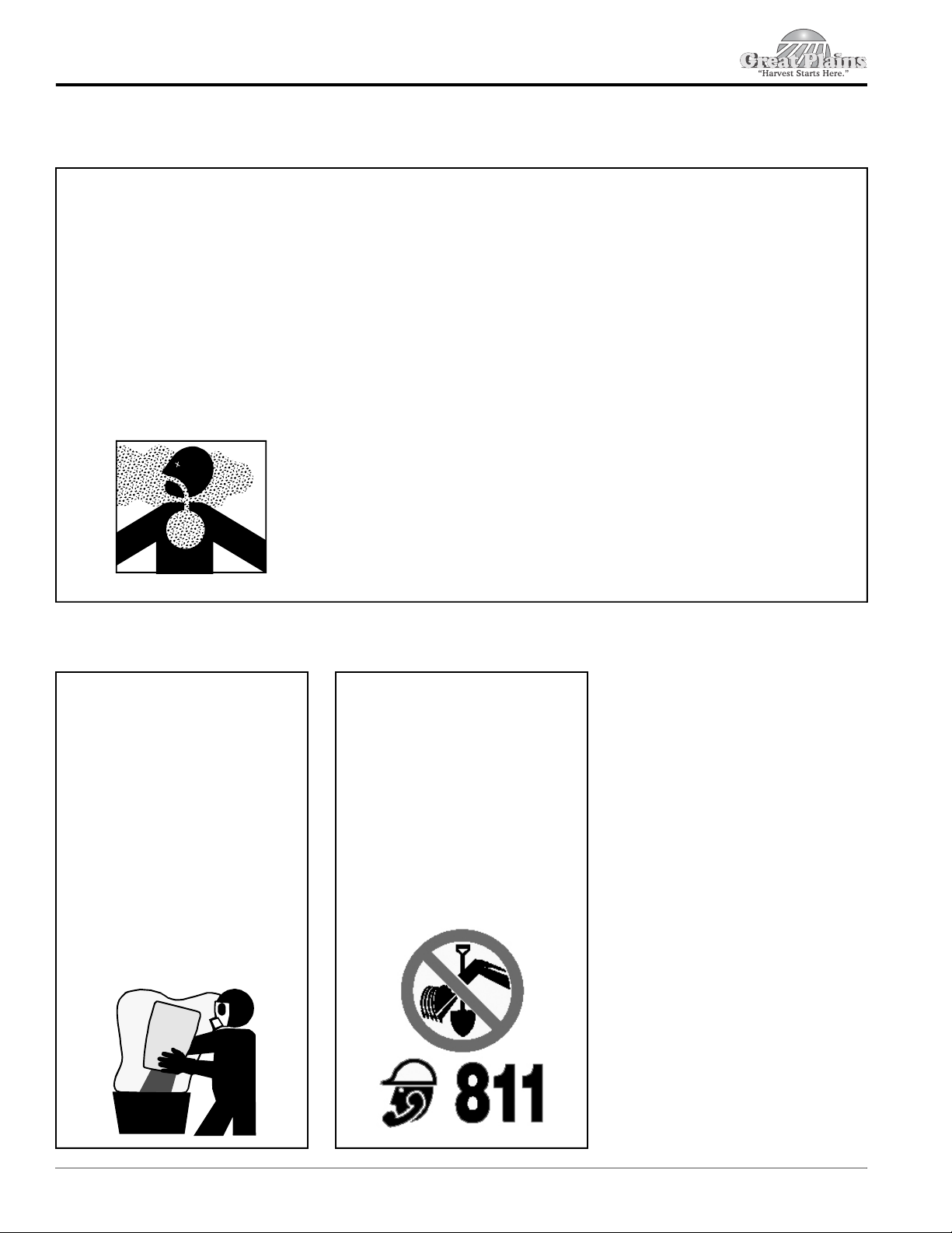
Safety Labels . . . . . . . . . . . . . . . . . . . . . . . . . . . . . 6
Introduction . . . . . . . . . . . . . . . . . . . . . . . . . . 11
Application . . . . . . . . . . . . . . . . . . . . . . . . . . . . . . 11
Using This Manual . . . . . . . . . . . . . . . . . . . . . . . . 11
Owner Assistance . . . . . . . . . . . . . . . . . . . . . . . . . 11
Serial Number . . . . . . . . . . . . . . . . . . . . . . . . . . 11
Section 1: Assembly & Set-Up . . . . . . . . . . . 12
Tractor Requirements . . . . . . . . . . . . . . . . . . . . . . 12
Dealer Preparations . . . . . . . . . . . . . . . . . . . . . . . 12
Gearbox Vent Plugs & Dipsticks . . . . . . . . . . . . . . 13
Vented Dipstick Installation . . . . . . . . . . . . . . . . 13
Torque Requirements . . . . . . . . . . . . . . . . . . . . . . 13
Tractor Shutdown Procedure . . . . . . . . . . . . . . . . 13
Getting Started . . . . . . . . . . . . . . . . . . . . . . . . . . . 13
3-Point Mounted Rotary Cutter . . . . . . . . . . . . . 13
Semi-Mount Rotary Cutter . . . . . . . . . . . . . . . . . 13
Pull-Type Rotary Cutter . . . . . . . . . . . . . . . . . . . 13
3-Point Assembly & Set-Up . . . . . . . . . . . . . . . . . . 14
Hitch Assembly (3-Point) . . . . . . . . . . . . . . . . . . 14
Spring Hose Loop Assembly (3-Point) . . . . . . . . 15
Driveline Installation (3-Point) . . . . . . . . . . . . . . 15
RCF(M)3696 Tailwheels (3-Point) . . . . . . . . . . . 16
RCF(M)3610 Tailwheels (3-Point) . . . . . . . . . . . 17
RCF(M)3696 Hitch Hook-Up (3-Point) . . . . . . . . 18
RCF(M)3610 Hitch Hook-Up (3-Point) . . . . . . . . 19
Driveline Hook-up (3-Point) . . . . . . . . . . . . . . . . 20
Hydraulic Hook-up Option (3-Point) . . . . . . . . . . 21
Hitch Pin Modification (3-Point & Semi) . . . . . . . 21
Semi-Mount Assembly & Set-Up . . . . . . . . . . . . . . 23
Spring Hose Loop Assembly (Semi-Mount) . . . . 23
Driveline Installation (Semi-Mount) . . . . . . . . . . 23
RCF(M)3696 Tailwheels (Semi-Mount) . . . . . . . 24
RCF(M)3610 Tailwheels (Semi-Mount) . . . . . . . 25
Hitch Hook-Up (Semi-Mount) . . . . . . . . . . . . . . . 26
Driveline Hook-up (Semi-Mount) . . . . . . . . . . . . 27
Hydraulic Hook-up (Semi-Mount) . . . . . . . . . . . . 27
Check Driveline Collapsible Length . . . . . . . . . . . . 28
Assemble Inner & Outer Driveline Halves . . . . . 28
Check Driveline Clearance . . . . . . . . . . . . . . . . . . 29
Pull-Type Assembly & Set-Up . . . . . . . . . . . . . . . . 30
Tailwheel Lift Options . . . . . . . . . . . . . . . . . . . . . 30
Axle Assembly (Pull-Type) . . . . . . . . . . . . . . . . . 30
Spring Hose Loop (Pull-Type) . . . . . . . . . . . . . . 31
Tongue Assembly (Pull-Type) . . . . . . . . . . . . . . 31
Park Jack Assembly (Pull-Type) . . . . . . . . . . . . . 31
Equal Angle Driveline (Pull-Type) . . . . . . . . . . . . 32
Constant Velocity Driveline (Pull-Type) . . . . . . . 33
Hitch Hook-Up (Pull-Type) . . . . . . . . . . . . . . . . . 34
Safety Chain Hook-Up For Pull-Type . . . . . . . . . 35
Hydraulic Hook-Up (Pull-Type) . . . . . . . . . . . . . . 35
Purge Hydraulic System (Pull-Type) . . . . . . . . . 35
Section 2: Assembly of Optional Equipment 36
Chain Safety Guards (Optional) . . . . . . . . . . . . . . 36
Front Chain Guards . . . . . . . . . . . . . . . . . . . . . . 36
Rear Chain Guard . . . . . . . . . . . . . . . . . . . . . . . 36
Rubber Safety Guards (Optional) . . . . . . . . . . . . . 37
Front Rubber Guards . . . . . . . . . . . . . . . . . . . . . 37
Rear Rubber Guard . . . . . . . . . . . . . . . . . . . . . . 37
Pull-Type Hitch Options . . . . . . . . . . . . . . . . . . . . . 38
Swivel Clevis Hitch . . . . . . . . . . . . . . . . . . . . . . . 38
Performance Hitch . . . . . . . . . . . . . . . . . . . . . . . 38
Change Out Hitches . . . . . . . . . . . . . . . . . . . . . . 38
Check Chains (Accessory) . . . . . . . . . . . . . . . . . . 39
Section 3: Adjustments . . . . . . . . . . . . . . . . . 41
Park Jack Angle Alignment . . . . . . . . . . . . . . . . . . 41
Deck Leveling & Height Adjustment . . . . . . . . . . . 42
3-Point With Beam Arms . . . . . . . . . . . . . . . . . . 42
3-Point or Semi-Mount With Rear Axle . . . . . . . . 44
Level Front To Back . . . . . . . . . . . . . . . . . . . . . . 45
Pull-Type With Rear Axle . . . . . . . . . . . . . . . . . . 46
Section 4: Operating Instructions . . . . . . . . . 48
Operating Checklist . . . . . . . . . . . . . . . . . . . . . . . . 48
Safety Information . . . . . . . . . . . . . . . . . . . . . . . . . 48
Inspect Tractor & Cutter . . . . . . . . . . . . . . . . . . . . 49
Transporting . . . . . . . . . . . . . . . . . . . . . . . . . . . . . 50
Blade Engagement & Disengagement . . . . . . . . . . 50
Field Operation . . . . . . . . . . . . . . . . . . . . . . . . . . . 50
Crossing Steep Ditches & Banks . . . . . . . . . . . . 51
Turning Angles for Pull-Type Cutters . . . . . . . . . 51
Unhook 3-Point or Semi-Mount . . . . . . . . . . . . . . . 52
Unhook Pull-Type . . . . . . . . . . . . . . . . . . . . . . . . . 53
General Operating Instructions . . . . . . . . . . . . . . . 54
Section 5: Maintenance & Lubrication . . . . . 55
Maintenance . . . . . . . . . . . . . . . . . . . . . . . . . . . . . 55
Hydraulic System . . . . . . . . . . . . . . . . . . . . . . . . . 55
Tire Maintenance . . . . . . . . . . . . . . . . . . . . . . . . . . 55
Cutter Blade Maintenance . . . . . . . . . . . . . . . . . . . 56
Driveline Slip-Clutch . . . . . . . . . . . . . . . . . . . . . . . 58
Flex Couplers . . . . . . . . . . . . . . . . . . . . . . . . . . . . 60
Continue Table of Contents on next page

Table of Contents Continued
8/20/21
Table of Contents
iv
Skid Shoe Maintenance . . . . . . . . . . . . . . . . . . . . 60
Long-Term Storage . . . . . . . . . . . . . . . . . . . . . . . . 61
Ordering Replacement Parts . . . . . . . . . . . . . . . . . 61
Lubrication Points . . . . . . . . . . . . . . . . . . . . . . . . . 62
Tailwheel Spindle Tubes . . . . . . . . . . . . . . . . . . 62
Tailwheel Hubs . . . . . . . . . . . . . . . . . . . . . . . . . . 62
Pillow Bearing (Pull-Type Cutter) . . . . . . . . . . . . 62
Ratchet Jack . . . . . . . . . . . . . . . . . . . . . . . . . . . 62
Gearbox . . . . . . . . . . . . . . . . . . . . . . . . . . . . . . . 63
T-Gearbox . . . . . . . . . . . . . . . . . . . . . . . . . . . . . 63
RCF(M)3610 Flex Coupler . . . . . . . . . . . . . . . . . 63
Driveline U-Joints & Profile Shields . . . . . . . . . . 64
CV Driveline U-Joints & Profile Shields . . . . . . . 64
Telescoping Driveline Profiles With Zerks . . . . . 64
Telescoping Driveline Profiles Without Zerks . . . 65
Section 6: Specifications & Capacities . . . . 66
Section 7: Features & Benefits . . . . . . . . . . . 68
Section 8: Troubleshooting . . . . . . . . . . . . . 69
Section 9: Torque & Tire Inflation Charts . . 70
Section 10: Warranty . . . . . . . . . . . . . . . . . . . 71

Important Safety Information
8/20/21 1
Important Safety Information
Listed below are common practices that may or may not be applicable to the products
described in this manual.
Tractor Shutdown & Storage
If engaged, disengage power
take-off.
Park on solid, level ground and
lower implement until it is flat on
the ground or on non-concrete
support blocks.
Put tractor in park or set park
brake.
Turn off engine and remove
ignition key to prevent
unauthorized starting.
Relieve all hydraulic pressure to
auxiliary hydraulic lines.
Wait for all components to stop
before leaving operator’s seat.
Use steps, grab-handles and
anti-slip surfaces when stepping
on and off the tractor.
OFF
REMOVE
Safety Precautions for
Children
Tragedy can occur if the operator
is not alert to the presence of
children, Children generally are
attracted to implements and their
work.
Never assume children will remain
where you last saw them.
Keep children out of the work area
and under the watchful eye of a
responsible adult.
Be alert and shut the implement
and tractor down if children enter
the work area.
Never carry children on the tractor
or implement. There is not a safe
place for them to ride. They may
fall off and be run over or interfere
with the control of the power
machine.
Never allow children to operate the
power machine, even under adult
supervision.
Never allow children to play on the
power machine or implement.
Use extra caution when backing
up. Before the tractor starts to
move, look down and behind to
make sure the area is clear.
Safety at All Times
Careful operation is your best
assurance against an accident.
All operators, no matter how much
experience they may have, should
carefully read this manual and
other related manuals, or have the
manuals read to them, before
operating the power machine and
this implement.
Thoroughly read and understand
the “Safety Label” section. Read
all instructions noted on them.
Do not operate the equipment
while under the influence of drugs
or alcohol as they impair the ability
to safely and properly operate the
equipment.
The operator should be familiar
with all functions of the tractor and
attached implement, and be able
to handle emergencies quickly.
Make sure all guards and shields
appropriate for the operation are in
place and secured before
operating the implement.
Keep all bystanders away from
equipment and work area.
Start tractor from the driver’s seat
with hydraulic controls in neutral.
Operate tractor and controls from
the driver’s seat only.
Never dismount from a moving
tractor or leave tractor unattended
with engine running.
Do not allow anyone to stand
between tractor and implement
while backing up to implement.
Keep hands, feet, and clothing
away from power-driven parts.
While transporting and operating
equipment, watch out for objects
overhead and along side such as
fences, trees, buildings, wires, etc.
Do not turn tractor so tight as to
cause hitched implement to ride
up on the tractor’s rear wheel.
Store implement in a safe and
secure area where children
normally do not play. When
needed, secure implement against
falling with support blocks.
Look for the Safety Alert Symbol
The SAFETY ALERT SYMBOL indicates there is a potential hazard
to personal safety and extra precaution must be taken. When you
see this symbol, be alert and carefully read the message that
follows it. Hazard control, and accident prevention are dependent
upon the awareness, concern, prudence, and proper training of
personnel involved in the operation, transport, maintenance, and
storage of equipment.
!
Be Aware of Signal Words
A signal word designates a degree or level of hazard seriousness. They are:
DANGER:
!
WARNING:
CAUTION:
!
!
Indicates a hazardous situation that, if not avoided, will result
in death or serious injury.
Indicates a hazardous situation that, if not avoided, could
result in death or serious injury.
Indicates a hazardous situation that, if not avoided, may result
in minor or moderate injury.
Be Aware of Special Notices
Special notices are intended to point out important and helpful information that
should be followed. They are usually placed inside a box. They are:
Indicates that equipment or property damage could result if
instructions are not followed.
Indicates supplementary explanations that will be helpful when
using the equipment.
IMPORTANT:
NOTE:

Important Safety Information
8/20/21
2
Listed below are common practices that may or may not be applicable to the products
described in this manual.
Practice Safe Maintenance
Understand procedure before doing
work. Refer to the Operator’s
Manual for additional information.
Work on a level surface in a clean
dry area that is well-lit.
Lower implement to the ground and
follow all shutdown procedures
before leaving the operator’s seat to
perform maintenance.
Do not work under any hydraulically
supported equipment. It can settle,
suddenly leak down, or be lowered
accidentally. If it is necessary to
work under the equipment,
securely support it with stands or
suitable blocking beforehand.
Use properly grounded electrical
outlets and tools.
Use correct tools and equipment for
the job that are in good condition.
Allow equipment to cool before
working on it.
Disconnect battery ground cable (-)
before servicing or adjusting
electrical systems or before welding
on implement.
Inspect all parts. Make certain
parts are in good condition &
installed properly.
Replace parts on this implement
with genuine Great Plains parts
only. Do not alter this implement in
a way which will adversely affect its
performance.
Do not grease or oil implement
while it is in operation.
Remove buildup of grease, oil, or
debris.
Always make sure any material and
waste products from the repair and
maintenance of the implement are
properly collected and disposed.
Remove all tools and unused parts
from equipment before operation.
Do not weld or torch on galvanized
metal as it will release toxic fumes.
Transport Safely
Comply with federal, state, and
local laws.
Use towing vehicle and trailer of
adequate size and capacity. Secure
equipment towed on a trailer with
tie downs and chains.
Sudden braking can cause a towed
trailer to swerve unexpectedly.
Reduce speed if towed trailer is not
equipped with brakes.
Avoid contact with any over head
utility lines or electrically charged
conductors.
Always drive with load on end of
loader arms low to the ground.
Always drive straight up and down
steep inclines with heavy end of a
tractor with loader attachment on
the “uphill” side.
Engage park brake when stopped
on an incline.
Maximum transport speed for an
attached equipment is 20 mph. DO
NOT EXCEED. Never travel at a
speed which does not allow
adequate control of steering and
stopping. Some rough terrains
require a slower speed.
As a guideline, use the following
maximum speed weight ratios for
attached equipment:
20 mph when weight of attached
equipment is less than or equal
to the weight of machine towing
the equipment.
10 mph when weight of attached
equipment exceeds weight of
machine towing equipment but
not more than double the weight.
IMPORTANT: Do not tow a load
that is more than double the weight
of the vehicle towing the load.
Use A Safety Chain
A safety chain will help control
drawn machinery should it
separate from the tractor drawbar.
Use a chain with the strength
rating equal to or greater than the
gross weight of the towed
implement.
Attach the chain to the tractor
drawbar support or other specified
anchor location. Allow only
enough slack in the chain to
permit turning.
Always hitch the implement to the
machine towing it. Do not use the
safety chain to tow the implement.
Tire Safety
Tire changing
can be
dangerous
and must be
performed by
trained personnel using the
correct tools and equipment.
Always properly match the wheel
size to the properly sized tire.
Always maintain correct tire
pressure. Do not inflate tires
above recommended pressures
shown in the Operator’s Manual.
When inflating tires, use a clip-on
chuck and extension hose long
enough to allow you to stand to
one side and NOT in front of or
over the tire assembly. Use a
safety cage if available.
Securely support the implement
when changing a wheel.
When removing and installing
wheels, use wheel handling
equipment adequate for the
weight involved.
Make sure wheel bolts have been
tightened to the specified torque.

Important Safety Information
8/20/21 3
Listed below are common practices that may or may not be applicable to the products
described in this manual.
Use Seat Belt and ROPS
Great Plains recommends the use
of a CAB or roll-over-protective-
structures (ROPS) and seat belt
in almost all power machines.
Combination of a CAB or ROPS
and seat belt will reduce the risk
of serious injury or death if the
power machine should be upset.
If ROPS is in the locked-up
position, fasten seat belt snugly
and securely to help protect
against serious injury or death
from falling and machine overturn.
Keep Riders Off
Machinery
Never carry riders on the tractor or
implement.
Riders obstruct operator’s view
and interfere with the control of
the power machine.
Riders can be struck by objects or
thrown from the equipment.
Never use the tractor or
implement to lift or transport
riders.
Prepare for Emergencies
Be prepared if a fire starts.
Keep a first aid kit and fire
extinguisher handy.
Keep emergency numbers for
doctor, ambulance, hospital, and
fire department near the phone.
911
Use Safety
Lights and Devices
A slow moving power machine
can create a hazard when driven
on public roads. They are difficult
to see, especially at night. Use the
Slow Moving Vehicle (SMV) sign
when on public roads.
Flashing warning lights and turn
signals are recommended
whenever driving on public roads.
Avoid High Pressure
Fluids
Escaping fluid
under pressure will
penetrate the skin or
eyes causing serious injury.
Relieve all residual pressure
before disconnecting hydraulic
lines or performing work on the
hydraulic system.
Make sure all hydraulic fluid
connections are properly
tightened/torqued and all
hydraulic hoses and lines are in
good condition before applying
pressure to the system.
Use a piece of paper or
cardboard, NOT BODY PARTS,
to check for suspected leaks.
Wear protective gloves and
safety glasses or goggles when
working with hydraulic systems.
DO NOT DELAY. If an accident
occurs, seek immediate
emergency medical care or
gangrene may result.
Wear Personal Protective
Equipment (PPE)
Wear protective clothing and
equipment appropriate for the job
such as safety shoes, safety,
glasses, hard hat, dust mask,
and ear plugs.
Clothing should fit snug without
fringes and pull strings to avoid
entanglement with moving parts.
Prolonged exposure to loud noise
can cause hearing impairment or
hearing loss. Wear suitable
hearing protection such as
earmuffs or earplugs.
Operating a machine safely
requires the operator’s full
attention. Avoid wearing
headphones while operating
equipment.

Important Safety Information
8/20/21
4
Dig Safe - Avoid
Underground Utilities
USA: Call 811
CAN: digsafecanada.ca
Always contact your local utility
companies (electrical, telephone,
gas, water, sewer, and others)
before digging so that they may
mark the location of any
underground services in the area.
Be sure to ask how close you can
work to the marks they positioned.
Listed below are common practices that may or may not be applicable to the products
described in this manual.
Avoid crystalline Silica
(quartz) Dust
Because crystalline silica is a basic
component of sand and granite,
many activities at construction sites
produce dust containing crystalline
silica. Trenching, sawing, and boring
of material containing crystalline
silica can produce dust containing
crystalline silica particles. This dust
can cause serious injury to the
lungs (silicosis).
There are guidelines which should
be followed if crystalline silica
(quartz) is present in the dust.
Be aware of and follow OSHA
(or other local, State, or Federal)
guidelines for exposure to airborne
crystalline silica.
Know the work operations where
exposure to crystalline silica may
occur.
Participate in air monitoring or
training programs offered by the
employer.
Be aware of and use optional
equipment controls such as water
sprays, local exhaust ventilation,
and enclosed cabs with positive
pressure air conditioning if the
machine has such equipment.
Otherwise respirators shall be worn.
Where respirators are required, wear
a respirator approved for protection
against crystalline silica containing
dust. Do not alter respirator in any
way. Workers who use tight-fitting
respirators can not have beards/
mustaches which interfere with the
respirator seal to the face.
If possible, change into disposable
or washable work clothes at the
work site; shower and change into
clean clothing before leaving the
work site.
Do not eat, drink, use tobacco
products, or apply cosmetics in
areas where there is dust containing
crystalline silica.
Store food, drink, and personal
belongings away from the work
area.
Wash hands and face before eating,
drinking, smoking, or applying
cosmetics after leaving the exposure
area.
Handle
Chemicals Properly
Protective clothing should be
worn.
Handle all chemicals with care.
Follow instructions on container
label.
Agricultural chemicals can be
dangerous. Improper use can
seriously injure persons, animals,
plants, soil, and property.
Inhaling smoke from any type of
chemical fire can be a serious
health hazard.
Store or dispose of unused
chemicals as specified by the
chemical manufacturer.

Important Safety Information
8/20/21 5
This page left blank intentionally.

6
Important Safety Information
RCF3696, RCFM3696, RCF3610, & RCFM3610 Rotary Cutters 327-154M
Table of Contents
8/20/21
Safety Labels
Your Rotary Cutter comes equipped with all safety labels in
place. They were designed to help you safely operate your
implement. Read and follow their directions.
1. Keep all safety labels clean and legible.
2. Refer to this section for proper label placement. Replace
all damaged or missing labels. Order new labels from your
nearest Great Plains dealer. To find your nearest dealer,
visit our dealer locator at www.greatplainsag.com.
3. Some new equipment installed during repair requires
safety labels to be affixed to the replaced component as
specified by Great Plains. When ordering new components
make sure the correct safety labels are included in the
request.
4. Refer to this section for proper label placement.
To install new labels:
a. Clean surface area where label is to be placed.
b. Spray soapy water onto the cleaned area.
c. Peel backing from label and press label firmly onto the
surface.
d. Squeeze out air bubbles with edge of a credit card or
with a similar type of straight edge.
844-190C
Safety Combo:
Important Safety Information

7
Important Safety Information
RCF3696, RCFM3696, RCF3610, & RCFM3610 Rotary Cutters 327-154M
Table of Contents
8/20/21
818-552C
Danger: Rotating driveline
2 - Places
Rear Gauge Wheels Not Shown for Clarity
33937
33937
33939
33937
838-615C
2" x 9" Amber Reflector (Left side only)
838-062C
3/4" x 4 5/16" Amber Reflector
2 - Places (Left & right side)
838-614C
2" x 9" Red Reflector
2 - Places (Left & right side)

8
Important Safety Information
RCF3696, RCFM3696, RCF3610, & RCFM3610 Rotary Cutters 327-154M
Table of Contents
8/20/21
Rear Gauge Wheels Not Shown for Clarity
33937
33938
33939
33939
818-555C
Danger: Rotating Blades
2- Places (Right front corner of deck
and right back side of deck)
818-556C
Danger:
Thrown Object
818-543C
Danger: Guard Missing
3 - Places (Beneath gearbox input shaft shields

9
Important Safety Information
RCF3696, RCFM3696, RCF3610, & RCFM3610 Rotary Cutters 327-154M
Table of Contents
8/20/21
Semi-Mount Rotary Cutter Only
Pull-Type Rotary Cutter Only
33937
35042
35042
33016
838-094C
Warning: High Pressure
818-142C
Danger: Rotating Driveline
818-681C
Notice: 20 MPH Max Travel Speed
Located on pull-type hitch and all gauge wheels

10
Important Safety Information
RCF3696, RCFM3696, RCF3610, & RCFM3610 Rotary Cutters 327-154M
Table of Contents
8/20/21
33937
22296
22296
35042
818-540C
Danger: Guard Missing Do Not Operate
818-130C (Shown)
Warning: 540 rpm
818-240C
Warning: 1000 rpm
818-552C
Danger: Rotating Driveline
Hazard Keep Away
858-558C
Caution: Driveline Damage

11
Introduction
RCF3696, RCFM3696, RCF3610, & RCFM3610 Rotary Cutters 327-154M
Table of Contents
8/20/21
Introduction
Owner Assistance
The dealer should complete the Online Warranty
Registration at the time of purchase. This information is
necessary to provide you with quality customer service.
The parts on your Rotary Cutter have been specially
designed by Great Plains and should only be replaced
with genuine Great Plains parts. Contact a Great Plains
dealer if customer service or repair parts are required.
Your Great Plains dealer has trained personnel, repair
parts, and equipment needed to service the implement.
Serial Number
For quick reference and prompt service, record model
and serial number on the inside cover page and again on
the warranty page. Always provide model number and
serial number when ordering parts and in all
correspondences with your Great Plains dealer. For
location of your serial number plate, see Figure 1.
Serial Number Plate Location
Figure 1
Further Assistance
Your dealer wants you to be satisfied with your new
Rotary Cutter. If for any reason you do not understand
any part of this manual or are not satisfied with the
service received, the following actions are suggested:
1. Discuss any problems you have with your implement
with your dealership service personnel so they can
address the problem.
2. If you are still not satisfied, seek out the owner or
general manager of the dealership, explain the
question/problem, and request assistance.
3. For further assistance write to:
Great Plains Service Department
1525 East North Street
P.O. Box 5060
Salina, KS. 67402-5060
Or go to www.greatplainsag.com and follow the contact
information at the bottom of your screen for our service
department.
33938
Great Plains welcomes you to the growing family of new
product owners. This Rotary Cutter has been designed
with care and built by skilled workers using quality
materials. Proper assembly, maintenance, and safe
operating practices will help you get years of satisfactory
use from this product.
Application
The heavy duty RCF(M)3696 and RCF(M)3610 Series
Rotary Cutters are designed and built by Land Pride to
provide excellent cutting performance on gently sloping
or slightly contoured right-of-ways, pastures, set-aside-
acres, or row crop fields. Their 8' (2.44 m) or 10' (3.05 m)
cutting width, 2" (5 cm) to 12" (30 cm) cutting height, and
ability to cut weeds and brush up to 3" (7.6 cm) in
diameter make them well suited for these applications.
They offer Quick Hitch adaptability with 540 or 1000 rpm
power take-off.
The RCF(M)3696 cutters are designed for Category
l or ll 3-point, semi-mount, or pull-type hitch. Tractor
horsepower requirement varies based on hitch type:
•3-point requires a 50-130 hp (37-97 kW) tractor
•Semi-mount requires a 40-130 hp (30-97 kW) tractor
•Pull-type requires a 35-130 hp (26-97 kW) tractor.
The RCF(M)3610 cutters are designed for Category
ll or lll 3-point, semi-mount, or pull-type hitch. Tractor
horsepower requirement varies based on hitch type:
•3-point requires a 60-130 hp (45-97 kW) tractor
•Semi-mount and pull-type require a 50-130 hp
(37-97 kW) tractor.
Heavy-duty stump jumpers, main driveline clutches, and
outboard flex couplers are offered for driveline and
gearbox protection. Safety guards around the cutter are
offered in either single chain, double chain, or rubber.
See “Specifications & Capacities” on page 66 and
“Features & Benefits” on page 68 for additional
information and performance enhancing options.
Using This Manual
•This Operator’s Manual is designed to help familiarize
the operator with safety, assembly, operation,
adjustments, troubleshooting, and maintenance. Read
this manual and follow the recommendations to help
ensure safe and efficient operation.
•The information contained within this manual was
current at the time of printing. Some parts may change
slightly to assure you of the best performance.
•To order a new Operator’s or Parts Manual, contact
your authorized dealer. Manuals can also be
downloaded, free-of-charge, from our website at
www.greatplainsag.com
Terminology
“Right” or “Left” as used in this manual is determined by
the direction the operator faces while sitting in the
operator’s seat looking forward unless otherwise stated.

12
Section 1: Assembly & Set-Up
RCF3696, RCFM3696, RCF3610, & RCFM3610 Rotary Cutters 327-154M
Table of Contents
8/20/21
Section 1: Assembly & Set-Up
Tractor Requirements
WARNING
!
To avoid serious injury or death:
•Do not use a tractor that is too small or too large. Small
tractors can be pushed around and flipped over. Large
tractors can damage the attached implement.
•Lightweight tractors with rear attached implements may
need weights added to the front to maintain steering control.
Consult your tractor Operator’s Manual to determine
proper weight requirements and maximum weight
limitations.
Tractor horsepower and weight must be capable of
controlling the cutter under all operating conditions.
Tractors outside the horsepower range must not be used.
Horsepower rating (RCF3696 & RCFM3696)
Three-Point Cat. I or II . . . . . . 50-130 hp (37-97 kW)
Semi-Mount. . . . . . . . . . . . . . 40-130 hp (30-97 kW)
Pull-Type . . . . . . . . . . . . . . . . 35-130 hp (26-97 kW)
Horsepower rating (RCF3610 & RCFM3610)
Three-Point . . . . . . . . . . . . . . 60-130 hp (45-97 kW)
Semi-Mount & Pull-Type . . . . 50-130 hp (37-97 kW)
3-Point hitch category
RCF3696 & RCFM3696 . . . . . . . . . . . . . .Cat. l or ll
RCF3610 & RCFM3610. . . . . . . . . . . . . . Cat. ll or lll
Power take-off Speed
RCF3696 and RCF3610 . . . . . . . . . . . . . . 540 rpm
RCFM3696 and RCFM3610 . . . . . . . . . . .1000 rpm
Power take-off shaft type:
RCF3696 and RCF3610 . . . . . . . . . 1 3/8"-6 Spline
RCFM3696 and RCFM3610 . . . . . 1 3/8"-21 Spline
Pull-Type Hitch
Refer to Figure 1-1:
Distances between center of drawbar hitch pin hole to
end of tractor power take-off shaft (“A” dimension) and
from top of drawbar hitch to center of power take-off shaft
(“B” dimension) must be maintained for Pull-type hitches.
“A” = 14" (36 cm) at 540 rpm
“A” = 16" (41 cm) at 1000 rpm
“B” = 8" (20 cm) at 540 and 1000 rpm
Power Take-Off to Drawbar Distance
Figure 1-1
IMPORTANT: Power take-off damage may occur if
distances “A” and “B” are not maintained.
22273
Power Take-Off Shaft
Drawbar
Ground Level
A
B
C
3-Point Hitch
The lower 3-point arms must be stabilized to prevent
side-to-side movement. Most tractors have sway blocks
or adjustable chains for this purpose.
Dealer Preparations
WARNING
!
To avoid serious injury or death:
Always secure cutter with an overhead crane, fork lift, or
other suitable lifting device before removing hardware bags,
shipping components, bands, lag screws, or hitch pins. The
cutter can suddenly fall.
Read and understand the operator’s manual for your
cutter. An understanding of how it works will aid in the
assembly and setup of your cutter.
It is best to go through the “Assembly Checklist” on this
page before assembling the cutter. Speed up your
assembly task and make the job safer by having all the
needed parts and equipment readily at hand.
Assembly Checklist
Check Refer to
Location of fasteners and pins.
NOTE: All hardware from the factory has
been installed in the location where it will be
used. If a part is temporarily removed for
assembly reasons, remember where it
goes. Keep parts separated.
Operator’s
& Parts
Manual
Be sure parts get used in the correct
location. By double checking while you
assemble, you will lessen the chance of
using a bolt that may be needed later.
Operator’s
Manual
Grease fittings are in place and lubricated. Page 62
Safety labels are correctly located and
legible. Replace if damaged. Page 6
Inflate tires to specified PSI air pressure.
Tighten wheel bolts to specified torque. Page 70
Red and amber reflectors are correctly
located and visible when the cutter is in the
transport position.
Page 6
Have a minimum of 2 people at hand while
assembling the cutter.
Operator’s
Manual
Have a fork lift or loader along with chains
and safety stands that are sized for the job
ready for the assembly task.
Operator’s
Manual
IMPORTANT: Leveling rods on pull-type cutters are
long and will make contact with the floor first when
lowering cutter to the floor. It is best to remove them
before lifting the cutter off the shipping crate.

13
Section 1: Assembly & Set-Up
RCF3696, RCFM3696, RCF3610, & RCFM3610 Rotary Cutters 327-154M
Table of Contents
8/20/21
Gearbox Vent Plugs & Dipsticks
Vent Plug Installation
Refer to Figure 1-2:
A vent plug is shipped loose and packaged with the
Operator’s Manual. Remove temporary solid plug on top
of T-box and replace with included 3/8" vent plug. See
your nearest Great Plains dealer if vent plug is missing.
Vented Dipstick Installation
Refer to Figure 1-3:
Vented dipsticks are shipped loose and packaged with
the Operator’s Manual. See your nearest Great Plains
dealer if dipstick is missing. Remove temporary pipe plug
from top of each gearbox and replace with supplied
dipsticks.
Torque Requirements
Refer to “Torque Values Chart” on page 70 to
determine correct torque values for common bolts. See
“Additional Torque Values” at bottom of chart for
exceptions to standard torque values.
Tractor Shutdown Procedure
The following are basic tractor shutdown procedures.
Follow these procedures and any additional shutdown
procedures provided in your tractor Operator’s Manual
before leaving the operator’s seat.
1. Reduce engine speed and disengage power take-off
if engaged.
2. Park tractor and implement on level, solid ground.
3. Lower implement to ground or onto non-concrete
support blocks.
4. Put tractor in park or set park brake, turn off engine,
and remove switch key to prevent unauthorized
starting.
5. Relieve all hydraulic pressure to auxiliary hydraulic
lines.
6. Wait for all components to come to a complete stop
before leaving the operator’s seat.
7. Use steps, grab-handles and anti-slip surfaces when
stepping on and off the tractor.
IMPORTANT: Gearboxes are shipped with solid
plugs in them to prevent oil loss during shipping and
handling. The solid plug on top of the gearbox must
be replaced with a vented dipstick before operating
the implement.
Figure 1-2
Figure 1-3
Getting Started
The RCF36 Series cutters can be purchased with either
3-point hitch, Semi-Mount hitch, or Pull-Type hitch.
3-Point Mounted Rotary Cutter
Refer to illustrations on cover of manual:
The 3-point Rotary Cutter is attached to the tractor’s
lower 3-point arms and upper center link. The lower
3-point arms are hydraulically adjusted to the cutting
height. The height of the rear tailwheels are manually or
hydraulically adjusted depending upon which option the
cutter is set-up with. The tailwheels should be adjusted to
hold the cutting blades slightly higher at the back than at
the front. The “3-Point Assembly & Set-Up” instructions
begin on page 14.
Semi-Mount Rotary Cutter
Refer to illustrations on Cover
The Semi-Mount cutter is attached to the tractor’s lower
3-point arms and have more freedom to float over uneven
terrain than does the 3-point mounted cutter. The lower 3-
point arms are hydraulically adjusted to the cutting
height. The rear tailwheels are manually adjusted with a
ratchet jack or hydraulically adjusted to hold the cutting
blades slightly higher at the back than at the front. The
“Semi-Mount Assembly & Set-Up” instructions begin
on page 23.
Pull-Type Rotary Cutter
Refer to illustrations on Cover
The Pull-Type cutter is attached to the tractor drawbar.
Cutting height is controlled with a hydraulic cylinder or
ratchet jack. Leveling rods keep the rear of the cutter
slightly higher than the front. The “Pull-Type Assembly
& Set-Up” instructions begin on page 30.
22320 Remove 3/8" T-Box Solid
Plug & Install Vent Plug
DO NOT
OVERFILL!
30216
Oil Level Plug
Remove Pipe
Plug Install
Vented Dip-
DO NOT
OVERFILL!

14
Section 1: Assembly & Set-Up
RCF3696, RCFM3696, RCF3610, & RCFM3610 Rotary Cutters 327-154M
Table of Contents
8/20/21
3-Point Hitch Assembly (RCF(M)3696 Shown)
Figure 1-4
33942a
3-Point Assembly & Set-Up
The following pages are Assembly & Set-Up Instructions
for 3-point cutters. Not all instructions will apply to your
cutter. See “Semi-Mount Assembly & Set-Up” on page
23 and “Pull-Type Assembly & Set-Up” on page 30.
Hitch Assembly (3-Point)
Refer to Figure 1-4:
1. Attach Right-hand A-Frame (#3) to hitch plate as
shown with 7/8"-9 x 2 1/2" GR5 cap screw (#7), flat
washer (#10), bushing (#4), and nylock nut (#8).
2. Repeat step 1 for the left-hand A-Frame (#2).
3. Attach short braces (#5) to A-Frames (#2 & #3) with
1" x 3 3/16" clevis pin (#14), three flat washers (#11),
and cotter pin (#12) at the back as shown. Bend one
or more legs of the cotter pin to retain the clevis pin.
4. Secure 1 1/4" OD. bushing (#1) between the two
A-Frame hitch plates (#2 & #3) with 1"-8 x 4 1/2" cap
screw (#6) and nylon locknut (#9).
5. Install remaining clevis pin (#14), flat washer (#11)
and hairpin cotter (#13) to the A-Frame hitch
assembly (#2 & #3) as shown.
NOTE: Do not tighten hardware until assembly is
complete. See “Torque Values Chart” on page 70.
6. Attach driveline hook (#17) to A-frame (#2) using
5/16"-18 x 1 1/4" bolt (#18) and locknut (#19).
7. Tighten all hardware to the correct torque.
8. Insert hitch pins (#15) in clevis as shown and secure
as follows:
•RCF(M)3696: With hairpin cotters (#16) as shown.
•RCF(M)3610, Refer to Figure 1-10 on page 19:
With linchpins (#5) in hitch pins (#1).

15
Section 1: Assembly & Set-Up
RCF3696, RCFM3696, RCF3610, & RCFM3610 Rotary Cutters 327-154M
Table of Contents
8/20/21
3-Point Spring Hose Loop Mount
Figure 1-5
Spring Hose Loop Assembly (3-Point)
Refer to Figure 1-5:
3-Point mounted cutters with hydraulic cylinder option are
shipped with a spring hose loop. Skip to “Driveline
Installation (Semi-Mount)” on this page if hydraulics are
not included.
1. Attach mounting bracket (#1) with 3/4"-10 x 1 1/2"
GR5 cap screw (#3) and locknut (#5) to the outside of
the right-hand clevis as shown. Tighten locknut to the
correct torque.
2. Attach spring hose loop (#7) to mounting bracket (#1)
with 3/8"-16 x 1" GR5 cap screw (#2), flat washer
(#6), and locknut (#4). Tighten locknut to the correct
torque.
35005
Driveline Installation (Hitch Removed For Clarity)
Figure 1-6
Driveline Installation (3-Point)
Refer to Figure 1-6:
DANGER
!
To avoid serious injury or death:
Make certain driveline yokes are securely fastened at each
end. A loose yoke can work free allowing the driveline to
rotate uncontrollably.
1. Remove rubber protective sleeve (#4) from gearbox
input shaft and discard.
2. Pry open access doors (#5) in the gearbox shield by
placing a tool in the notch at the back of both doors.
3. Remove existing conical dog pin or bolts (#1), flat
washer(s) (#3), and nut(s) (#2) from slip-clutch end
of driveline (#6).
4. Slide slip-clutch end of driveline (#6) onto gearbox
input shaft. Make certain that the slip-clutch is fully
onto the shaft splines.
5. Attach slip-clutch end of driveline to gearbox input
shaft with removed conical dog pin or bolts (#1), flat
washer(s) (#3), and nut(s) (#2). Tighten conical dog
pin or bolts (#1) to 45-50 ft-lb torque.
6. Push/pull on driveline yoke to ensure it is securely
fastened to the gearbox shaft.
7. Rotate access doors (#5) closed and snap in place.
8. Rotate driveline storage hook down and place
driveline (#6) in storage hook.
33944
IMPORTANT: The driveline must be lubricated
before putting it into service. Refer to “Lubrication
Points” on page 62.
NOTE: If preferred, the front guards may be
assembled first. See “Assembly of Optional
Equipment” on page 36 for front guard instructions.

16
Section 1: Assembly & Set-Up
RCF3696, RCFM3696, RCF3610, & RCFM3610 Rotary Cutters 327-154M
Table of Contents
8/20/21
35203
RCF(M)3696 Model With 15" Tailwheel Assembly
35204
RCF(M)3696 Model With 21" Tailwheel Assembly
RCF(M)3696 3-Point Tailwheel Assembles
Figure 1-7
3. Insert tailwheel spindle (#6) into pivot tube on end of
tailwheel arm (#2).
4. Install 2 1/4" O.D. machine washers (#4) over each
tailwheel spindle (#6) and secure with 3/8" x 2 1/2"
roll pins (#7).
5. Tail wheel arms (#2) should be adjusted to customer
preference. When completed, they should be equal
distance from center line of hydraulic lift cylinder.
a. Loosen hex flange locknuts (#8) and adjust
tailwheel arms (#2) in or out to desired locations.
b. Tighten locknuts (#8) to the correct torque.
6. Continue with “RCF(M)3696 Hitch Hook-Up (3-
Point)” on page 18.
RCF(M)3696 Tailwheels (3-Point)
These instructions apply only to 96" models with the
optional rear axle hydraulic lift. If hydraulics are not
included with your cutter, skip to “RCF(M)3696 Hitch
Hook-Up (3-Point)” on page 15.
Refer to Figure 1-7:
1. There are several cylinder mounting lugs (#5) that
can be installed on axle (#1). Refer to NOTES IN
BOLD in Figure 1-7 to make sure your cutter is
equipped with the correct mounting lug and that the
notch in the lug is located on the axle properly. See
your nearest Great Plains dealer if it is not correct.
2. Install washers (#3) as follows:
RCF(M)3696 With 15" Tailwheels
Install two 2 1/4" O.D. machine washers (#3) onto
each tailwheel spindle (#6).
RCF(M)3696 With 21" Tailwheels
Install one special 4" O.D. harden washer (#3) onto
each tailwheel spindle (#6).
NOTE: If preferred, rear guards may be assembled
before the tailwheels. See “Assembly of Optional
Equipment” on page 36 for rear guard instructions.
This manual suits for next models
3
Table of contents
Other GREAT PLAINS Cutter manuals