SilverLeaf Electronics VMS PC User manual

SilverLeaf Electronics, Inc.
2472 SW Ferry St. • Albany, OR 97322 • (888) 741-0259
www.silverleafelectronics.com
Version 2.5
Owner’s Manual
23
Quick Start Guide
Step One: Install the Software
Insert the Installation Disk into your CDROM drive. From the Windows Start Menu,
select “My Computer . .”, Then right click the CDROM drive and click on explore. Double click
on “VMSpc25_Install.exe” The installation program will load the software on your hard drive
and create menu items and icons for your convenience. In Windows Vista when the install
utility prompts for an installation location, install to C:. You can also download the software
from our web site - after downloading the VMSpc Distribution Disk file, unzip it, then open the
distribution disk folder, and double click VMSpc25_Install.exe and the installation will start.
Step Two: Install the Hardware
Your package includes a small black box labeled “VMSpc J1708/J1939 Interface”.
(We’ll call this the “JIB” throughout the manual.) An ordinary USB cable connects the JIB to
the PC. Aspecial cable connects the JIB to the diagnostic plug located under the dash in the
vehicle. Plug them all in - there is only one way they can fit.
Step Three: Configure the Program
Turn the vehicle key to “Run”, or start the engine. Start VMSpc. If data does not im-
mediately appear on the screen, select “Advanced” and “Communications”. Change the Port
setting to the proper setting for your COM port - when it’s right, the Status will change to “Ok”.
If your computer screen is smaller than the default configuration, the gauges will not fit
properly and some will hang off the edge of the screen. Select “File” and “Open” and load the
“Default - 640.scr”.
You may now rearrange the gauges on the screen, create new gauges and other items,
and customize the arrangement as you see fit. When you are finished, save your settings by
selecting “File” and “Save”.
One of the first gauges you should create is an Odometer. See the Odometer section
for details.
Contents
Quick Start Guide..............................................................................................2
How VMSpc Works............................................................................................4
The Basics.........................................................................................................5
Simple and Scan Gauges..................................................................................8
Odometers.......................................................................................................10
Tank Minder.....................................................................................................12
Transmission Indicators...................................................................................13
MultiBars..........................................................................................................14
Histograms......................................................................................................15
Clocks..............................................................................................................16
Pictures............................................................................................................16
Text..................................................................................................................16
Diagnostics......................................................................................................17
Maintenance Tracking.....................................................................................18
Message Boxes...............................................................................................20
PressurePro Tire Monitoring............................................................................22
Advanced Features.........................................................................................24
Communications..............................................................................................28
Parameter Editing............................................................................................29
AFew Tips and Ideas......................................................................................30
Warranty..........................................................................................................32
45
The Basics
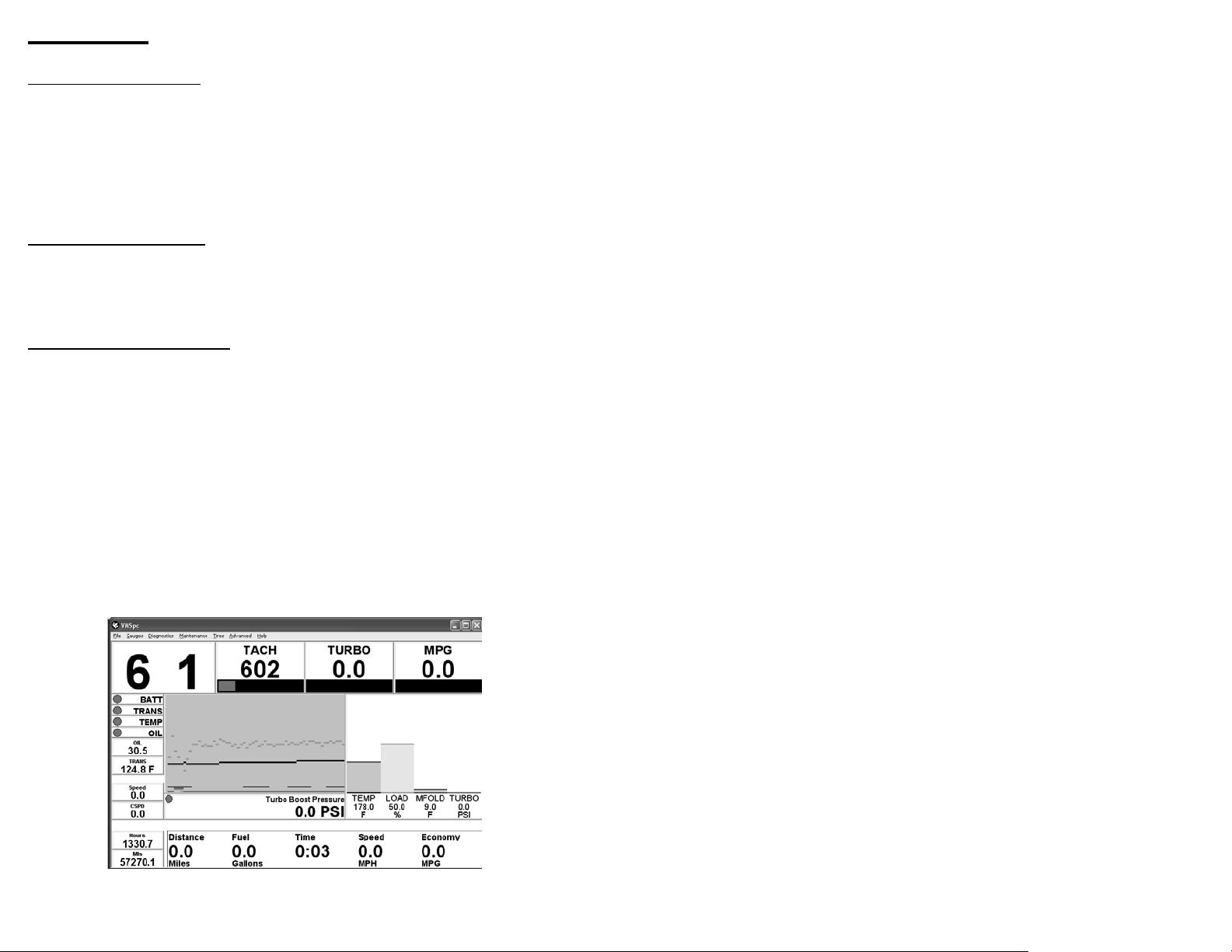
VMSpc’s main program window consists of just a frame, a menu bar, and a large open
area where the gauges dwell. The main window can be sized and moved like any other pro-
gram - VMSpc does not have to use the full screen. Consult the Windows manuals for help in
arranging multiple programs on the screen.
The “gauges” are a motley collection of various small panels, and they take many
forms. They can be as simple as a bit of text or a picture, or as complex as a moving bar
graph (“histogram”). The gauges can be moved anywhere on the screen, made any size
desired, and customized in a variety of ways.
Moving and Sizing Gauges
To manipulate a gauge, first click on the gauge with the mouse. The border of the
gauge will thicken to indicate which gauge you selected. To move the gauge, click on it again
and hold the mouse button down, then move the mouse to “drag” the gauge where you want
it. To change the size of the gauge, click on the border of the gauge and “drag” it where you
want. The text and graphics in each gauge will automatically adjust their size to fit in the avail-
able space.
Gauges can overlap, or even cover each other, but this isn’t generally very useful. The
program also deliberately reduces the precision with which you can adjust the size. This is
intended to make it easier to keep the gauges lined up straight and looking sharp.
Customizing Gauges
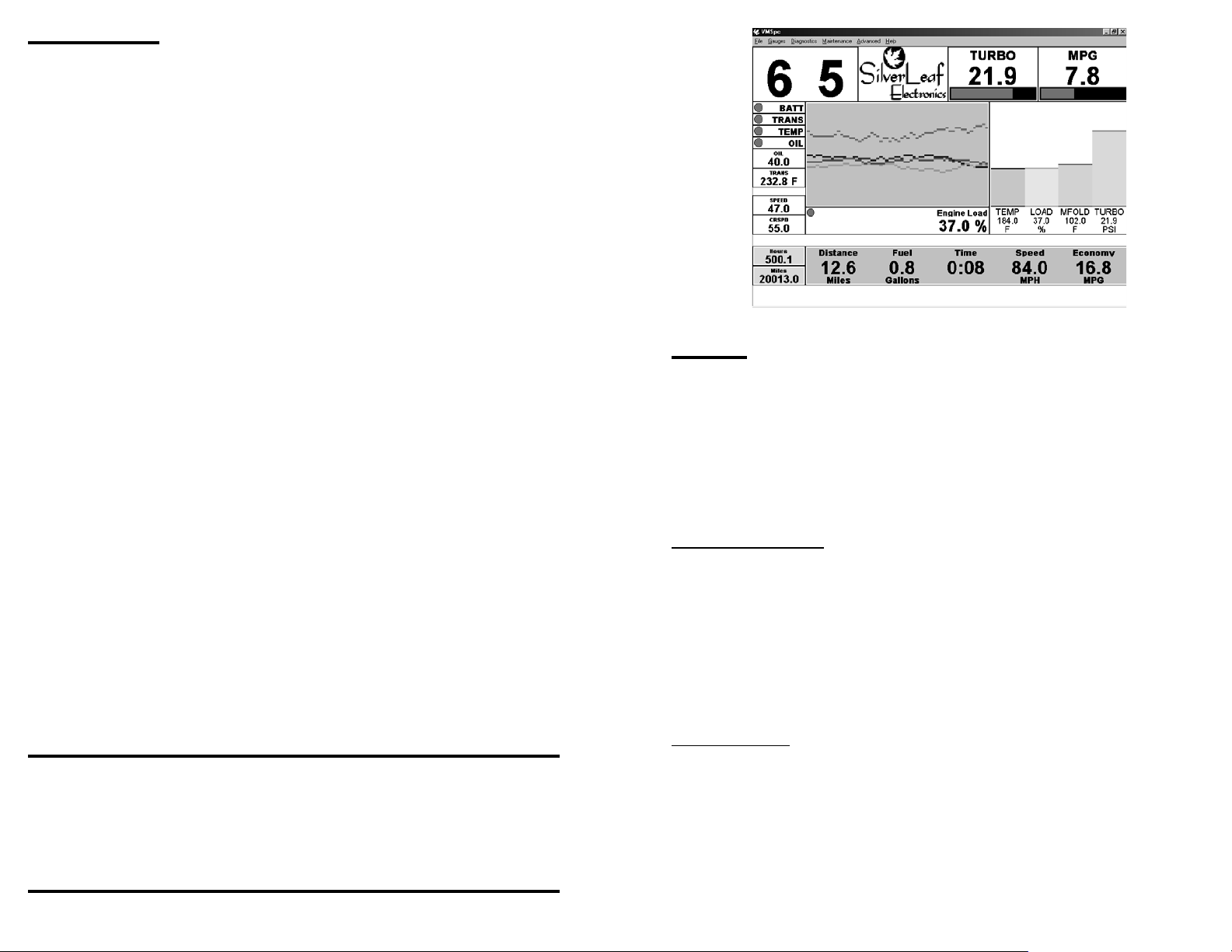
You can customize each gauge in a variety of ways. In the illustration above, most of
the gauges shown are varieties of the same type - the “Simple” gauge - but they have been
customized for a variety of effects. As you will see in the next section, the Simple Gauge can
be made to show just a warning light, a number, a bar graph, or any combination. Of course,
you also configure the gauge to show the data that you want - Coolant Temperature, Oil Pres-
sure, Battery Volts. All types of gauges are similarly customizable.
To customize a gauge, first click on the gauge with the left mouse button to select it.
How VMSpc Works
Today’s electronic diesel engines all feature a standard digital interface that was de-
signed for mechanics to be able to test and diagnose all kinds of engine issues. Each engine
builder provides special electronic tools to their technicians to tap into this special interface.
VMSpc uses the exact same technology - but it doesn’t take an trained technician to use it.
All of the readings you see on your screen are taken directly from the engine and trans-
mission. They are the most accurate readings available - period. If your dash gauge differs
from the reading in VMSpc - trust VMSpc first. VMSpc shows you exactly what the sensor
reads, with no loss of accuracy like an analog gauge.
How to Get Help
You can get help from SilverLeaf Electronics in several ways. Our web site features
a bulletin board for VMSpc users - if you have a question about VMSpc, someone else quite
probably has already asked it and we’ve posted an answer. The bulletin board is also where
VMSpc users swap their ideas and tips, and is a good place to learn more about the program
and your vehicle.
If you need direct help, call SilverLeaf at 888-741-0259, 7:00-4:00 Pacific Time, Mon-
Fri. We’ll be happy to help you.
If you have questions about the diagnostic information VMSpc is providing, please call
your engine or transmission manufacturer or chassis builder. Granted, the SilverLeaf staff is
pretty engine-savvy, but we are just computer jockeys, after all. We can’t do much to fix a bad
injector.
Free Software!
Watch our web site - as we continue to update the VMSpc software you can download
the new versions free of charge. New versions come out several times per year, and you are
always welcome to them. If you have suggestions for future versions, let us know by posting
them on the web forum. Your ideas are important to us.
System Requirements
Pentium 90 mHz or faster. 200 mHz recommmended.
Windows 95, 98, ME, NT, Win2000, XP, Vista, or Windows 7.
Mac OSX using Bootcamp, VMware Fusion, or Parallels to run Windows
16 MB RAM. 32 MB recommended.
1 MB hard drive space.
USB Port
Electronic Diesel Engine w/SAE Standard Diagnostics.
Although we have tested VMSpc with a wide variety of systems, we cannot guarantee
that it will work with every PC hardware and software combination.
Warning: We have designed VMSpc to be highly flexible and easy to use. We didn’t do this
so you could try to manipulate the program while you drive. If you feel the need to change
your layout or settings, reset your odometer, or check your diagnostics while you are driving,
DON’T! Wait until you are completely stopped, or have a passenger make the changes. Your
refrigerator is also useful and easy to use, but we don’t want you getting up to grab a tasty
beverage while cruising at 65 mph either.

67
Clock Sometimes it’s nice to know what time it is.
Message Box Groups of messages that you set to appear under certain condi-
tions. For example, you can program a "Hot Coolant Temp"
message to appear when the coolant temperature exceeds a
certain level.
Picture An ordinary bitmap picture. Not just for fun - you can use Pic-
tures and Text to mark important items and help the eye find key
readings quickly.
Text Anything you care to write. Put reminders like “Max Temp 225º”
where you like.
Tires If you have installed a PressurePro system, this gauge will show
status icons and/or the pressure for each tire.
Message Box Displays one or more text "messages" based on circumstances.
Saving Your Layouts
When you have the screen laid out the way you like, select “File” and “Save” - or if you
wish, “SaveAs”. When you start VMSpc, it automatically loads the last layout that you saved.
You can load a different layout by selecting “File” and “Open”.
Then click on it again with the right mouse button. Adialog box should appear presenting all
the many settings available for that gauge.
When you have finished customizing your layout, remember to select “File” and “Save”
or “SaveAs” to keep your changes for the next time you run the program.
Creating and Deleting Gauges
To create a new gauge, simple select “Gauges” from the main menu. Then select the
type of gauge you would like to create. The program will prompt you for details regarding how
you would like the gauge to be shown. Whe you complete your selectrions, the new gauge
will appear in the top left corner. Move the gauge where you want it, resize it as you desire,
and configure the gauge as described above.
To delete a gauge, click on the gauge with the mouse to select it, then press the Delete
key or select “Gauges” and “Delete Gauge” from the main menu.
Types of Gauges
The details of each gauge type will be provided in the following sections. Here we will
give a short summary of each type.
Simple Gauge The most common type. This displays a single data value, and
can show it numerically, as a bar graph, a warning light, or any
combination.
Scan Gauge Like a Simple Gauge, but this gauge can be configured to “scan”
through a list of parameters, every few seconds changing which
value it is displaying. This is a way to fit multiple gauges into the
same space.
Odometer This lets you track your fuel economy, mileage, and travel time
for each trip you take. Each Odometer also has a History file
where past trips are recorded. You may have as many Odom-
eters as you wish.
Tank Minder The Tank Minder is a handy tool for tracking your current fuel
level and distance to empty. You simply reset the Tank Minder
every time you refuel. The Minder keeps track of the fuel you
have left, and estimates how far you can drive until the tank is
empty.
Transmission Indicator (For 6-SpeedAllison “World” Transmissions Only). Shows the
Gear Selected and GearAttained for the transmission.
MultiBar Allows you to line up a series of vertical bar graphs.
Histogram Amoving graph useful for showing fluctating values. Particularly
valuable for managing coolant temperatures and fuel economy,
since it allows you to see the effect of changing conditions.
89
VMSpc automatically scales the text and graphics according to the size of the panel
and what items are being displayed. After making your settings you may wish to resize the
panel to get the text and graphic in the proportions you desire.
For Scan Gauges, a slider allows you to change the amount of time the gauge spends
displaying each item. If you have multiple Scan Gauges each can rotate at a different speed.
The fastest setting will cause the gauge to change every half-second. The slowest setting
changes it every 18 seconds.
Pressing the Change Color button allows you to change the background color of the
panel. This can help make particular gauges stand out for quick viewing.
Special Gauge Items
Most gauge items are self-explanatory, but some are unique to VMSpc.
Torque and Horsepower
These are calculated from various operating parameters, and are generally accurate
to within 5%. However, the proper engine must be selected in theAdvanced menu, under
Engine Type. These gauges are not intended as diagnostic tools.
Recent and Rolling MPG
Rolling MPG shows your fuel economy "right this minute", while Recent MPG shows
your fuel economy over the past twenty minutes. Both are useful tools for saving fuel.
Max Gauges
These gauges show the highest reading observed for the gauge over the last twenty
minutes.
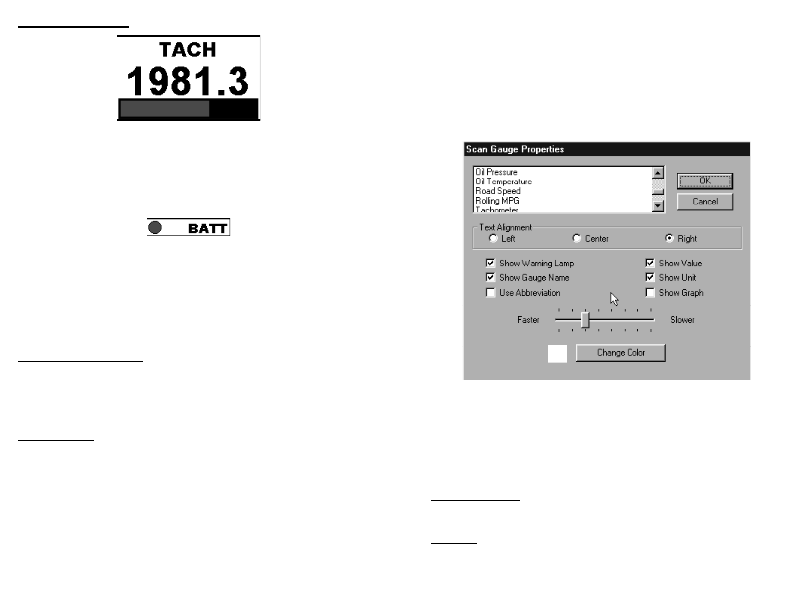
Simple and Scan Gauges
ASimple Gauge consists of a panel with up to four elements. At the top of the panel is
the name of the item being displayed and a warning “lamp” that changes from green to yellow
to red according to the status of the reading. The middle of the panel shows the value, and
the bottom of the panel is a bar graph that provides a “analog” reading.
Any of these items can be removed, and thus you can create a simple warning light
like the one below by removing the bar graph and main reading. You can even eliminate the
name if you wish!
AScan Gauge is almost identical to a Simple Gauge, but the parameter being dis-
played constantly changes, showing each of a group of items in turn. The items shown and
the speed with which it changes are both controlled by you.
Customizing the Simple and Scan Gauges
To customize the gauge, select it and right-click on it to bring up a dialog box like the
one illustrated. (The one shown is for the Scan Gauge. The Simple Gauge is almost identi-
cal, but is missing the Speed setting.)
Selecting the Parameter(s) Shown
The dialog box presents a list of possible gauges. Simply click on the item you wish the
gauge to display. With a Scan Gauge, you may click on as many items as you wish - each will
be highlighted. Clicking on an item again “unselects” it.
Note that not all engines support all potential gauge items. If a particular gauge always
reads zero, your engine simply does not support that feature.
Arranging the Gauge
The TextAlignment setting allows you to determine the horizontal position of the gauge
name and value.
Show Warning Lamp determines whether the green-yellow-red warning circle is dis-
played. If selected, the “lamp” will appear to the left of the title.
Show Gauge Name determines whether the name of the item is shown at all. If Use
Abbreviation is selected the name will be abbreviated - “TEMP” for “Engine Coolant Tem-
perature”.
If Show Value is not checked, the gauge will not show the numeric reading. Similarly
Show Unit determines whether the unit-of-measure (e.g. MPH, Volts) is displayed, while Show
Graph determines whether the bar graph is displayed.

10 11
Customizing the Odometer
Show Captions and Show Units determines whether the captions (“Speed”, “Economy”)
and the units (“MPH”, “MPG”) are displayed. Showing both is somewhat redundant, and you
can save space by eliminating one or both.
The Layout options include “Horizontal”, which lines the values up side-by-side, as
shown on the previous page, or “Vertical”, which lines the values up top-to-bottom. The Text
Alignment determines how the values are aligned - in the illustration they are aligned Left.
You may choose to show any, all, or none of the five values. You may also "Lock" the
odometer, which prevents it from being reset when you double-click on it.
Start From Day One
If you would like to create an odometer that shows the total history of the RV, select
"Start From Day One". Note that sometimes engines get "reset" while being serviced. In this
case the odometer will read the history since that service event.
Change Data File
This button allows multiple screen layouts to share the same odometer information.
Simply click on the button and select the desired .ODO file, using the same file in both layouts.
You can also use this to show the same odometer information twice on the same screen.
Hourmeters and “Conventional” Odometers
These two gauges here are not Odometers! To show an ordinary Engine Hourmeter
or Odometer (i.e. total engine miles), create a Simple Gauge and select the Engine Miles or
Engine Hours from the gauge list..
Odometers
An Odometer is a special gauge that totals the mileage, running time, and fuel usage
during the duration of a trip, and calculates the fuel economy and average speed. You may
have more than one Odometer running - many people use one to track the fuel consumed
from each tankful, another to track their trips point-to-point, and yet another to track each day.
Each Odometer maintains a history file. Each time the Odometer is reset, the informa-
tion is stored in the history file for future reference. You can add notes to the history file, such
as begin and end points and other comments.
Using an Odometer
When you create an Odometer, VMSpc starts by recording in a special file the engine
readings at the time of its creation. As you drive, it displays the difference between the current
engine readings and the stored values. When you reset the Odometer, the file is updated with
the current engine readings again.
This means that you do not have to have VMSpc running all the time for the Odometer
to work. You can unplug the JIB, drive a hundred miles, and plug back in. The Odometer will
“magically” show the correct mileage, time, and fuel usage for those hundred miles.
This also means that if you plug into a different engine, the odometer readings will be-
come confused. This isn’t a problem unless you mistakenly reset the odometer while plugged
into the other engine. And finally, the Odometer needs an up-to-date engine reading when
you reset it - the system does not actually have to be plugged in and running at the time, but
the last data it received should be up-to-date and from the proper engine.
The Distance and Fuel readings indicate the number of miles past and the amount
of fuel burnt. The Time is the actual elapsed running time from the engine. The Speed and
Economy measures are calculated from the distance, fuel, and time readings.
In early stages of a trip the Speed and Economy values will fluctuate wildly. The fluc-
tuations will quickly diminish, and within an hour the readings will be quite accurate.
Resetting and Viewing the History
To Reset the Odometer, select the Odometer, right-click on it, and the Odometer Prop-
erties dialog box will appear. Click on Reset Trip, and all the readings will be reset to zero.
Or, simply double-click on the Odometer (unless the odometer is "locked". See below.)
As noted above, make sure that VMSpc has up-to-date information from the engine
when you reset. VMSpc has a “memory” where it stores the latest readings from the engine,
so the engine does not actually have to be on at the time. But if VMSpc was plugged into
another engine, or the engine has been run without VMSpc being plugged in, then you should
not reset the Odometer until you can update the readings.
When you Reset the Odometer, the existing data is automatically stored in a text file.
This file can be viewed and edited by selecting View History. This will bring up the text file in
Notepad or your system’s default text editor. Notepad has its own menu, from which you can
print the file or cut-and-paste portions into another document or spreadsheet. You can also
add your own notes, such as the begin and end points of each leg, or anything else you wish.
Remember to click File and Save and then close the window when you are done editing.

12 13
Transmission Indicators
If you have a six-speedAllison “World” Transmission built between 1998 and 2006, then
VMSpc can show the Gear Selected and GearAttained. This feature requires their WTEC
IIIv8 electronics package, which was introduced in 1998 and can be identified by the fact that
the shifter only shows one number - the "Gear Selected" - and does not tell you what gear the
transmission is actually in.After 2007,Allison returned the GearAttained indicator to the shift-
ers. VMSpc still displays both indications as well.
This is one of the simplest gauges. You may choose to show either or both the Gear
Selected and the GearAttained. The Gear Selected will show “6” when you put it into “Drive”,
but it will automatically change when the engine brake is activated or if you press the Down or
Up arrows on the shift console. The GearAttained shows the gear the transmission is actu-
ally in.
Like almost all gauges, you can also adjust the text alignment and background color.
You may have multiple indicators, so you may choose to make a small “Gear Selected” indica-
tor next to a large “GearAttained” - just make two indicators and customize each accordingly.
Tank Minder
You can use a Tank Minder to provide an ongoing “Miles-to-Empty” reading that
estimates how far you can drive before your next refueling. You simply reset theTank Minder
every time you refuel. As you drive the Tank Minder tracks the engine fuel consumption, and
displays the estimated fuel remaining and an approximate distance you can expect to travel
before the tank is empty.
VMSpc has no way of reading the actual physical tank level, and it had no idea how
much fuel might be consumed by the furnace or generator. Therefore the Tank Minder should
be used with considerable caution. It always assumes the tank is filled completely, and that
only the engine is using fuel. If this is not the case, then the results will of course be incorrect
.
Setting up a Tank Minder is similar to an Odometer, but simpler. After selecting New
Tank Minder and positioning it on the screen, right-click on the Minder and set the Tank Size.
You can also customize the layout from this dialog box.
xc
If your tank is not completely filled, or you wish to compensate for fuel burned by other
devices, you can adjust the Current Level as needed.
Select “Calculate Using Recent MPG” if you wish the Miles-to-Empty value to be calcu-
lated using the current Recent MPG reading. If this is not checked, the Minder use the MPG
experienced so far on this tank of fuel. Using Recent MPG makes the Minder more respon-
sive to current conditions, which may or may not be desirable.
14 15
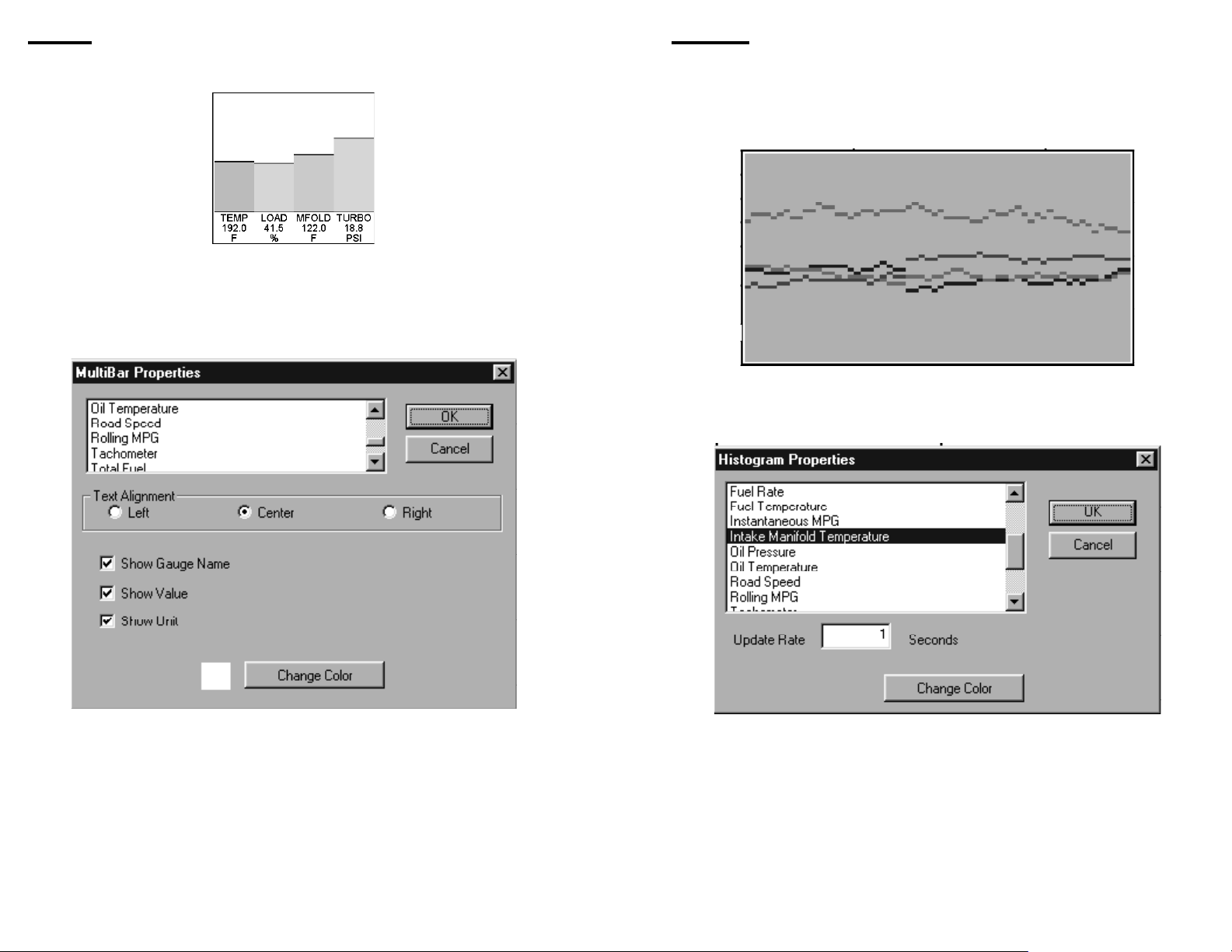
Histograms
AHistogram is a moving graph which helps show how values fluctuate over time. This
is a particularly useful gauge for managing temperatures during a hot, hard drive, since you
can see immediately how factors like Turbo Boost Pressure and RPMs affect your tempera-
tures. It is also useful for watching your fuel economy and the factors that affect it.
It is often a good idea to place a MultiBar next to the Histogram to provide a sort of
“legend” - if the same parameters are chosen for both, the colors will correspond.
The settings are few and simple. Right-Click on the Histogram to bring up the Histo-
gram Properties box. Select as many parameters as you wish to graph - there is no limit. The
Update Rate determines how much time passes between each “tick” - the graph shows 60
ticks. As with all gauges you can control the background color. The color of each graph item,
though, is automatically assigned.
MultiBars
AMultibar is an attractive way to display a number of values graphically.
The MultiBar is customized very much like the Scan Gauge. Right-Click on the gauge
to bring up the MultiBar Properties box. You may select as many parameters as you wish
from the list at the top of the dialog box. You may choose whether to display the Gauge Name
(the name is always abbreviated), the Value, and the Unit.
Like most gauges, you can adjust the TextAlignment and background color. The bar
colors are automatically assigned by VMSpc, and cannot be changed.
16 17
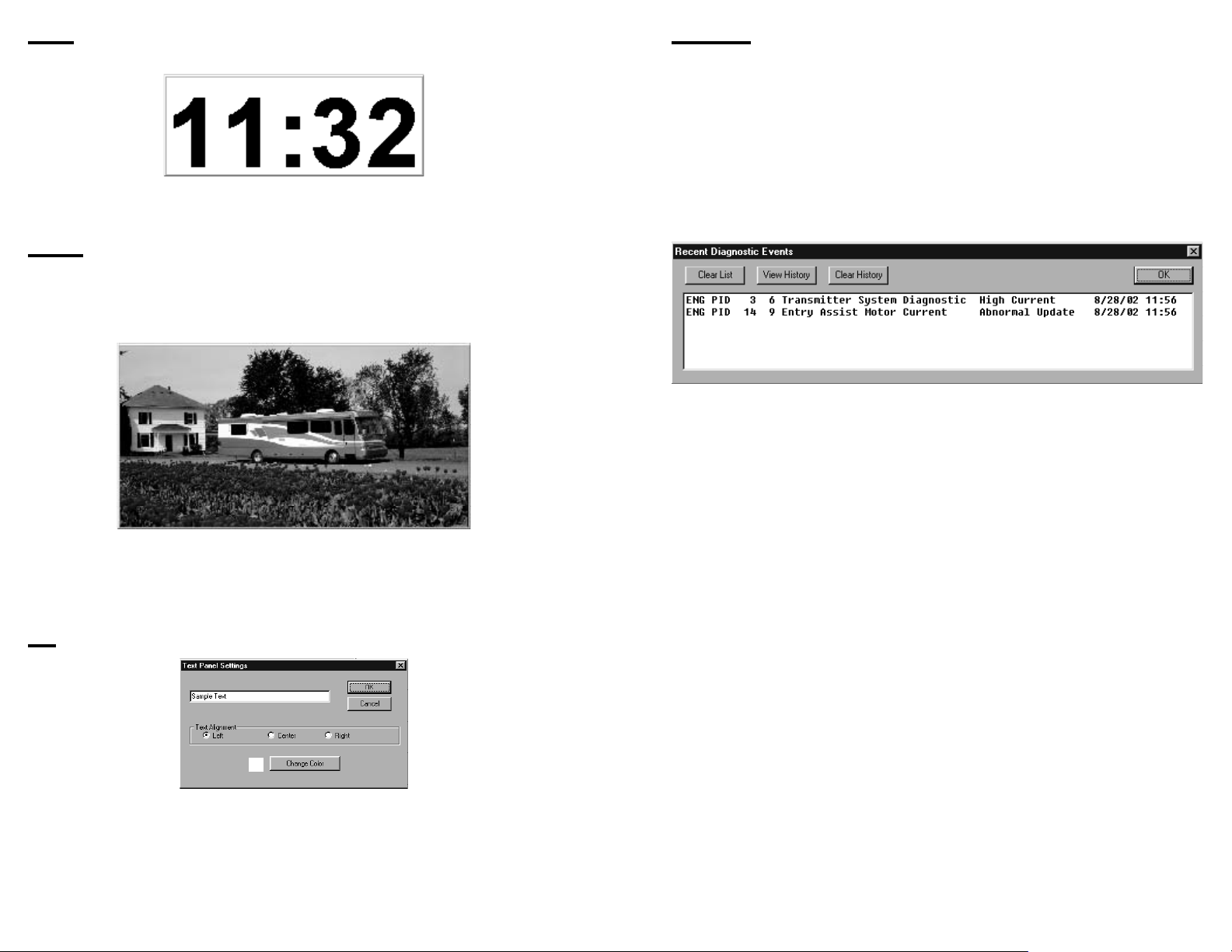
Diagnostics
One of the most powerful features of the modern electronic engines is their self-di-
agnostic capabilities. The engine ECM is capable of detecting a variety of problems, both
potential and actual. The ECM can report these problems to a service computer or VMS PC.
The Diagnostics dialog box allows you to view these codes and read what they mean in plain
English.
Select “Diagnostics” from the main menu to bring up the Recent Diagnostics Events
box. This box will show any problems that have been detected since VMSpc has been con-
nected to the engine and transmission. It also can show some past items, but this ability is
limited by the engine programming.
Each line of text shows a fault event. The first column shows the source (Engine,
Transmission, orABS Brakes). The next three columns are used by mechanics to find
information in their service manuals. The main part is the plain-language description, which
indicates the component that is malfunctioning and the type of malfunction. Finally, the date
and time of the first occurence is given.
If a fault repeats VMSpc does not show it again. (If it did, the list would quickly grow
out of control.) To determine whether a problem has disappeared, click on “Clear List” to clear
the box. If the fault occurs again it will appear again in the box, usually within a few seconds.
The diagnostic events are also stored in a text file for permenent reference. To view the
history file, click on “View History”. This will bring up the file in Notepad or your system text
editor. You can annotate the history if you wish, just as you can add notes to the Odometer
histories. Clicking on “Clear History” will clear the history file.
Remember that VMSpc is simply the messenger - it can only describe problems that
the engine or other components report. In the real world, the system correctly detects and
diagnoses the overwhelming majority of problems you might encounter. But the system is
limited in an important way.
Your chassis, including the engine, has a large number of mechanical parts. But the
ECM is purely electronic, and can only analyze what it can sense. So it provides very ac-
curate information on the fuel injection (which is typically entirely electronically controlled), but
less information on fuel flow, and no information at all about the fuel pump.
Thus VMSpc might show you that the fuel pressure is low. But it can’t tell you whether
that is because the fuel filter is plugged or the fuel pump is leaking.
Occasionally even engine designers make mistakes, and although bugs are rare, they
do occur. If you see anomolous readings or messages, consult the engine manufacturer or
appropriate component builder.
Clocks
The Clock simply shows the time, as provided by the PC system clock.
Other than being able to size it and place it whereever you desire, the only customiza-
tion available for the Clock is the background color.
Pictures
Adding a Picture gauge is a way to personalize your layout, and also can be handy for
creating markings to bring attention to particular items. Any Windows Bitmap file (“.BMP”) can
be put into a scalable window.
If you right-click on a Picture, rather than a Dialog Box for customizing the panel, you
will get a box that lets you load a new picture. There are no other settings available for a
Picture.
Text
AText gauge is another very simple gauge. It allows you to place a bit of text on the
screen - just one line at a time. This is a convenient way to place a reminder on the screen
such as “Max Temp 225º”.
18 19
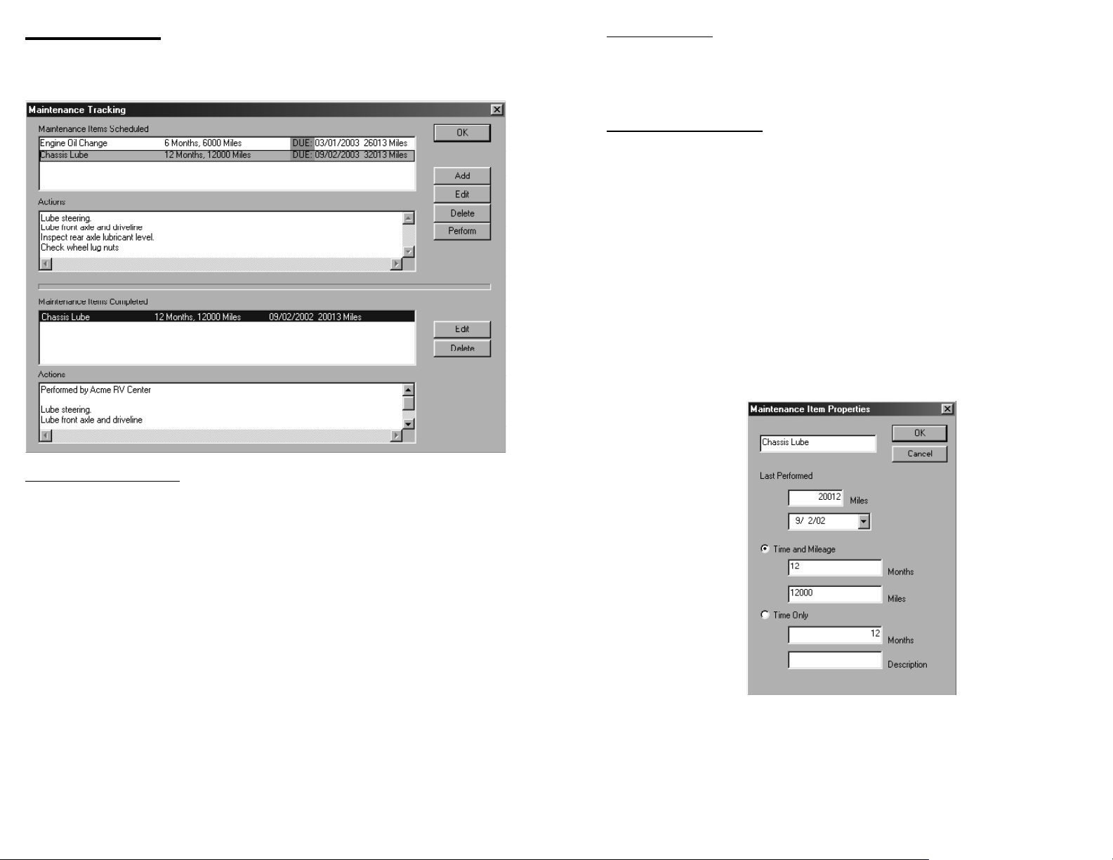
MaintenanceActions
With a maintenance interval highlighted, click in theActions window and enter each
of the types of services that will be routinely performed on the coach. For example, you might
define a “Lube” as: Lube steering, front axle and driveline, inspect rear axle lubricant level
and check wheel lug nuts. These items will become the master service list for this interval.
Maintenance Items Completed
When the coach has been serviced, select the appropriate interval from the Mainte-
nance Intervals Scheduled and click on Perform. This will create an entry in the Maintenance
Items Completed list. TheActions list will initially match the list from the Interval, but you may
edit this list to match the services completed on that day, and to add notes for your future
reference. This will only change the individual maintenance interval and not the list in the
Interval section.
VMSpc automatically records the date, time and odometer reading of the interval, then
updates the alarm in the Maintenance Interval section to account for the next due mainte-
nance. You can change the date and mileage in this section by clicking on the Edit button, but
this will not update the schedule at the top of the screen. To change the date due, select the
item in the Schedule section and click the Edit button in that section.
When you are done, click on Ok.
Maintenance Tracking
The Maintenance screen allows you to track your maintenance status. There are two
sections: Maintenance Items Scheduled and Maintenance Items Completed.
Create a Maintenance Interval
To track your maintenance schedules with VMSpc you will first need to manually input
each of the maintenance intervals designed for your chassis. This information should be
in your coach manual. To create a maintenance interval, click on theAdd button. Enter an
interval name, frequency and mileage for the repeating service interval. For example, Lube
at every 6 months or 6000 miles. You can also define an item as based on time only. You
also can enter a date and odometer reading when the item was last performed - the program
defaults to the current date and odometer reading.
Alarms will be set up for each interval set that will inform you when the next service is
due on your coach. These alarms are color signals that are similar to the ones used on the
Monitor page. They range from green to orange to red. Green indicating good status, yellow
indicating the service is due soon and red indicating that the service is overdue. VMSpc au-
tomatically calculates the next due service when a maintenance interval is created and each
time a service was performed.
The Edit button allows you to change the interval name, the months and mileage fields
relevant to the highlighted interval. If no interval has been selected, a new interval will be cre-
ated. The Delete button, removes the selected maintenance interval or maintenance history
item.
20 21
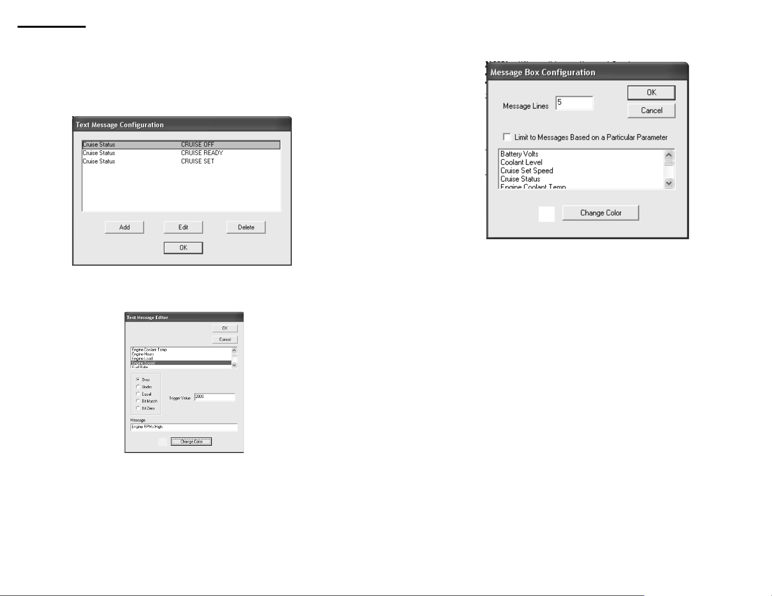
parameter such as Coolant Temperature or RPMs. Or you can create a single box shown all
the active messages in one location.
Select "New Message Box" from the "Gauges" menu.
If you wish to create a box that shows only certain messages, click the check box and
select the parameter desired. You will also probably want a single message line.
If you want a multi-purpose box, do not check the checkbox. But add message lines to
ensure that if multiple messages are active at one time, all will have space to appear.
Only the box background is affected by the color choice. The messages will all appear
in the color indicated in the Message Configuration.
Message Boxes
The Message Box feature allows you to define small text messages and make them
appear on the screen in various circumstances. For example, you can define a Message
Box to read "High RPMS" in yellow when the RPMs are over 2000, and "RPMs Ok" in green
otherwise.
It takes two steps to make such a Message Box. First, the Messages must be defined.
Select "Messages" in theAdvanced menu.
You may add new messages or edit exist ones. Select "Add", and a second box will
appear.
Choose the circumstances in which you would like the message to appear, the text,
and the background color for the message. In this particular case, two messages will have to
be defined - one for the High RPMs, one for the RPMs Ok. There is no limit to the number of
messages, and you may define messages based on any number of parameters.
Creating the Message Box
Once the messages are defined, you can create Message Boxes on the screen. You
may create several individual message boxes, each showing messages based on a particular
22 23
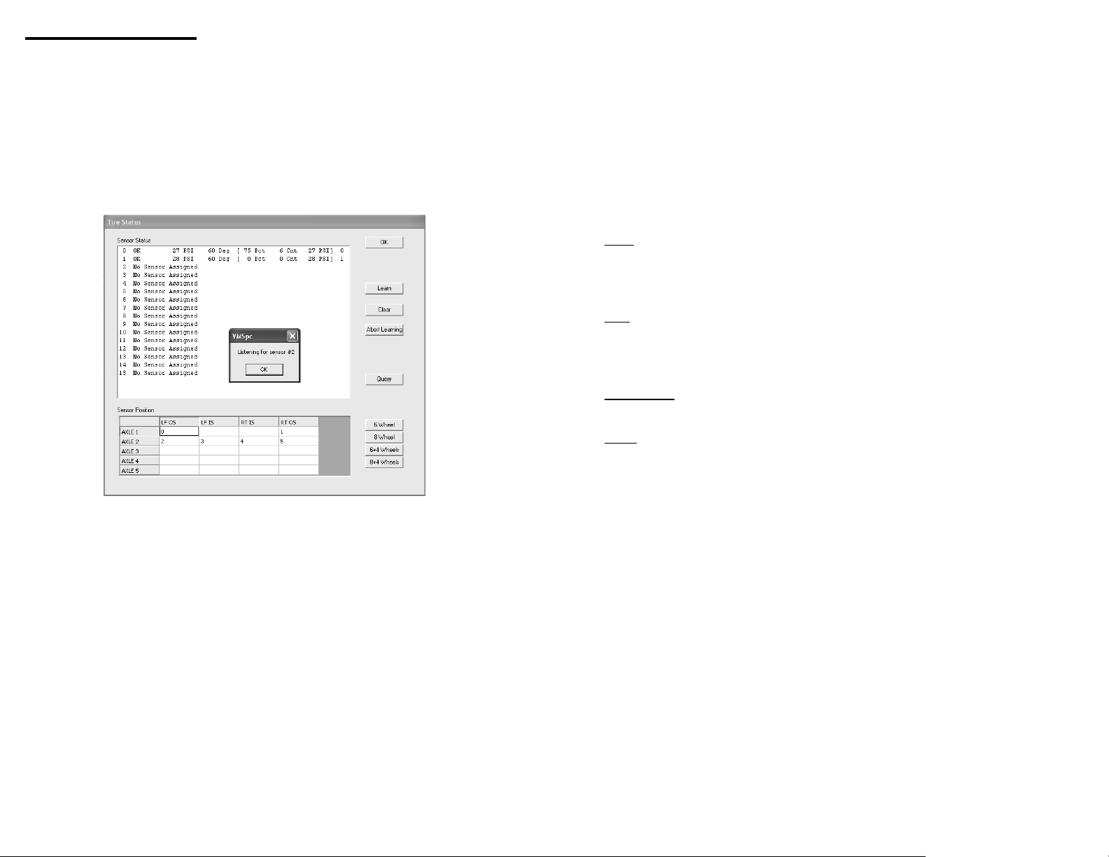
PressurePro Tire Monitoring
For information on installing the PressurePro receiver, consult the PressurePro Instal-
lation Manual. After installing the receiver you may follow the instructions in this section to
configure the display.
Tire Learning
The first step in configuring your PressurePro sensors is installing them on the stems.
As you do so, you will assign a number from 0 to 15. At this point the order is not critical, but it
will be easier to set up the display if you proceed in order from left fromt to right rear.
Select "Status" from the Tires menu. The Tire Status screen will appear.
To begin, click on Sensor 0 in the "Sensor Status" box, and click the "Learn" button.
Then install the sensor on the left-front tire. The system may require up to a minute to register
the sensor signal. Once it has registered and data appears in the Sensor Status window you
may repeat the process for the next sensor.
It may take up to five minutes to register all the data from a specific sensor. Once it
has all registered you can read more than just the tire pressure. Also available are a rough
temperature reading, the signal strength, a message count, and a target pressure. The last
number in a sensor ID used as a cross-reference when multiple monitors are installed.
The signal strength is expressed as a percent. Astrength of less than 40 indicates the
signal is too weak for reliable use, and you should consider moving the receiver or antenna
accordingly. The count indicates the number of messages received from the sensor, and it
should increment steadily over time.
Arranging the Tires
Once the tires are "learned", you may assign them to positions on the coach. The Sen-
sor Position table assigns the sensors to specific positions in the tire grid. If in the learning
process you worked from left-front to right-rear, you simply need to click on the appropriate
button on the right side and the program will automatically put the correct sensor assignments
into the grid.
Or you can manually enter the sensor positions into the grid. Simply insert numbers
from 0 to 15 in the grid to indicate which sensor is in each position. This will determine how
the sensors appear in the display gauge.
Tire Gauges
Once the tires are identified, you may create one or more Tire Gauges. ATire Gauge
can show circular icons indicating the status of each tire, or the actual pressure of each tire,
or both. You may have multiple gauges, perhaps showing icons in one part of the screen and
pressures in another.
The icons color indicates the tire status.
White This indicates no sensor is assigned to the position, but the position has been assigned
a sensor number. Check the Sensor Position grid in the Tire Status screen - a grid position
has a number for a sensor that hasn't been "learned".
Gray The sensor has not reported. This should disappear after a short while. If it remains
for more than a couple minutes then either the sensor has failed or the receiver can't pick up
its signal.
Red or Yellow
This indicates a pressure drop.
GreenThe pressure is Ok.
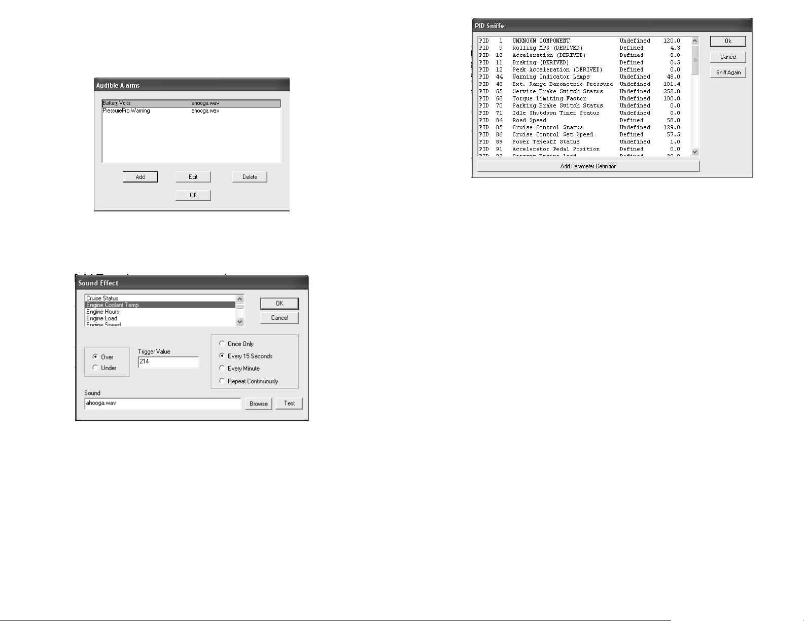
CreatingAudibleAlerts
If you want your PC to make noises when errors occur, you may create anAudible
Alarm based on the tire status. This requires several steps.
First, with the PressurePro receiver hooked up and powered, enter the PID Sniffer,
described in theAdvanced Features section of this manual. You should find a PID 501, "Pres-
surePro Warning", listed. Double-click on that line, which will create a PressurePro Warning
parameter that you can display.
Second, set up anAudibleAlarm using the process also described in theAdvanced
Features. Based the alarm on the PressurePro Warning parameter. This parameter will take
a value from zero to three, wich the following meanings: 0 =Asensor has not reported, 1 =All
Ok, 2 =At least one sensor is in a "yellow" pressure, 3 =At least one sensor is in a "red" pres-
sure range. Thus, to get an alarm for a RedAlert, set the alarm to trigger on a value greater
than 2.5.
In addition to theAudibleAlarm, you can get a warning icon which will turn greem, yel-
low, or red according to the overall status by creating a Simple Gauge based on the Pressure-
Pro Warning parameter.

24 25
Advanced Features
Wallpaper
Just as you can put a “wallpaper” in the background of your Windows desktop, you can put
any bitmap image you wish in the VMSpc background. Selecting “Advanced” and “Wallpa-
per” brings up a File Open dialog box which lets you choose any standard Windows Bitmap
(“.BMP”) file you wish tWallpaper
Just as you can put a “wallpaper” in the background of your Windows desktop, you can
put any bitmap image you wish in the VMSpc background. Selecting “Advanced” and “Wallpa-
per” brings up a File Open dialog box which lets you choose any standard Windows Bitmap
(“.BMP”) file you wish to display. VMSpc automatically scales the picture to the size of the full
program window.
Torque and Horsepower
The Torque and Horsepower parameters are unlike any others - they are the result of a
calculation based on various other parameters. To get an accurate reading, you must select
the appropriate engine so the values are calibrated properly.
Select “Advanced” and “Engine Type”, then select the engine file that matches your en-
gine. If your engine does not appear in the list, contact SilverLeaf Electronics for an update.
The Torque and Horsepower gauges are limited in the RPM range in which they work.
At very low or very high RPMs the value will read zero.
Data Logging
This feature allows you to create ongoing data log files that you can load into a spread-
sheet and use to analyze vehicle performance in great detail.
To create a log, select “Advanced” and “Data Logging” to bring up the Data Log Set-
tings dialog box. Select the items you wish to track in the parameter list - you may select as
many as you wish. Select a time interval between entries - each entry will be one line in the
log file. Give the log file a name - you can click “Select File” to bring up a file dialog box and
select an existing file graphically.
Finally, click “Start”. You can then select Ok and watch the main VMSpc screen - the
program will log the data whether or not this box is being displayed. To end the logging, open
the box again and click “Stop”.
You can view your log file by clicking “View Log”. The log file is a simple text file, with
each entry being a single line within the file. The most recent entry will be at the end of the
file. Clicking “Clear Log” will clear out the file to prepare it for another try. If you don’t click
“Clear Log”, you can have multiple runs in a single file.
There are several ways to get this raw data into a spreadsheet, and the precise direc-
tions vary from program to program. Many programs allow you to simply cut-and-paste the
data. Click on “View Log”, then in the editor menu select “Edit” and “SelectAll”, then “Edit”
and “Copy”. In your spreadsheet, select “Edit” and “Paste”.
If your spreadsheet doesn’t parse the data into columns as you expect, you may need
to the program’s Import procedures. This procedure varies considerably from program to
program. But the key fact you need to know is that the VMSpc output is a “Comma-Delimited
ASCII” file.
You can also set the unit to start data logging whenever you start the program, and
to only log data when the engine is running. Two check boxes allow you to select these
items. If you opt to have logging begin automatically, the log will always be recorded in
"DefaultLog.txt".
Raw Log
The Raw Log feature is an advanced troubleshooting tool designed to allow expe-
rienced technicians to diagnose certain kinds of problems. This feature creates a disk file
containing raw vehicle data that can be analyzed with the proper software. It has no other
purpose, and should generally be ignored.
Engine Corrections
Generally the data displayed by VMSpc is extremely accurate. But an improperly
calibrated engine may send speed, distance, and fuel information that is consistently wrong.
For example, if you put larger or smaller tires on the coach, the speed and odometer data will
clearly be incorrect.
To compensate for this kind of error you can enter correction values in the Engine
Corrections dialog box. For the odometer, hourmeter, and fuelmeter you can enter both an
“Offset” and a “Multiplier”. VMSpc will automatically add the Offset to the indicated meter,
then Multiply the result by the multiplier. In addition, the multiplier will be applied as appropri-
ate to the Speed, Cruise Speed, MPG, Fuel Rate, and Rolling MPG gauges.
For example, if your engine was reprogrammed and lost its history at the 20,000 mile
mark, and you added tires that cause it to understate the speed by 5%, change the Odometer
Multiplier to 1.05. Change the Offset to 19,408. (Remember that the Offset is added, then the
Multiplier is applied. 19,408 * 1.05 = 20,000.)
In addition to the engine corrections, this option also allows you to adjust the sensitivity
of the Rolling MPG reading. By placing a larger number in the “Rolling MPG Buffer Size” you
can increase the time window used for calculating the Rolling MPG, thus making it respond
more slowly. Alower number will make it respond faster, making the gauge fluctuate more.
The Odometer PID setting is intended for the few engines which do not report their
odometer readings with PID 245. If your trip odometers and other features do not report cor-
rectly, you may need to change this value from 245 to 244.
26 27
AudibleAlarms
You can configure your PC to make various sounds when a parameter exceeds a de-
sired level. You may define any number of such alarms, based on any gauge. To get started,
selectAudibleAlarms fromtheAdvanced menu. SelectAdd, and define your first alarm.
Choose the parameter and trigger value, whether the alarm sounds when the parame-
ter is over or under the value, and how frequently the alarm should sound. For the sound you
can use any “.WAV” file - there are a great many defined in the Windows Media directory.
You may define more than one alarm based on a parameter. For example, you may
create a series of escalating alarms based on, say, Road Speed. At 65 MPH set an alarm to
sound OnceOnly. Then at 75 MPH set an alarm to sound Every 15 Seconds.
You cannot delete an alarm while it is sounding.
PID Sniffing
Not all engines are alike. While almost all engines will have the main gauges you
might wish to monitor, there are many variations in the specfics. To take advantage of the full
capabilities of your engine, you can query it using the PID Sniffer.
When you select PID Sniffer from theAdvanced menu, a box will appear displaying
a list of engine sensors and parameters. The first column shows the PID identifier, then a
description appears. The third column indicates whether the parameter has already been
defined in VMSpc. Before you can create a gauge in VMSpc, the parameter must be defined.
If a parameter is undefined, you can attempt to automatically define it by double-clicking
on the parameter, or selecting the parameter and clicking on the "Add Parameter Definition"
button. If VMSpc knows how to define the parameter, it will do so and you may then create
gauges using that parameter. In some cases VMSpc will not know how to define the param-
eter and it will inform you accordingly. If you know the relevant information, you can manually
define a parameter using the Parameter Editor.
After defining a paremeter, you can adjust its properties - name, limits, abbreviation,
and numeric format - using the Parameter Editor. This is explained in detail in a later section.
If a parameter does not appear in the PID Sniffer, then your engine and/or transmission
andABS does not support it. Some parameters are labeled "Derived". This means that they
are calculated by VMSpc based on other data. For example,Acceleration is derived from
Road Speed.

28 29
Communications
Selecting “Advanced” and “Communications” on the main menu brings up the Commu-
nication Settings dialog box.
There are only two user settings here. The
Port allows you to choose the port address for the
J1708 Interface Board (“JIB”). The JIB Model indi-
cates the type of JIB you have attached. The JS500
was sold from 1999 to 2009 and uses a 9-pin serial
connection. The JS501 was sold from 2009 on, and
uses a USB connection.
If you press "Scan for JIB Connections", the
program will check your computer for possible JIB
devices. It will present a list of connected devices
for you to choose from, and will then automatically
adjust the port settings according to your choice. If
your JIB does not appear on the list, you probably
have not correctly installed the device drivers.
If you have a USB JIB, there are several
additional settings intended for dealing with specific
non-standard engines.
The Status reading indicates the current
communications status. When you change ports, or
first start VMSpc, it will read “Starting”. Within a few
seconds it should change to one of the following:
Ok Good news! VMSpc is receiving vehicle data.
PC Port Failure
VMSpc can’t open the indicated port. It doesn’t exist, or another
program has claimed it for itself.
Failure Between JIB and PC
VMSpc found the port, but no data is coming from the JIB.
Check to see whether the LEDs on the JIB are lit, and that the
PC cable is tight.
Failure Between Engine and JIB
VMSpc found the JIB, but the JIB is not getting data from the ve-
hicle. Make sure the key is on, and the engine ECM has power.
Set theAutoRestart flag if you have problems with the PC shutting down the communi-
cations port intermittently.
Parameter Editing
If you are not satisfied with the red-line and yellow-line settings for the many param-
eters that VMSpc tracks, you have the option to change them yourself. You can also delete
parameters from the list if your engine does not support them, and change their names and
abbreviations.
All this is accomplished through the Parameter Editor found in theAdvanced menu.
Selecting this menu item opens a box. At the top is a list box with all of the various param-
eters. When you select one, the rest of the boxes are filled with the appropriate values for that
gauge. You may change them as you wish.
The first item is the Gauge name, which is both how the gauge is shown in the list box
and also in the Simple and Scan gauges unless the display is abbreviated. TheAbbreviation
shows how the name will appear in the MultiBar and in the Scan/Simple Gauges when the
name is abbreviated. The Unit is the unit of measure shown in those gauges. Note: Chang-
ing the Unit does not change the display value. Calling Speed “Kilometers” won’t cause the
values to be converted to metric.
The Gauge Minimum and Maximum determine the boundaries for the bar graphs and
histogram. The Low Red and Low Yellow Lines indicate that if the value is below those levels,
the warning indicator in the Scan/Simple Gauges will show the corresponding color. Similarly
the High Red and High Yellow Lines determine when the indicators change with rising values.
The PID refers to the Parameter Identifier, and should not be changed, ever. It deter-
mines how the data is extracted from the vehicle data stream, and if incorrect the gauge will
no longer work.
The Offset and Multiplier allow you to make corrections, and incidentally also provide a
method for forcing VMSpc to show metric values. VMSpc adds the Offset, then multiplies by
the Multiplier to get the value it displays. For example, to change the Manifold Temperature to
metric, set the Offset to -32 and the Multiplier to .4545.
The Format allows you to change the precision with which the value is displayed. By
default all parameters are set to “%.1f”, which shows one decimal point of precision. To show
a parameter as a whole number, change this to “%.0f”.

30 31
AFew Tips and Ideas
Here are a few ideas for getting the most value from VMSpc. Some come from the
seminars we give at RV rallies across the country, some are ideas posted on our web site by
VMSpc users. For more ideas, check our user forums at www.simply-smarter.com.
Intake Manifold Temperature
The most important gauge in the system might be this one that few people even know
about. Intake Manifold Temperature measures the heat between the turbocharger and the
engine block, and is the single best indicator of how hot your engine really is. The manifold
gets hot well before the coolant gets hot for two reasons - first, the manifold is next to the
turbocharger, which generates most of the excess heat, and second, it doesn't usually have a
radiator constantly cooling it down. So this reading gives you an "early warning" for overheat-
ing. Also, the manifold keeps showing the heat contained in the engine block much longer
than the coolant, so it shows the heat build-up much better in variegated terrain.
There is no particular "red line" for the manifold temperature. But you can quickly learn
the normal range for your engine and set alarms accordingly.
Audible Checklist
Use an inexpensive microphone - your laptop might even have one built-in - to record
a list of things to check before you drive. Then create an audible alarm set to run once when
the Engine RPMs exceeds 500 rpms. Whenever you start the engine, the checklist will play.
Cruise Status Message
Most cruise controls don't tell you when the cruise is actually engaged, only that it is
"on". You can create a gauge to show you as much in several ways, and here's one.
Create three Messages, each based on Cruise Status. Call one "Cruise Off", and set it
to "Bit Zero", with Trigger Value 1. Call one "Cruise On", and set it to "Bit Match" with Trigger
Value 1. Call the third "Cruise Set", and set it to "Over", with Trigger Value 127.5. Give each
one a distinctive color, as well.
Then create a Message Box, with two lines, and limited to Cruise Status.
Using VMSpc with a GPS Program
VMSpc works fine side-by-side with most GPS programs such as Delorme StreetAtlas
and Microsoft Streets and Trips. Since VMSpc lets you arrange the screen any way you
please, but the GPS programs generally don't, the best way to set up the system is this:
Size the GPS window
Most programs only let you size the window, but not arrange the contents within. Find
a set of dimensions for the GPS window that provides a good map, but doesn't fill the entire
screen.
Arrange the VMSpc screen
Now, start VMSpc and arrange the most important gauges in the area of the screen not
being used by the GPS. Use the space that the GPS uses for items like historical odometers
that you usually do not watch while driving.
When you start driving
Start VMSpc first, then the GPS program. The GPS program will appear in front of
VMSpc. If you accidentally click on VMSpc it will take over the full screen. PressALT-TAB to
get the GPS back into view.
Using a USBAdapter with a JS500 Serial JIB
If your laptop does not have a standard serial port, you will need a USB-to-Serial
adapter to use the JS500 Serial JIB. For the details on installing the adapter consult the
instructions that come with it. However, there is one key point to emphasize when you use
these adapters.
When Windows sees a serial USB device, it assumes that it is a mouse. This is a
known "feature" of Windows that has been present since the invention of the Microsoft USB
Mouse. This means that under certain circumstances the computer will think that your engine
is a mouse, with predictably unfortunate consequences.
To avoid this problem, always start VMSpc and plug in your adapter in the following
sequence.
Start with the USB adapter unplugged on both ends.
The key is that no data should enter the adapter from the engine side until we have
taken control of the USB port.
Plug the USB adapter into the PC.
You should hear a little music as Windows realizes that something is plugged in. But at
this point we need to make sure no data is coming through the adapter.
Start VMSpc
The program will now "claim" the USB adapter as its own. This will prevent Windows
from making the engine into a mouse.
Plug the USB adapter into the Engine JIB
It is now safe to plug the adapter into the interface board and begin monitoring the
chassis.
If your JIB is wired to the ignition switch, you can start with the adapter plugged into the
JIB, as long as the key is off. Do not turn the key on until after you have started VMSpc.

32
Warranty
The obligation of SilverLeaf Electronics, Inc. under this warranty shall be limited to
repair or replacement (at our option) during the warranty period of any part which proves
defective in material or workmanship under normal installation, use, and service, provided the
product is returned to SilverLeaf Electronics, Inc.. The warranty period shall be one year from
date of purchase of the product.
This warranty shall be invalid if the product is damaged as a result of defacement, mis-
use, abuse, neglect, accident, destruction, alteration, improper electrical voltages or currents,
repair or maintenance by any party other than SilverLeaf Electronics Inc. or an authorized
service facility, or any use violative of instructions furnished by us.
This one-year warranty is in lieu of all other expressed warranties, obligations, or liabili-
ties. Any implied warranties, obligations, or liabilities, including but not limited to the implied
warranties of merchantability and fitness for a particular purpose, shall be limited in duration to
the one-year duration of this written limited warranty.
In no event shall SilverLeaf Electronics, Inc. be liable for any special, incidental, or
consequential damages for breach of this or any other warranty, expressed or implied, what-
soever.
This warranty gives you specific legal rights, and you may also have other rights which
vary from state to state.
SilverLeaf Electronics, Inc.
2472 SW Ferry St. • Albany, OR 97322 • (888) 741-0259
www.silverleafelectronics.com
Table of contents


