7700 MultiFrame Manual
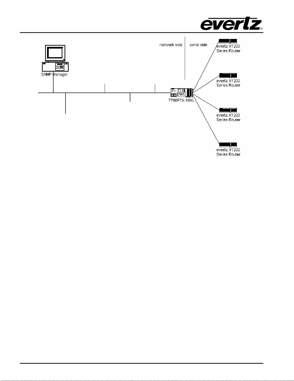
7700PTX-10XL Network-Controlled Protocol Translator
Revision 1.9 7700PTX-10XL - I
TABLE OF CONTENTS
1. OVERVIEW..................................................................................................................................... 1
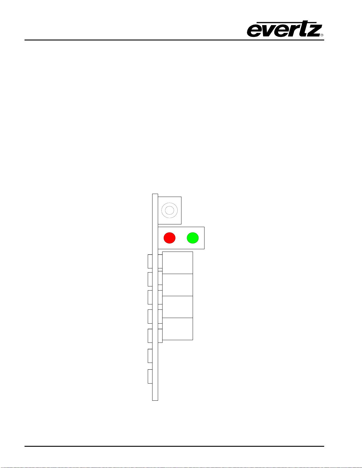
2. CARD EDGE CONTROLS..............................................................................................................4
2.1. DETERMINING CURRENT IP ADDRESS SETTINGS.......................................................... 4
2.2. RESTORING FACTORY DEFAULTS.................................................................................... 4
2.3. CARD EDGE LEDS ............................................................................................................... 4
3. TECHNICAL SPECIFICATIONS..................................................................................................... 5
3.1. DATA INPUT SERIAL PORT................................................................................................. 5
3.2. ELECTRICAL......................................................................................................................... 5
3.3. PHYSICAL ............................................................................................................................. 5
4. CONFIGURATION.......................................................................................................................... 6
4.1. CONFIGURATION STEPS .................................................................................................... 6
4.1.1. Master Mode...............................................................................................................6
4.1.2. Slave Mode.................................................................................................................6
4.2. DEBUG/MONITOR PORT CONNECTION............................................................................. 7
4.3. MAIN MENU........................................................................................................................... 9
4.4. NETWORK CONFIGURATION.............................................................................................. 9
4.5. SERIAL PORT SETUP ........................................................................................................ 10
4.5.1. Parameters ...............................................................................................................10
4.5.2. Back Plate.................................................................................................................10
4.5.3. RS-232 Wiring........................................................................................................... 11
4.5.4. RS-422 Wiring........................................................................................................... 13
4.5.5. GPO Common Pin Wiring......................................................................................... 14
4.5.6. GPO to GPI Wiring.................................................................................................... 14
4.6. SNMP SETUP......................................................................................................................15
4.7. 10XL PROTOCOL CONFIGURATION ................................................................................ 15
4.7.1. Master Mode.............................................................................................................15
4.7.2. Slave Mode...............................................................................................................15
4.7.3. Number of Router Inputs........................................................................................... 16
4.7.4. Number of Router Outputs........................................................................................ 16
4.7.5. Input & Output Descriptions......................................................................................16
4.7.6. Serial Address...........................................................................................................17
4.7.7. Power On Reset Router Initialization........................................................................17
4.7.8. Save & Exit ...............................................................................................................17
4.8. UNDER MONITOR DISPLAY SETUP ................................................................................. 18
5. TROUBLESHOOTING TIPS......................................................................................................... 19