SilverLeaf Electronics VMS 350 User manual

VMS 350
6-Button
Owners Manual
Getting Started
Automatic Video Mode
Whenever the linkers are on, or when the
coach is in Reverse, the unit automatically
switches from (key oard options) to the all-
video display mode.
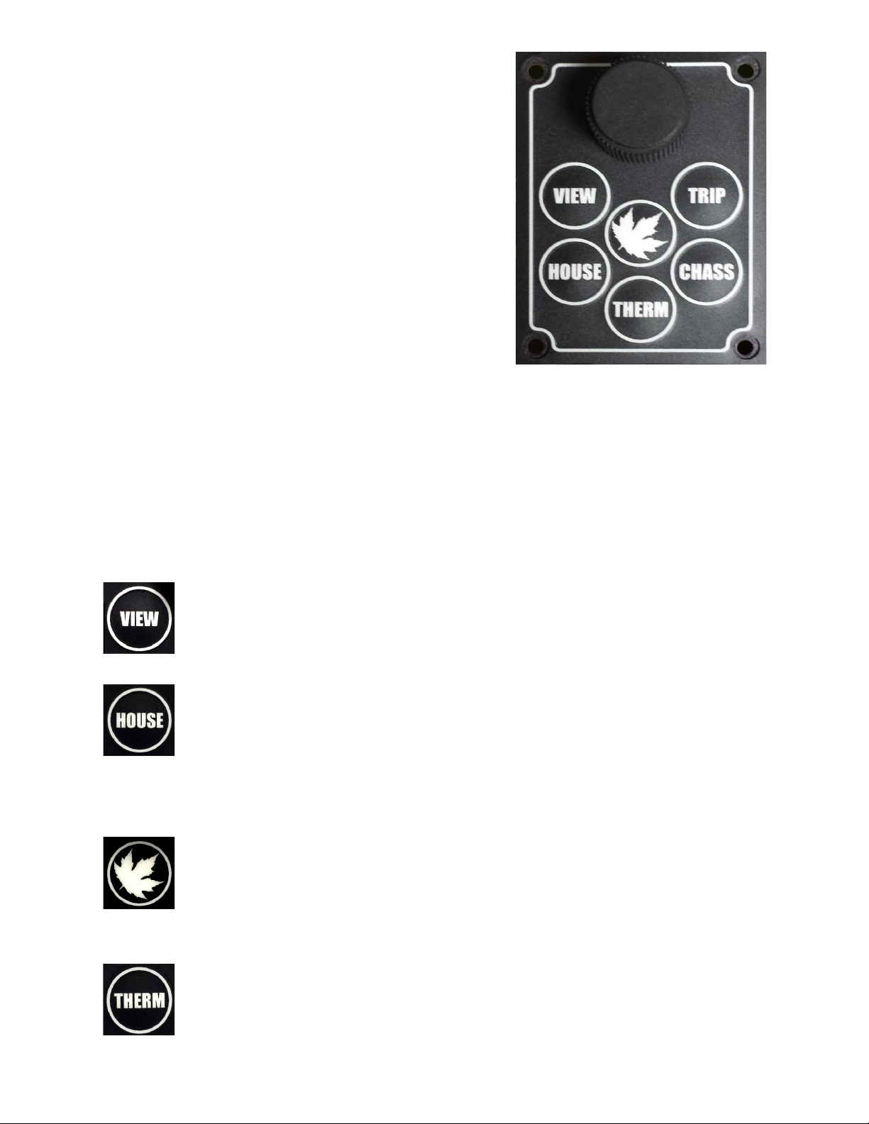
The VMS 350 Key oard
The VMS 350 is controlled y a small key oard. The large kno can e
turned left or right and is also e pressed. Think of this kno as eing
the “mouse” pointer for the computer – it's the main way one provides
input into the system.
The keys all have specific functions as riefly shown here. Expanded
details egin on page 8. While the VMS-350 is quite versatile, only the
installed options will e accessi le, ased on your units' configuration.*
View
Pressing this changes screen display; either vehicle information,
camera image or oth. Pressing it repeatedly cycles through the
3 different viewing modes.
House
This key cycles through the set pages of house data to include
the Installed Tanks, Generator, AC and DC Power and Floor
Heat monitors.* [For Forced air HVAC, See THERM.] These pages are
descri ed later in this manual and include configuration settings,
eginning on page 5.
Home
This key always returns the system to it's “home page”. This
key overrides all other keys to return the system to the main
gauge screen. A second press enters the Configuration screen and is
covered in depth later on.
Therm
This key enters the heating, cooling and ventilation pages.
2
Chass
This key enters into the three sets of helpful chassis screens.
These are the Tire Pressure page(s)*, Chassis Statistics and
Metrics on the Second page, and Diagnostics on the Third.
Trip
This key presents current trip statistics and the a ility to reset
or view prior trips.
The Cursors
Turning and pressing the kno controls the “cursor” icon on the screen.
The cursor has two modes. Pressing the kno switches the cursor from
one mode to the other.
Navigation
When the cursor has a triangular shape, turning the kno will
move the cursor up or down the page.
Adjustment
When the cursor looks like an arrow pointing at its tail, turning the
kno will adjust the setting the cursor indicates.
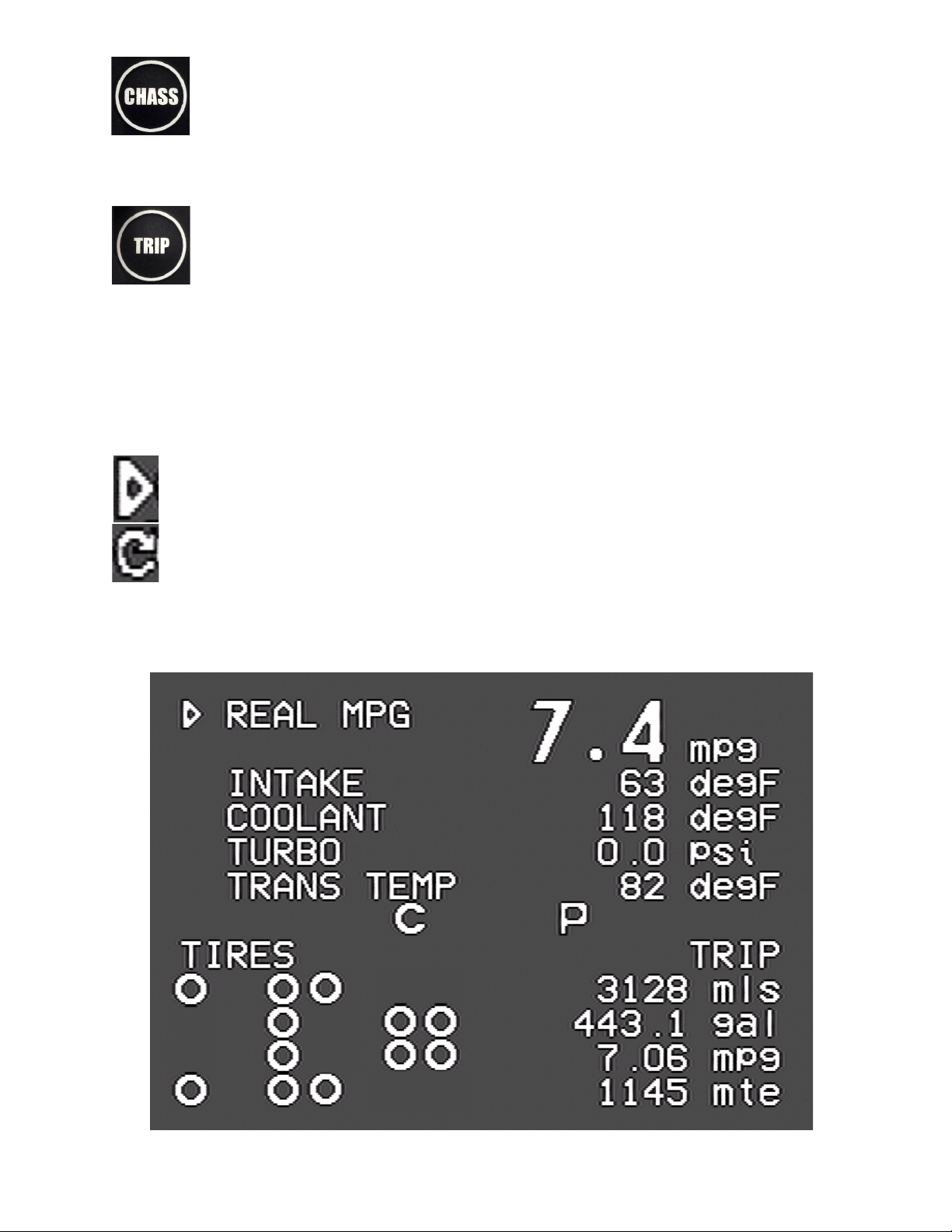
Home Screen
3

Home Screen
This screen displays the most popular and important features at
one glance. The screen has two pages or sections; Gauges and
Configuration Management. First page one lands at is Gauges
which include Status.
Gauge Section (upper)
The top portion of the screen displays five different engine and
transmission parameters per 'page.' Three unique pages then allow for
a static choice at the top, such as SPEED, and four others elow it.
Use the kno to change which items to display y turning the kno ,
selecting a gauge and pressing it. Turn the kno again to select another
gauge, then press the kno to complete the selection.
Note: Due to variations in engine configurations, some of the gauges
included in the VMS 350 may not e supported.
Whereas most of the gauges are read directly from the engine and
transmission, a few gauges are unique to the VMS 350. In particular,
the
Recent MPG
and
Real MPG
are special data items calculated y the
VMS 350 to help get the est possi le fuel economy.
Real MPG
shows the fuel economy over roughly the last minute or so,
and is intended to allow for adjusting driving technique to realize etter
fuel economy with headwinds and hills.
Recent MPG
shows the fuel
economy over a much longer period, and provides a good indication of
when driving strategy is working overall.
Near the center of the screen are Temperature and two icons. The
latter indicate the status of two key driving parameters:
Temperature: ---°F relates the am ient outside air temperature (when
a sensor is installed.) Dashes indicate sensor/ wiring malfunction or not
detected.
When the cruise control is On ut not Set, it displays as a
small 'c'. When the cruise control is Set, it ecomes a large
'C'. If no icon is present, Cruise is off.
4

The
Transmission Mode
icon indicates whether the
transmission is in “Performance” or “Economy” mode y
displaying letters P or E. The mode can e changed y pressing the
“mode” key on the shifter pad. Driving in “Economy” mode, all the time,
significantly improves fuel economy at no loss of performance.
Tire Section (Lower)
When Tire sensors are installed a map is shown. It's irds-eye view as
though coach is driving to the left. See pg.9 for details on
Temperature, Pressure, Leaks and Faults regarding individual tires.
This icon indicates that no pro lem has een detected with this
particular tire.
This Caution Icon indicates that the pressure in the tire may e
elow the set point for the monitoring system in use. For
PressurePro, it's 12.5% lower than than target. For Valor, it
represents a lower-than-set-point--as programmed y the coach
manufacturer. It can also mean the sensor attery is low or the sensor
temperature is overly hot.
This Warning Icon indicates the tire may e significantly elow
target. For PressurePro, this may indicate a pressure 25% elow
the target. This will also trigger an audi le uzzer which will uzz until a
key (any key) is pressed or the kno is turned.
Note that the target pressure is the pressure detected (or programmed
in) when the tire sensor is installed on the tire. For more details, see
the Tire Screen section. PressurePro models may e configured there
ut Valor cannot and must e factory serviced.
This icon indicates that no data has een received from the
indicated sensor. If this icon persists for more than a few minutes
the sensor should e checked.
To check the actual tire pressures and to get additional detail, press the
Detail key until the Tire Screen appears. See elow for more
information.
5

Important Notice
Electronic Tire Sensors, when installed, transmit the individual tire
pressures to the Monitor via Radio Frequency (RF) signals which can
then e displayed in real-time. PressurePro Sensors read tire pressure
every 7 seconds and transmits the updated readings to the Monitor.
Some of these transmissions will e interfered with. Because of this
nature of RF no guarantee of signal reception can e made. PressurePro
is not meant to function as a precise pressure gauge or a low pressure
indicator. PressurePro is a tire pressure monitoring system that
displays tire pressures and which, when a signal is received, will signal
low pressures.
Configuration Screen
This screen appears with a second kno -press. It allows for adjusting the
time and date, view engine diagnostics and other details, and access
other features of the VMS 350.
6

Adjusting the Time and Date
Turn the kno to point the cursor at either the Time or Date, then
press the kno . A portion of the time or date will start linking, and
turning the kno will adjust that value. Press the kno again to
adjust the next portion, and continue until done.
Other Menu Items (for installed and ase equipment options)
•
View Engine Diagnostics.
This item displays a screen showing
diagnostic data from the engine. Current faults are displayed along
with a history that can e scrolled through.
•
View Engine Information.
This item displays a variety of additional
engine statistics.
•
Configure Tire Sensors.
Displays the Tire Pressure Details screen.
•
Units.
This allows selection of English or Metric. There are three
settings. “English” sets all units to report in English units (miles,
Fahrenheit, gallons, etc..). “All Metric” sets all units to Metric
(kilometers, Celsius, liters, etc..). “Metric Distances” sets only
the speed and odometer units to metric, and is convenient when
driving in Canada or Mexico.
•
Zero Trip Odometers
. Resets the trip odometers, making it as
though the trip odometers were last reset the day the vehicle was
uilt.
•
Clear Trip History
. Clears all trips from the trip history.
•
Clear Diagnostic History.
Clears all diagnostic codes from the
diagnostic history.
•
View Communications
. For trou leshooting during installation.
•
Tweak Display.
This allows optimizing the VMS 350 viewing y
shifting the screen slightly and changing rightness and contrast.
•Adjust Fuel (Sensor) Settings. Allows fine tuning or 'skewing' the
fuel readings. This adjusts how MPG is factored or to uild-in a
'reserve' fuel uffer.
•
Restore Default Settings.
This returns the unit to its factory
defaults.
•
Re oot.
Restarts the unit.
•
Installer Options.
Allows technician access to certain advanced
options, usually accessed during installation.
7

Expanded Key oard Help
Helpful Hint: N/D means Not Detected or not
installed; if installed it may e having
pro lems.
View
Three modes as covered in the eginning.
House
The top five items; TANKS, GENSET, AC POWER, DC
POWER and FLOOR HEAT each have corresponding menus
which appear in the lower half of the screen. As the item is selected its
expanded upon ( y pressing the kno .) Command and control of the
options (displayed in further windows) can then e had—unless its a
status. A status could e 'Activated' or “N/D” for example; where N/D
indicates an option not installed or not detected.
TANKS: Water System Controls and status*. Main window shows
Pump status and Tank levels. Press the kno to manually operate the
Water Pump, Activate/Disa le Autofill or <QUIT> to return to the
previous menu.
GENSET: Generator Controls and status*. Main window shows Name &
Type of Generator, Running Hours and, if equipped, Automatic Generator
Start (AGS) status. A second kno -press enters the two pages Setup
Parameters: Charge Times, Voltage-Dependent events and Exercising
Schedule. It also Allows for manually setting the Start-up and Running
processes.
AC POWER: This rief summary page gives Transfer Switch status.*
The measured current draw (in Amps) and Voltage are availa le here at
a glance. Just elow that is the frequency (Hz), also measured at the
switch; whether shore power or generator output. No additional pages
are needed.
Therm
Three menu pages allow for setting unique heating and cooling
schedules for day and night. Alternatively, a schedule can also
e created for those times while away. Note that *when* 'Night'
and 'Day' egin can e changed on the last page. This particularly useful
for early risers.
8

Chass
When installed, the first page egins with Tire Pressures as
seen from a irds-eye view, coach heading to the left. Like the
Drive screen, icons may replace tire pressure values if there are tire
pro lems.
A kno -press expands the view of the tire status to show the current
pressure, temperature, leak-status and detected fault of each tire as its
selected (use the kno ). The top half of the screen is otherwise identical
to the Tire section of the Main ('Drive') Screen.
Tire Configuration
This second screen also allows one to move, delete, or add tire sensors.
Use the kno to move from tire to tire. The top left position
corresponds to the cur -side front tire. On the ottom half of the
screen the detailed information on the indicated tire sensor is displayed.
The data items include:
•PSI. Tire pressure.
•Deg. Tire temperature, within 40 degrees Fahrenheit.
•Target PSI. The target pressure, which is the pressure when the
sensor was placed on the tire.
•Signal. The signal strength. Values less than 40 when the vehicle
is stationary indicate that sensor reception might not e relia le.
•Counts. The num er of tire reports received.
•Status. There are several possi le status values. “New” and
“Seen” are normal values indicating that the sensor has een
detected. “Lo Bat”, “Lo PSI”, “Hi PSI”, “Hi TMP” all indicate high
or low attery levels, tire pressure or temperature. “Signal”
indicates the sensor is not eing received relia ly.
To install a new sensor, move the cursor to the desired position, then
press the kno . Screw the sensor on the tire. Within 30-60 seconds a
“No Data” icon should appear in the desired position, and shortly after
that a regular tire icon appears. It can take up to five minutes efore all
the tire data, such as signal strength, is collected for the new sensor.
To delete a tire, move the cursor to the desired position and press the
kno . 9
To move a sensor from one tire to another, delete it from the original
position, then follow the installation procedure just descri ed. The
sensor itself should e physically removed and allowed to sit for a out
two minutes efore eing reinstalled.
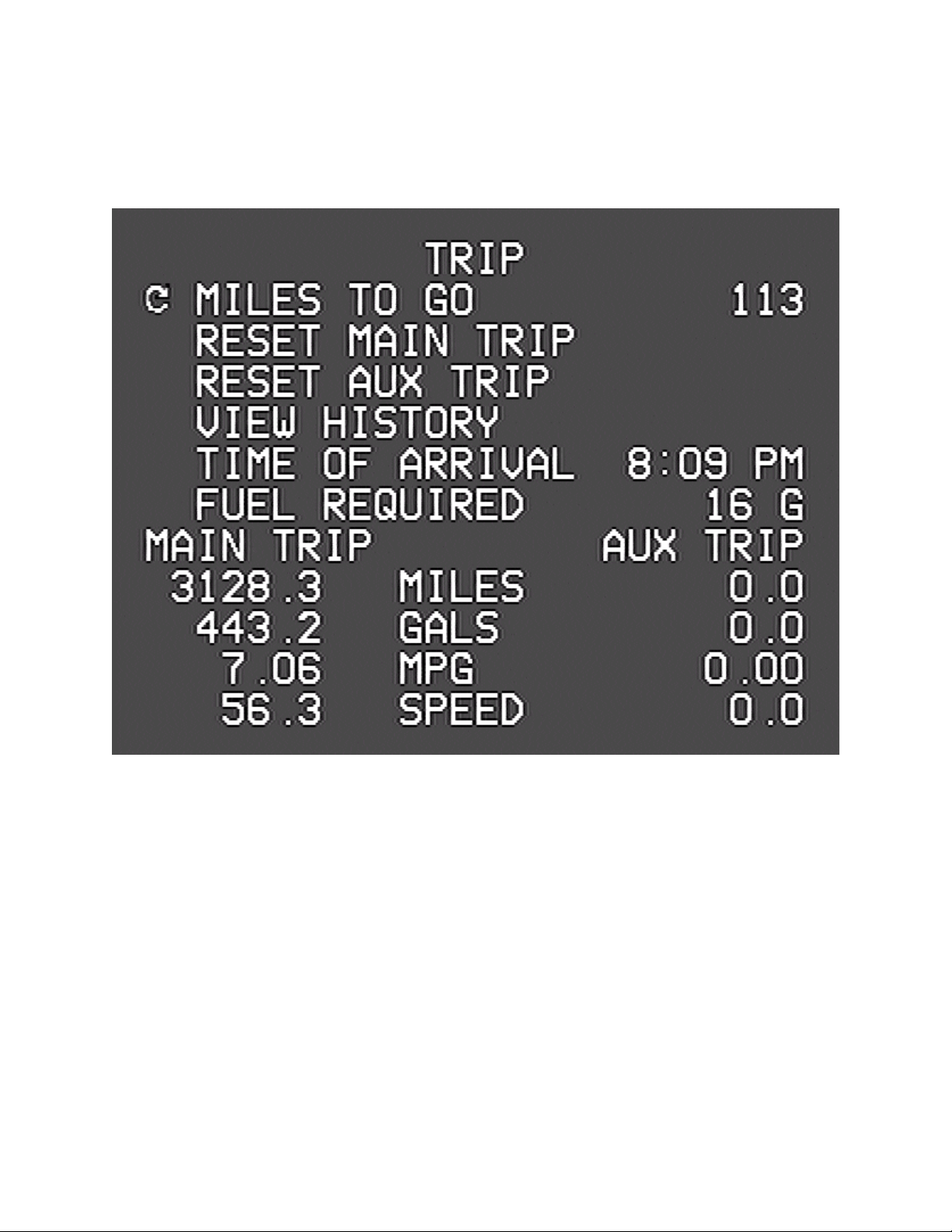
Trip Screen
The first “Detail” screen displays information on the current trip. The
unit tracks two trips simultaneously. One might use the main trip to
track mileage and fuel, say, each time leaving home, while the “auxiliary”
trip keeps a cumulative total for the season or year. Optionally, it can e
reset at each refueling.
10

Miles to Go
Use the kno to set this value. While driving, the VMS 350 will count
down the miles, and provide a continuing estimate of the
Time of Arrival
and the amount of
Fuel Required.
These estimates will e ased on the
speed and fuel consumption averages for the Main Trip.
By entering-in the destination distance, from a GPS or map for example,
a good estimate of the arrival time and fuel required can e known. This
can help plan and manage stops. The Arrival Time can also e watched
while adjusting the Miles to get the est travel distance on the next leg.
Clearing the Trips
By pressing the kno while the cursor points to the Reset Main Trip or
Reset Aux Trip items, either of the two trip odometers can e zeroed
out. Once cleared, however, the action cannot e undone.
Trip History
When the Main Trip odometer is 'cleared,' the data are recorded in the
Trip History. The unit can store up to 64 trips in its history. To view
the history, select the View History item. Then, use the kno to scroll
through all the trip data.
Trips of less than five miles are not recorded in the history. To clear the
history, see the Configuration Screen descri ed elow.
Trou leshooting
Fault Detection
In the event of a detected fault within the house systems, a fault
indication may appear. As not all coaches are using these and other
specific features, your mileage may vary. Call us for any questions
regarding these or other questions.
11

Limited Warranty
The o ligation of SilverLeaf Electronics under this warranty shall e
limited to repair or replacement (at our option) during the warranty
period of any part which proves defective in material or workmanship
under normal installation, use, and service, provided the product is
returned to SilverLeaf Electronics. The warranty period shall e one year
from date of purchase of the VMS 350™, or purchase of the finished
coach with the VMS 350™ installed.
This warranty shall e invalid if the product is damaged as a result of
defacement, misuse, a use, neglect, accident, destruction, alteration,
improper electrical voltages or currents, repair or maintenance y any
party other than SilverLeaf Electronics or an authorized service facility,
or any use violative of instructions furnished y us.
This one-year warranty is in lieu of all other expressed warranties,
o ligations, or lia ilities. Any implied warranties, o ligations, or lia ilities,
including ut not limited to the implied warranties of merchanta ility and
fitness for a particular purpose, shall e limited in duration to the one-
year duration of this written limited warranty.
In no event shall SilverLeaf Electronics e lia le for any special, incidental,
or consequential damages for reach of this or any other warranty,
expressed or implied, whatsoever.
This warranty gives you specific legal rights, and you may also have other
rights which vary from state to state.
12
SilverLeaf Electronics, Inc.
2490 SW Ferry St.
Al any, OR 97322
Worldwide: (541) 967-8111
Toll Free in US: (888) 741-0259
w w w . s i l v e r l e a f e l e c t r o n i c s . c o m
Table of contents
Popular Motorhome manuals by other brands

Country Coach
Country Coach DynoMax Inspire 360 2008 owner's guide

Fleetwood
Fleetwood American Dream WIDE BODY 1998 owner's manual

Carriage
Carriage Carri-Lite 2001 owner's manual

Sunrise
Sunrise Takapu 736G Get to know
Fleetwood
Fleetwood Tioga Arrow 1984 manual

Triple E
Triple E 1991 Empress Class A owner's manual


