Simba X-Press Installation and operation manual

X-PRESS
OPERATORS MANUAL
& PARTS LIST
ENGLISH
P17897B
19/07/11

ENG If you require a copy of this document in your native language
pleasecontactyourdealerorSimbaInternationalLtd.(P17897)
CZE Požadujete-li kopii tohoto dokumentu ve svém rodném jazyce,
obraťte se prosím na svého prodejce nebo na společnost Simba
InternationalLtd.(P17962)
HUN Haszeretnéeztaleírástmagyarulismegkapni,kérjük,értesítsea
forgalmazójátvagyaSimbaInternationalLtd.-t.(P17963)
FRA Pourobtenirunexemplaireduprésent document dans la langue
de votre choix, veuillez contacter votre représentant ou Simba
InternationalLtd.(P17964)
LIT JeiprireiktųšiodokumentokopijosJūsųgimtąjakalba,kreipkitėsį
savoplatintojąarbaį„SimbaInternationalLtd“.(P17965)
BUL Ако ви е необходимо копие на този документ на родния ви
език, моля да се обърнете към вашия дилър или към Simba
InternationalLtd.(P17966)
RUM Dacă aveţi nevoie de o copie a acestui document în limba
dumneavoastră natală vă rugăm să vă contactaţi dealerul sau
SimbaInternationalLtd.(P17967)
RUS Чтобы получить копию данного документа на вашем родном
языке, обратитесь к своему дилеру или в компанию «Simba
InternationalLtd.»(P17968)
GER WennSieeinExemplardiesesDokumentsinIhrerMuttersprache
brauchen,dannwendenSiesichbitteanIhrenHändleroderandie
SimbaInternationalLtd.(P17969)

3X-Press
Operating Instructions
DeclarationofConformity
DECLARATION OF CONFORMITY
Simba International Limited hereby declare that the Simba X-Press, as dened by the Serial Number
attachedtotheMachineChassis,conformswiththefollowingDirectivesandRegulations,andhasbeen
certiedaccordingly.
EC Machinery Directive 2006/42/EC.
The Supply of Machinery (Safety) Regulations 2008.
The Provision and Use of Work Equipment Regulations 1998.
Specicallyrelatedharmonisedstandardsare:
EN ISO 12100-1: 2003 (Safety of Machinery).
EN ISO 12100-2: 2003 (Safety of Machinery).
EN ISO 4254-1: 2009 (Agricultural machinery - Safety - General Requirements).
THEMANUFACTURER:
SimbaInternationalLimited
WoodbridgeRoad
SLEAFORD
Lincolnshire
NG347EW
England
Telephone(+44)(0)1529304654.
CERTIFIEDONBEHALFOFSIMBAINTERNATIONALLIMITED:
ColinAdams
ManagingDirector

X-Press
Operating Instructions
4
WARRANTY
TERMS AND CONDITIONS
InthiswarrantySimbaInternationalLtd.,isreferredtoas“theCompany”.
1. SubjecttotheprovisionsofthiswarrantytheCompanywarrantseachnewmachinesoldbyitto
besoldfreefromanydefectinmaterialorworkmanshipforaperiodof12monthsfromdateof
installationwiththeend-user.
Somespecicitemshaveadditionalwarrantyoverandabovethestandard12months.Detailsof
thesecanbeobtaineduponrequestdirectlyfromthedistributororSimbaInternationalLtd.
2. IfthemachineorpartthereofsuppliedbytheCompanyisnotinaccordancewiththewarranty
giveninclause1theCompanywillatitsoption:
(a) makegoodthemachineorpartthereofattheCompany’sexpense,or
(b) makeanallowancetothepurchaseragainstthepurchasepriceofthemachineorpart
thereof,or
(c) acceptthereturnofthemachineandatthebuyersoptioneither:
I) repayorallowthebuyertheinvoicepriceofthemachineorpartthereof,or
II) replacethemachineorpartthereofasisreasonablypractical.
3. ThiswarrantyshallnotobligetheCompanytomakeanypaymentinrespectoflossofprotor
otherconsequentiallossorcontingentliabilityofthePurchaserallegedtoarisefromanydefect
inthemachineorimposeanyliabilityontheCompanyotherthanthatcontainedinclause2.
4. AnyclaimunderthiswarrantymustbenotiedtotheCompanyinwritingspecifyingthematters
complainedofwithin14daysfromthedateofrepair.
5. Anyclaimunderthiswarrantymustbemadebytheoriginalpurchaserofthemachineandisnot
assignabletoanythirdparty.
6. Ifthepurchaserhiresoutthemachinetoanythirdpartythewarrantyshallapplyonlytomatters
notiedtotheCompanyinwritingwithin90daysofthedateofdeliveryandclause1shallberead
asiftheperiodof90daysweresubstitutedfortheperiodof12months.
7. Thewarrantywillceasetoapplyif:
(a) anypartsnotmade,suppliedorapprovedinwritingbytheCompanyarettedtothemachineor
(b) anyrepairiscarriedouttothemachineotherthanbyorwiththeexpresswrittenapprovalofthe
Companyor
(c) anyalterationsnotexpresslyauthorizedbytheCompanyinwritingaremadetothemachineor
(d) themachineisdamagedbyaccidentor
(e) themachineisabusedoroverloadedorusedforapurposeorloadbeyonditsdesigncapabilities,
orusedinconjunctionwithatractorwhosepoweroutputcapabilityexceedsthestatedimplement
powerrequirementbymorethan40%.Forthepurposeofthesetermsandconditions,“stated
implementpowerrequirement”referstowheeledtractorsunlessspecicallystated.Thesepower
requirementsshouldbereducedby20%whenusedinconjunctionwithtrackedtractors.
(f) themachineisoperatedaspartofa‘cultivationtrain’wheremorethanoneimplementisbeing
towed,withouttheexpresswrittenapprovalofSimbaInternationalLtd.
(g) anymaintenanceisnotcarriedoutinaccordancewiththeserviceschedulesintheoperator’s
manual.
(h) theInstallationandWarrantyRegistrationCerticateisnotreceivedbySimbaInternationalLtd.,
ServiceDept.,WoodbridgeRoad,Sleaford,Lincolnshire,England,NG347EW,within7daysof
installinganewmachine.
Warranty

5X-Press
Operating Instructions
Machine Identication
Entertherelevantdatainthefollowinglistuponacceptanceofthemachine:
OperatingInstructions/SparePartsList:July2011
Dealer Address: Name: ________________________________________
Street: ________________________________________
Place: ________________________________________
Tel.: ________________________________________
Dealer’sCustomerNo.: ______________________________
SIMBA Address: SIMBA
WoodbridgeRoadInd.Est.
Sleaford
Lincolnshire
NG347EW
Tel.: +44(0)1529304654
Fax: +44(0)1529413468
SIMBACustomerNo.: ______________________________
Serial Number
Type of Machine
Machine Width
Year of Construction
Delivery Date
First Operation
Accessories
MachineIdentication

X-Press
Operating Instructions
6
Contents
Contents
MachineIdentication.............................................................................................................5
Introduction ..............................................................................................8
Foreword..........................................................................................................................8
WarrantyGuidelines.........................................................................................................8
1. Safety Data .......................................................................................9
1.1 SafetySymbols......................................................................................................9
1.2 UsefortheIntendedPurpose............................................................................. 11
1.3 OperationalSafety................................................................................................ 11
1.4 NoLiabilityforConsequentialDamage................................................................ 11
1.5 RoadTrafcSafety...............................................................................................12
1.6 AccidentPrevention.............................................................................................12
1.6.1HitchingUptheMachine......................................................................................12
1.6.2OntheHydraulicSystem......................................................................................12
1.6.3ChangingEquipment............................................................................................13
1.6.4DuringOperation..................................................................................................13
1.7 Servicing&Maintenance......................................................................................13
1.8 OperatingAreas...................................................................................................14
1.9 AuthorisedOperators...........................................................................................14
1.10 ProtectiveEquipment...........................................................................................14
2. Transportation and Installation .....................................................15
2.1 Delivery................................................................................................................15
2.2 Transportation......................................................................................................15
2.3 Installation............................................................................................................15
2.4 HitchingUp...........................................................................................................16
2.4.1HitchingupaTractortotheX-Press/PreparingforTransport............................16
2.5 FoldingandUnfolding..........................................................................................17
2.5.1UnfoldingintotheWorkPosition..........................................................................17
2.5.2FoldingintotheTransportPosition.......................................................................17
2.6 AirBrakeCouplingProcedure..............................................................................18
2.6.1WhenCoupling....................................................................................................18
2.6.2WhenDe-coupling................................................................................................18
2.7 Preceding&TrailingImplements.........................................................................19
2.7.1HitchingaDiscHarrowtotheX-Press.................................................................19
2.7.2TransportinganX-PressTowedBehindaDiscHarrow......................................20
2.7.3ChangingfromWorktoRoadTransport(X-PressBehindaDiscHarrow)...........20
2.7.4HitchingaRearRolltotheX-Press.....................................................................20
2.8 WhenDrivingontheRoad...................................................................................21
2.9 ParkingtheMachine.............................................................................................21
3. Technical Data X-Press ..................................................................23

7X-Press
Operating Instructions
Contents
4. Adjustment/Operation ....................................................................24
4.1 Description...........................................................................................................24
4.2 DiscUnits.............................................................................................................26
4.3 DoubleDiscRoller................................................................................................27
4.4 DDlightRoll.........................................................................................................33
4.5 WorkSettings.......................................................................................................28
4.6 UsingShims.........................................................................................................29
4.7 StartingSettings...................................................................................................29
4.7.1VariationofSettings.............................................................................................30
4.8 AdjustingDiscFrameDepth.................................................................................31
4.9 WorkInstructions..................................................................................................31
4.10 Checks.................................................................................................................31
5. Servicing and Maintenance ...........................................................32
5.1 Servicing...............................................................................................................32
5.2 Cleaning...............................................................................................................32
5.3 DiscHubMaintenance........................................................................................32
5.3.1TighteningDiscHubs...........................................................................................32
5.3.2BearingSeals.......................................................................................................33
5.4 Brakes&WheelHubs..........................................................................................33
5.5 DoubleDiscAxles................................................................................................33
5.6 DDLightRoll........................................................................................................33
5.7 ToAdjusttheSystemPressure............................................................................34
5.8 PreparationforStorage........................................................................................35
5.9 OperatorSupport..................................................................................................35
5.10 MaintenanceIntervals..........................................................................................35
5.11 MaintenanceOverview.........................................................................................36
5.12 LubricatingtheMachine.......................................................................................37
5.13 HandlingofLubricants..........................................................................................37
5.14 Lubricants&HydraulicOil...................................................................................38
6. Faults and Remedies ......................................................................39
7. Parts & Assembly ...........................................................................41

X-Press
Operating Instructions
8
Introduction
Foreword
Make sure you have read and follow the
OperatingInstructionscarefullybeforeusing
the machine. By doing so, you will avoid
accidents,reducerepaircostsanddowntime
andincreasethereliabilityandservicelife
ofyourmachine.Payattentiontothesafety
instructions!
SIMBA will not accept any responsibility
for any damage or malfunctions resulting
from failure to comply with the Operating
Instructions.
These Operating Instructions will assist
youingettingtoknowyourmachineandin
usingitcorrectlyforitsintendedpurposes.
First,youaregivengeneralinstructionsin
handlingthemachine.Thisisfollowedby
sections on servicing, maintenance and
theactiontobetakenshouldamalfunction
occur.
Theseoperatinginstructionsaretoberead
andfollowedbyallpersonsworkingonor
withthemachine,e.g.:
• Operation (including preparation,
remedying of faults in the operating
sequenceandservicing).
• Maintenance (maintenance and
inspection)
• Transportation.
Together with the Operating Instructions,
you receive a Spare Parts List and a
Machine Registration form. Field service
technicianswillinstructyouintheoperation
and servicing of your machine. Following
this, the Machine Registration form is to
be returned to your dealer. This conrms
your formal acceptance of the machine.
Thewarrantyperiodbeginsonthedateof
delivery.
We reserve the right to alter
illustrations as well as technical
dataandweightscontainedinthese
OperatingInstructionsforthepurpose
ofimprovingthemachine.
Warranty Guidelines
Theperiodofliabilityformaterialdefects
(warranty) relating to our products is 12
months. Inthecaseofwrittendeviationsfrom
thestatutoryprovisions,theseagreements
shallapply.
Theyshallbecomeeffectiveuponinstallation
ofthemachinewiththeendcustomer.All
wearpartsareexcludedfromthewarranty.
All warranty claims must be submitted to
SIMBAviayourdealer.
Introduction
9X-Press
Operating Instructions
1. Safety Data
Thefollowingwarningsandsafetyinstruc-
tionsapplytoallsectionsoftheseOperating
Instructions.
1.1 Safety Symbols
On the machine
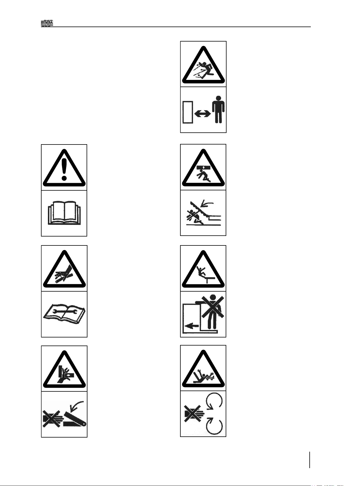
Nopassengersareallowed
onthemachine!
Keep clear of the working
rangeoffoldablemachine
components!
Never reach into areas
wherethereisadangerof
being crushed by moving
parts!
Watch out for escaping
pressurised uids! Follow
the instructions in the
OperatingInstructions!
Read and observe the
Operating Instructions
before starting up the
machine!
Never reach into any
revolvingparts!
Parts may fly off during
operation. Keep a safe
distance away from the
machine!
1.SafetyData
X-Press
Operating Instructions
10
1.SafetyData
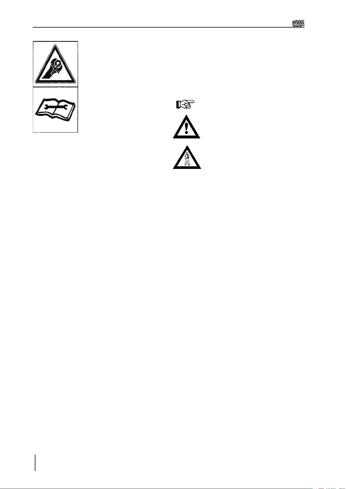
Refer to Operating
Instructions before
attemptingmaintenance.
Operating Instructions:
The Operating Instructions distinguish
betweenthreedifferenttypesofwarningand
safety instructions.The following graphic
symbolsareused:
Important!
Riskofinjury!
Riskoffatalandseriousinjuries!
Itisimportantthatallthesafetyinstructions
contained in these Operating Instructions
andall the warning signsonthe machine
arereadcarefully.
Ensurethatthewarningsignsarelegible.
Replace any signs that are missing or
damaged.
Theseinstructionsmustbefollowedinorder
topreventaccidents.Informotherusersof
thewarningsandsafetyinstructions.
Donotcarryoutanyoperationswhichmay
affectsafeuseofthemachine.
Allreferencestoleftandrightinthismanual
aremadefromtherearofthemachine,facing
the direction of travel (unless otherwise
stated).

11X-Press
Operating Instructions
1.SafetyData
1.3 Operational Safety
The machine is to be put in operation
only after instruction has been provided
by an employee of the authorised dealer
or an employee of SIMBA.The “Machine
Registration”formistobe completedand
returnedtoyourdealer.
All protective and safety equipment, such
as removable protective equipment, must
beinplaceandfunctioningreliablybefore
themachineisputinuse.
Checkscrewsandboltsregularly
for tightness and retighten if
necessary.
In the event of malfunctions,
stop and secure the machine
immediately.
Ensurethatanyfaultsareremedied
immediately.
1.4 No Liability for
Consequential Damage
The X-Press has been manufactured by
SIMBAwithgreatcare.However,problems
may still occur when it is used for the
intendedpurpose.Thesemayinclude:
•Wornwearingparts.
•Damagecausedbyexternalfactors.
•Incorrectdrivingspeeds.
• Incorrect setting of the unit (incorrect
attachment, non-adherence to the Setting
instructions).
Therefore, it is crucial to always
check your machine before and
during operation for correct
operationandadequateapplication
accuracy.
Compensationclaimsfordamagewhichhas
not occurred to the machine is excluded.
This includes any consequential damage
resultingfromincorrectoperation.
1.2 Use for the Intended
Purpose
The SIMBA X-Press is built using the
latest technology and in accordance with
therelevantrecognisedsafetyregulations.
However,risksofinjuryfortheoperatoror
thirdpartiesandimpairmentofthemachine
orothertangibleassetscanariseduringuse.
Themachineisonlytobeoperatedwhen
inatechnicallyperfectconditionandforthe
intendedpurpose,takingintoconsideration
safetyandrisksandfollowingtheOperating
Instructions. In particular, faults that can
impairsafetyaretoberemediedimmediately.
OriginalpartsandaccessoriesfromSIMBA
have been specially designed for this
machine.Sparepartsandaccessoriesnot
supplied by us have not been tested or
authorised.Installationoruseofnon-original
SIMBA products may have a detrimental
effect on specic design features of the
machineandaffectthesafetyof machine
operatorsandthemachineitself.SIMBAwill
acceptnoliabilityfordamageresultingfrom
theuseofnon-originalpartsoraccessories.
TheSIMBAX-Pressisdesignedsolelyas
acultivationimplement.Useforanyother
purpose,e.g.,asameansoftransport,will
bedeemedtobeimproperuse.SIMBAwill
acceptnoliabilityfordamageresultingfrom
improperuse.Theriskwillbebornesolely
bytheoperator.
Use of the X-Press behind high power
tractors (in excess of 40% above the
maximumrecommended)canleadtohigh
loads and stresses which can cause long
termstructuraldamagetothechassisand
key components. Such overloading can
compromisesafetyandistobeavoided.
X-Press
Operating Instructions
12
1.5 Road Trafc Safety
When driving on public roads, tracks and
areas,itisimportanttoobservetherelevant
road traffic laws as well as the specific
regulationsrelatingtothismachine.
Payattentiontothepermittedaxle
loads, tyre carrying capacity, and
total weight in order to maintain
adequatebrakingandsteerability
(these gures are shown on the
serialplate).
Passengers on the machine are
strictlyforbidden!
Max.roadtransportspeed16mph
(25km/h).
1.6 Accident Prevention
InadditiontotheOperatingInstructions,itis
importanttoobservetheaccidentprevention
regulations specied by agricultural trade
associations.ItistheOperator’sresponsibility
toensurethatallotherpersonsareexcluded
fromthedangerzonessurroundingoronthe
machineduringitsoperation.
ItistheOwner’sresponsibilitytoensure:
•theOperatoristrainedandcompetentto
usethemachine
&
tractor,
•thetractorissuitableforthemachine
•adequateRiskandCOSHHassessments
have been undertaken regarding the
machine’s use. Specically, these include
issues concerning contact with the soil,
dust, crop residues, chemicals, lubricants
andother compounds duringoperationor
maintenance,andthepossibilityofstones
beingejectedathighspeedduringwork.
1.6.1 Hitching-up the
machine
There is a risk of injury when hitching/
unhitching the machine. Observe the
following:
•Securethemachineagainstrolling.
• Take special care when reversing the
tractor!
•Thereisariskofbeingcrushedbetween
themachineandthetractor!
•Parkthemachineonrm,levelground.
1.6.2 On the Hydraulic
System
Do not connect the hydraulic lines to the
tractoruntilbothhydraulicsystems(machine
andtractor)aredepressurised.
Anyhydraulicsystemcontaining
an accumulator can remain
under pressure permanently
(even after following manual
depressurisation procedures
with a tractor / implement
combination). It is therefore
importanttocheckalllines,pipes,
andscrewconnectionsregularly
for leaks and any recognisable
externaldamage.
The hydraulic circuit contains
specialisedttingswhichshould
notbetamperedwithunderany
circumstances. Do not attempt
tomodify hoseroutings orhose
clampingarrangements,doingso
mycauseseriousdamagetothe
machineand/orinjury.
1.SafetyData
Bewareoftrappinghazardswhen
manipulating the parking stands
or other moving parts. Ensure
anyheavy componentsare fully
supportedwhenremovingpins/
bolts.

13X-Press
Operating Instructions
Only use appropriate aids when checking
forleaks.Repairanydamageimmediately.
Spurtingoilcancauseinjuriesandres!
Incaseofinjury,contactadoctorimmediately.
The socket and plugs for the hydraulic
connections between the tractor and the
machine should be colour-coded in order
toavoidincorrectuse.
1.6.3 Changing Equipment
• Secure the machine to prevent it from
accidentallyrollingaway!
• Use suitable supports to secure any
raisedframesectionssuspendedabove
you!
• Caution!Riskofinjuryduetoprojecting
parts!
Never climb on to rotating parts
suchastherollunit.Theseparts
mayrotatecausingyoutoslipand
sufferseriousinjury!
Removing components during
maintenance may affect the
stability of the machine. Ensure
it is fully supported in case of
unexpectedweightshifts.
1.6.4 During Operation
Ensurethattheworkingrangeandthearea
around the machine are clear (children!)
beforeoperatingthemachine.
Alwaysensureadequatevisibility!
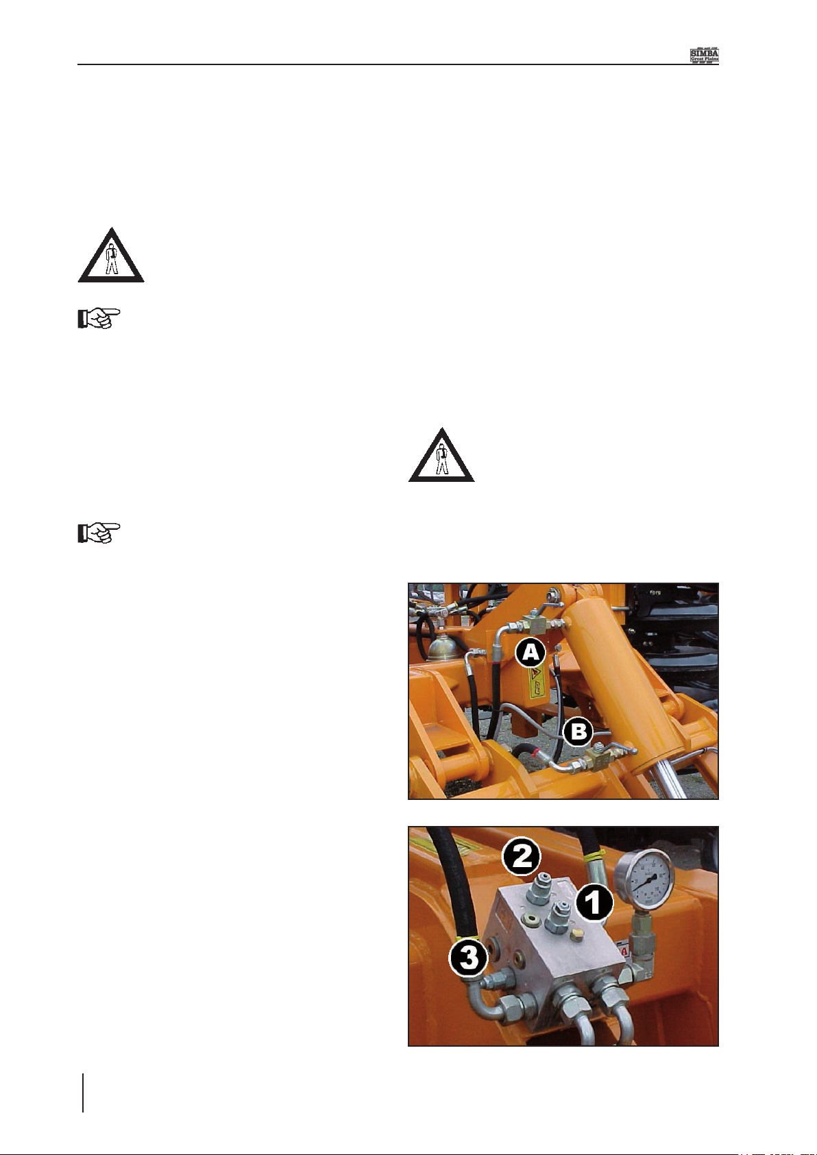
Fig. 1.01: HydraulicTaps
Donotstandonthemachinewhileitisin
operation!
Operatorsmusthaveavaliddrivinglicence
in order to drive on public roads. In the
operatingarea,theoperatorisresponsible
forthirdparties.
Thepersoninchargemust:
•provide the operatorwitha copyof the
OperatingInstructions,and
• ensure that the operator has read and
understoodtheinstructions.
•makesurethattheoperatorisawareofthe
specicregulationsrelatingtothemachine
whendrivingonpublicroads.
1.7 Servicing &
Maintenance
Ensurethatregularchecksandinspections
are always carried out within the periods
required by law or specified in these
OperatingInstructions.
Whencarryingoutserviceandmaintenance
workalways:
• switchoffthetractorengineandremove
theignitionkey.
• wait until all the machine parts have
stoppedmoving.
• depressurisethehydraulicsystem.
Many hydraulic circuits contain lock or
overcentrevalveswhichcanretainpressure
in the lines even after depressurising the
tractor side of these circuits. If in doubt,
consult trained personnel (such as your
localSimbaDealer)toensuresuchvalves
aredepressurisedtothecorrectprocedure
before removing or servicing any parts
connecteddownstreamofthesevalves.
1.SafetyData

X-Press
Operating Instructions
14
1.8 Operating Areas
The operating areas include the drawbar,
hydraulicconnectionsanddepthadjustment
equipmentaswellasalloperatingpoints
requiringmaintenance.
All operating areas will be specied and
describedindetailinthefollowingchapters
onservicingandmaintenance.
Observe all safety regulations included in
thesectiondealingwithSafety,andinthe
subsequentsections.
1.9 Authorised Operators
Only those persons who have been
authorised and instructed by the operator
may operate the machine. The operator
mustbeatleast16yearsofage.
1.10 Protective
Equipment
Foroperationandmaintenance,yourequire:
•Tightttingclothing.
• Strong protective gloves (to provide
protection against sharp-edged machine
components).
•Protectivegoggles(tostopdirtgettinginto
youreyes).
Check all hydraulic lines for leaks, loose
connections, chafe marks and damage.
Remedyanydecienciesimmediately!Pay
particularattentiontohoserenewalintervals
as outlined in the specic sections which
follow.ALL hydraulic hoses have a safe
maximumworkinglifeof6(SIX)yearsfrom
dateofinstallation,providedtheyremainina
safecondition.Hoseswhichexceed6years
ofageshouldbereplaced,orinspectedand
certied by a suitably qualied person to
haveanextendedlifeperiodwhichshould
berecorded.
Payparticularattentiontothoseitemswhich
require specialist service tools or training
tobecarriedoutbyqualiedpersonnel.Do
notattempttoservicetheseitemsyourself!
Theseincludeitemsretainingpressure(e.g.
accumulatorcircuits),orforce(e.g.spring
tines),andDDRollsofanytype.
Prior to performing maintenance and ser-
vicingwork,ensurethatthemachineisposi-
tionedonsolid,levelgroundandissecured
topreventit rolling away.Donotuseany
partstoclimbontothemachineunlessthey
arespecicallydesignedforthispurpose.
Before cleaning the machine with water,
steam jets (high-pressure cleaning appa-
ratus) or other cleaning agents, cover all
openingsintowhich,forreasonsofsafety
or operation, no water, steam or cleaning
agents are to penetrate (bearings, for in-
stance).
Lubricateallthelubricatingpointstoforce
outanytrappedwater.
When carrying out servicing and main-
tenance work, retighten any loose screw
connections.
Whenservicingthemachinetakeprecauti-
onsagainstsoil,dust,seedcoatings,oilor
any other hazardous substances that you
mightencounter.
1.SafetyData
On a new machine tighten all nuts and
boltsafter5hoursworkandagainafter15
hours.Thisalsoappliestopartsthathave
beenmovedorreplaced.Aftertheinitial15
hoursofworkaonceaweekcheckshould
besufcientdependingondailyworkrates.

15X-Press
Operating Instructions
2.3 Installation
Whencarryingoutinstallationandmainte-
nanceworkthereisahigherriskofinjury.
Itisimportantthatyoufamiliariseyourself
with the machine and read the Operating
Instructionsbeforehand.
Operatorinstructionandinitialinstallationof
themachinearecarriedoutbyourservice
techniciansorauthoriseddistributors.
Themachinemustnotbeusedinanyway
beforehand!The machinecan onlybere-
leasedforoperationafterinstructionshave
beenprovidedbyourservicetechniciansor
authoriseddistributors.
•Ifanymodulesorpartshavebeenremoved
fortransportation,theseshallbemountedby
ourservicetechnicians/authoriseddealers
beforetheinstructiontakesplace.
•Checkallimportantscrewconnections!
•Lubricateallnipplesandjoints!
•Checkallhydraulicconnectionsandlines
fordamage.
2. Transportation and
Installation
Transportationandinitialinstallationofthe
machinearedescribedinthischapter.
2.1 Delivery
The machine is normally delivered, fully
assembled.
•Themachinecanbeliftedoffwithacrane
orothersuitableliftingequipment.
•Themachineshouldbehitchedtoatractor
anddrivenoffalow-loader.
2.2 Transportation
TheX-Presscanbetransportedonpublic
roadsbyhitchingituptoatractororona
low-loader.
• It is important to observe the permitted
dimensionsandweightswhentransporting
themachine.
•Ifthemachineistransportedonatraileror
alow-loader,itmustbesecuredusingstraps
orotherdevices.
• Before transporting the machine on
public roads, it must be adjusted to its
transportationpositionandthestipulations
relatingtoroadtransportationfullled.
The transportation width can
varyaccordingtotheadjustment
of working parts (eg. discs, roll,
etc). It may be necessary to
adjusttheseelementsinorderto
achieve the minimum transport
width.
Adjustments, including the
attachmentoftransportdevices,
shouldbemadeatgroundlevel;
lowering the machine may be
necessarytoachievethis.
• The maximum permissible speed is 25
km/h.
2.Transportation/Installation
X-Press
Operating Instructions
16
2.4 Hitching Up
2.4.1 Hitching up a Tractor
to the X-Press / Preparing for
Transport
When hitching-up the machine,
ensurethatno-oneisbetweenthe
tractorandthemachine.
When the X-Press is parked for
extendedperiodsoftimeitshould
ideally be left in the unfolded,
i.e. work, position for stability,
safety and ease of access for
maintenance. However, parking
theX-Pressinthefoldedposition
(usingtheparkingstandsprovided)
isacceptableinthenormalcourse
ofoperation.
Tractor Oil Flow Adjustment:
Asageneralrulethetractoroilow
rateshouldbesetinthelowestset-
tingbeforestarting.Thiscanthen
beincreasedtoallowthedesired
rate of operation as applicable.
Thiswillminimiseexcessiveoilow
andconsequentpowerusageand
heatgeneration.
1. Ensure the tractor hydraulics are
depressurised and in the locked or
closed(notoat)setting.
2. Ensuretherearaxletapsarelocked
to avoid high pressure at the quick
releasecouplings.
3. Couple the hydraulic hoses to the
tractor ensuring that the two wing
hoses (yellow) are together and the
twodrawbarcylinderhoses(red)are
together.
4. Connect the tractor to the drawbar
usingthehydraulicstoraiseorlower
theheightoftheshackle.
5. Opentherearaxletaps
6. Carefully operate the hydraulics to
lowerthedrawbarandtilttheX-Press
ontotheroadtransportwheels.Fully
extendthedrawbarandaxlecylinders.
7. Ifthemachineisunfoldedthenoperate
thefoldcircuitandfoldthemachine.
Fitthewingstraptotiethetwowing
sectionstogether.
Themachineshouldbelowered
so that the transport strap can
bettedfromtheground.Donot
climbonthemachine.
8. Ensurethatparkingstandsarelocked
upintheirworkpositions.
Fig. 2.01: Rear Axle Cylinder
Fig. 2.02: Manifold Block
2.Transportation/Installation

17X-Press
Operating Instructions
2.5 Folding and Unfolding
2.5.1 Unfolding into the Work
Position
1. Ensurethatthetapsontherearaxle
cylinder(Fig.2.01,tapsAandB)arein
theopenposition(ie.inlinewithow).
2. Removethetransportstrapfromthe
rearwingcylinders.Donotclimbon
themachinetoremovethetransport
strap.
3. Lift the machine clear of the ground
readyforunfolding.
4. Operatethehydraulicstofullyunfold
thewings.
When wings are fully lowered
they will appear to be lower at
the wingtips. This is to enable
themachineto‘oat’overuneven
groundinworkandisnormal.
5. Ensurethattheparkingstandsarein
thefullyraisedposition.
6. Lowerthemachinetothegrounduntil
thedrawbarcylinderstouchthedepth
stops.
7. Retract the rear axle cylinders
completely.
8. Closethetapsontherearaxletolock
thewheelsclearofthegroundduring
work.
9. Check the wing pressure on the
gauge(showninFig.2.02).Ifthisis
aboveorbelowthedesiredvaluethen
pressurisethewingstofoldwhichwill
zerothesetting.Increasethepressure
onthe cylindersidebyadjustingthe
valve (Fig.2.02, valve 3) clockwise.
Byrotatinganticlockwisethepressure
willbereduced(seepage34formore
details).Pressurisetounfolduntilthe
requiredpressureisachieved.
10. Draw the X-Press into work then
set the desired pitch of the machine
by adding or removing shims from
the drawbar cylinder or disc frame
adjusters.Thechassisshouldideally
besettorunslightlynosehigh.The
drawbarhydraulicsmaybeworkedin
oatifdesired.
2.5.2 Folding into the
Transport Position
1. Opentheaxletaps(Fig.2.01,tapsA
andB).
2. Operatethehydraulicstofullyraisethe
machine.
3. Foldthemachinefully.
4. Lower the machine to maximise
stability while ensuring adequate
clearanceforroadtransport.
5. Close the taps on the rear axle. Fit
thetransportstrapfortransportsafety.
The strap should be tted from the
ground.Donotclimbonthemachine.
6. Themachineisreadyfortransport.If
the X-Press is to be unhitched from
the tractor in the folded position the
parkingstandsshouldbelowered.
Fig. 2.03 Folded Machine
2.Transportation/Installation

X-Press
Operating Instructions
18
2.5.3 Following Harrow
Operation
Into Work:
1. Arrive in field and unfold machine
accordingtooperatinginstructions
2. Whilstatrearofmachineclosingaxle
tapsmovePins(qty2)fromfrontmost
holes(bylug)torearhole.
3. Removepinonouterquadrantplate
andre-positioninthehighestpossible
holeforstorage.
4. Drivingforwardwilliptheharrowout
intoaworkposition
5. Whenturninginwork,tipthemachine
rearwards into the roll. Reversing
the machine in this position allows
theharrowtoiptemporarilyintothe
transport position. Driving forwards
againipstheharrowbackintowork.
Turninginworkmustonlybeon
theDD700rearroll.Attemptingto
lowerthetransportaxlewiththe
harrow in the work position will
seriously damage the following
harrowcomponents.
Into Transport:
1. TilttheX-Pressontotherearrolland
reverse the machine slightly as if
performingaheadlandturn.
2. Whilst at the rear of the machine
openingthetransportaxletaps,move
theharrowclamppins(qty2)fromthe
frontholestotherearholesbythelugs.
3. Usethepinintheouterquadrantplate
tothelowestpositionpermittedthatit
willlocktheharrowarmdown.
4. Continue folding the X-Press in
accordance with the operating
instructions.
2.6 Air Brake Coupling
Procedure
Pleaserefertothefollowingprocedurewhen
couplingordecouplinganyitemofSIMBA
machineryttedwithanAIRbrakeorAIR
and HYDRAULIC brake system. Please
notethatthisproceduredoesnotapplyto
any machines tted with a HYDRAULIC
systemONLY.
2.6.1 When Coupling
1. Reverse up to the machine and
connectthemachinetothetractoras
instructedtoinSection2.4.1.
2. With the machine connected couple
theairlines.Whencouplingensurethe
yellowlineisattachedrstfollowedby
theredline.
3. Your brake hoses are now attached
andarereadyforoperation.
4. Continuewiththecouplingprocessas
instructedinSection2.4.1.
2.6.2 When De-coupling
1. Bring the machine to the parking
positionasinstructedtoinSection2.9.
2. With the machine still connected to
thetractorremovetheredbrakeline
followedbytheyellowline.
2.Transportation/Installation

19X-Press
Operating Instructions
2.7 Preceding & Trailing
Implements
2.7.1 Hitching a Disc Harrow
to the X-Press
1. Removethetransportstrapsfromthe
disc harrow, exercise great CARE
whenextendingtheaxlecylinder.
2. Reverse the disc harrow up to the
X-Pressdrawbarensuringthatthetwo
drawbarsarealignedallowingaslight
clearancetoenablethemachinesto
becoupledtogether.
3. Lowerthedischarrowtotheground.
4. Connect the four hydraulic hoses
fromtheX-Pressintothedischarrow
rear outlets ensuring that the two
winghosesaretogetherandthetwo
drawbarcylinderhosesaretogether.
Ensurethatthefoldingcircuitsandlift
drawbarcircuitsarecoupledcorrectly.
3. YourbrakeswillnowbeONandwill
hold,ensuringtheyhavebeenadjusted
andmaintainedcorrectly,themachine
inposition.(note:ifthemachine‘stank
is drained of air once all lines have
beendetachedthebrakeswillcomeoff
(samesituationaspushingtheshunt
valve).
4. Continuede-couplingthemachineuntil
itisfullydisconnected.
Byfollowingtheaboveinstructions
you will see that at NO point
in the coupling or decoupling
process has the red line been
left in the tractor on its own.
Thisisintentionalandshouldbe
consideredthe‘rule’to coupling
thehoses.
5. RaisetheX-Pressdrawbarabovethe
discdrawbar(200mmapprox.).
6. Raise the disc harrow to the same
height as the X-Press drawbar then
reverse the disc harrow to couple
the two machines together. A pair
of additional taps (P00774) may be
required in the lift circuit of the disc
harrowortheX-Press.Thiswillisolate
thedrawbarcircuit.
7. Operatethehydraulicstolowertherear
axleand drawbar,tiltingthe X-Press
ontotheroadtransportwheels.Fully
extendthedrawbarcylinders.
8. Operate the hydraulics to fold the
wings.
9. Operatethehydraulicstoliftthedisc
harrowintothetransportposition.
10. Fitthedischarrowtransportstraps.
11. FittheX-Presswingtransportstrapto
tiethetwowingsectionstogether.
12. Ensurethatparkingstandsarelocked
upintheirworkposition.
WhentheX-Pressisusedintandemwith
a disc harrow the disc should be set to
the operators manual i.e. front disc gang
tobe50mmclosertothegroundthanthe
correspondingdiscbladeonthereargang.
Withbothmachinesinthetransportposition
i.e.raisedandfolded,thetopframeofthe
disc harrow should be slightly nose down
orhorizontalevenwhenthedownwardload
fromtheX-Pressisappliedtothedrawbar
ofthedischarrow.
Theframemaybelevelledbyalteringthe
rearwardtiltoftheX-Presstoincreaseor
reducetheloadingonthediscreardrawbar.
2.Transportation/Installation

X-Press
Operating Instructions
20
2.7.4 Hitching a Rear Roll to
the X-Press
Followprocedure2.4(page16)tocouplea
tractortotheX-Press.Oncethetractoris
safelyconnectedtotheimplementandinits
foldedsetting,raisethemachinefullyclear
oftheground.
1. ReversetheX-Pressuptotheroller.
2. AligntheX-Pressandrollerdrawbars,
lowertheX-Presstothegroundand
depressurisethelifthydraulics.
3. Raise / lower the axle as required
to align the respective machines‘
drawbarsandcoupletogether.
4. Coupletherearrolltotheliftcircuitof
theX-Press,ensuringthatthehoses
are connected to the corresponding
circuitonthetrailingmachine.
5. Coupletherearrollwing(fold)circuit
tothewing(fold)circuitoftheX-Press.
6. Fully raise the X-Press and the roll
clearoftheground.
7. Checkthatalltransportstraps/devices
aretted.
2.7.2 Transporting an X-Press
Towed Behind a Disc Harrow
Withbothmachinesinthetransportposition
i.e.raisedandfolded,thetopframeofthe
disc harrow should be slightly nose down
orhorizontalevenwhenthedownwardload
fromtheX-Pressisappliedtothedrawbar
of the disc harrow. The top frame should
NEVERbetaillowintransportasthiswill
giveahighnegativeloadingonthetractor
whichcouldlead to lossoftraction to the
rearwheels.
Extreme caution must be taken when the
X-Pressistransported upsteepgradients
andacrosssideslopes.Onthewidemodels,
higherdrawbarloadingcanbeachievedby
shorteningthedrawbarcylinder.
Priortoleavingtheeldtotravelonapublic
highway ensure that any clods of soil are
removedfromthemachinetopreventthem
fromfoulingtheroad.
MAXIMUMROADTRANSPORTSPEED16
MPH(25KPH).
2.7.3 Changing from Work
to Road Transport (X-Press
Towed Behind a Disc Harrow)
1. Removethedischarrowwinglocking
bolts.
2. Operatethehydraulicstoraisethedisc
andX-Press.
3. Operate the hydraulics to fold the
wingsonboththedischarrowandthe
X-Press.
4. Fit the transport straps to both
machines.
Itmaybenecessarytoshortenthelevelling
springsuntilthetopframeofthedischarrow
is horizontal or slightly nose down before
movingthemachines.
Shortening the X-Press drawbar
cylinder will increase the loading
on the rear of the disc frame. If
necessary this can be used to
level the disc top frame for road
transport.
2.Transportation/Installation
Other manuals for X-Press
1
Table of contents
Other Simba Farm Equipment manuals


Popular Farm Equipment manuals by other brands


Maschio
Maschio GIRAFFONA F07010484 Use and maintenance / spare parts

Caddon Hives
Caddon Hives WBC Assembly instructions

LANDY
LANDY S-SMB Operator's manual

Bomford Turner
Bomford Turner TL150 Instruction & parts manual

Samon
Samon SU2M Manual & Parts list

Wessex
Wessex FLC125 Operations manual and parts book