MacDon R2 Series User manual

R2 Series Clinic Handout

2 R2 Series Clinic Handout
Table of Contents
Break-In Inspections..................................................................3
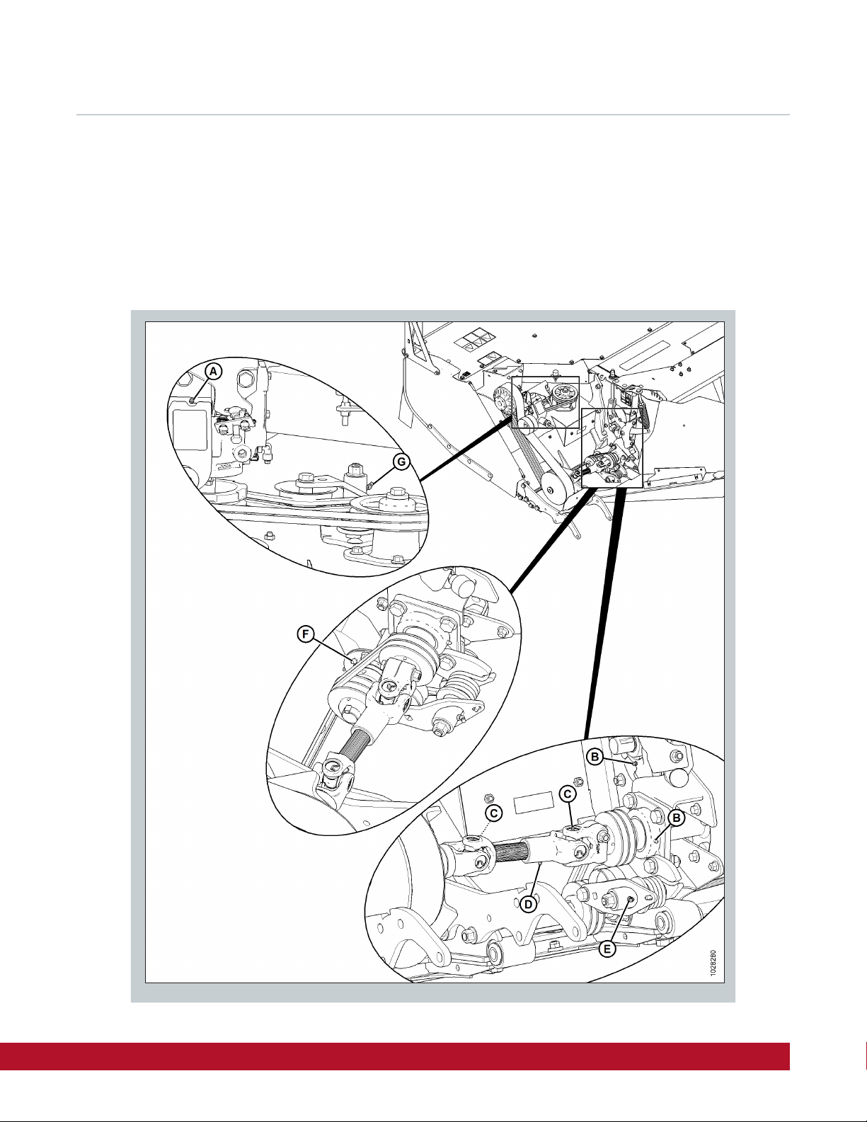
Checking Conditioner Drive Belt Tensioner ...........................................3
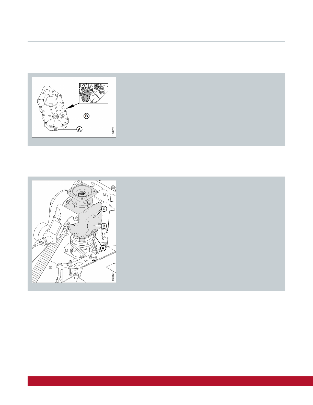
Checking Conditioner Drive Gearbox Lubricant .......................................3
Changing Conditioner Drive Gearbox Lubricant.......................................4
Changing Header Drive Gearbox Lubricant ...........................................4
Lubrication Locations ................................................................5
Left Side Every 25 hours .............................................................5
Right Side Every 25 hours............................................................6
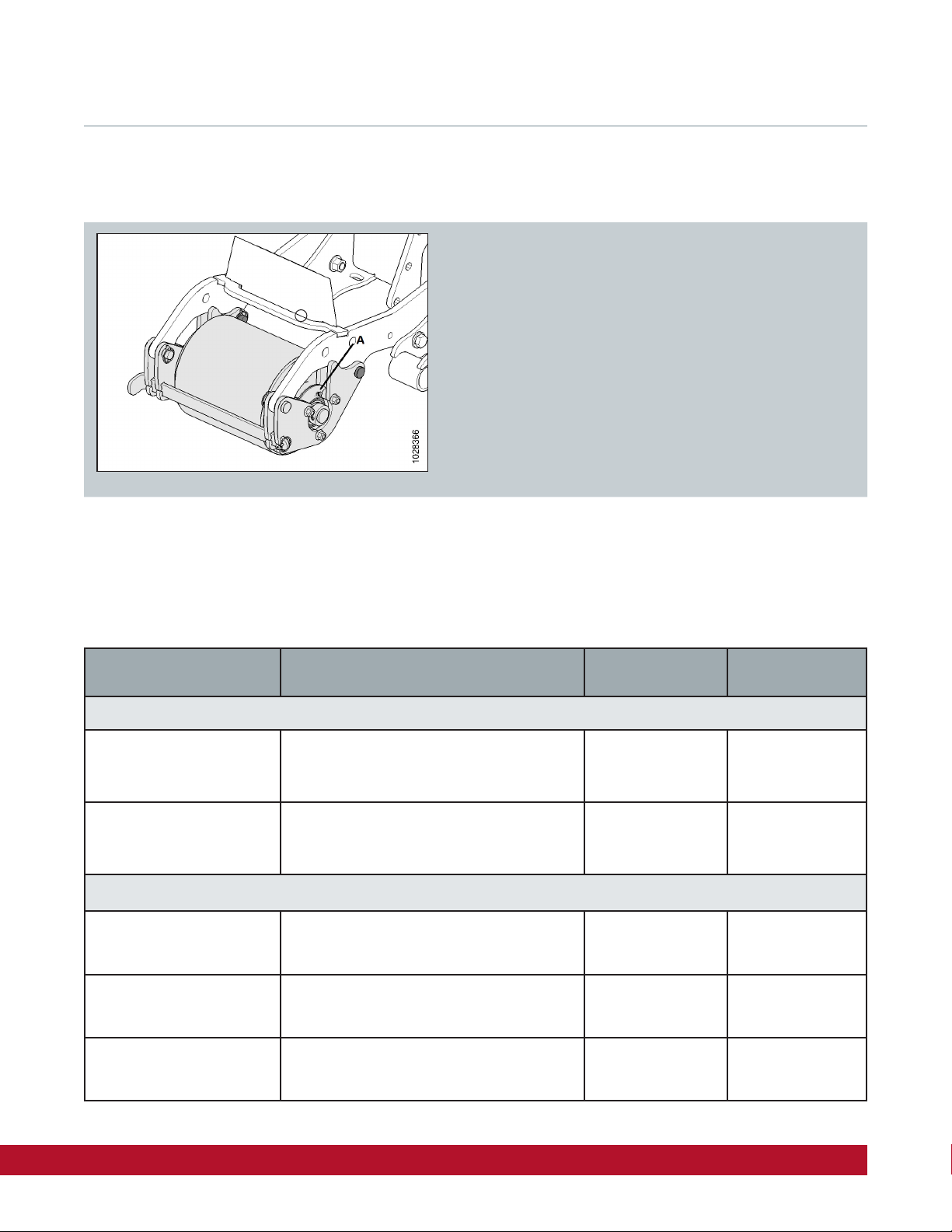
Lubrication Locations (Gauge Rollers) ...............................................7
Recommended Lubricants ..........................................................7
Cutterbar Components ...............................................................8
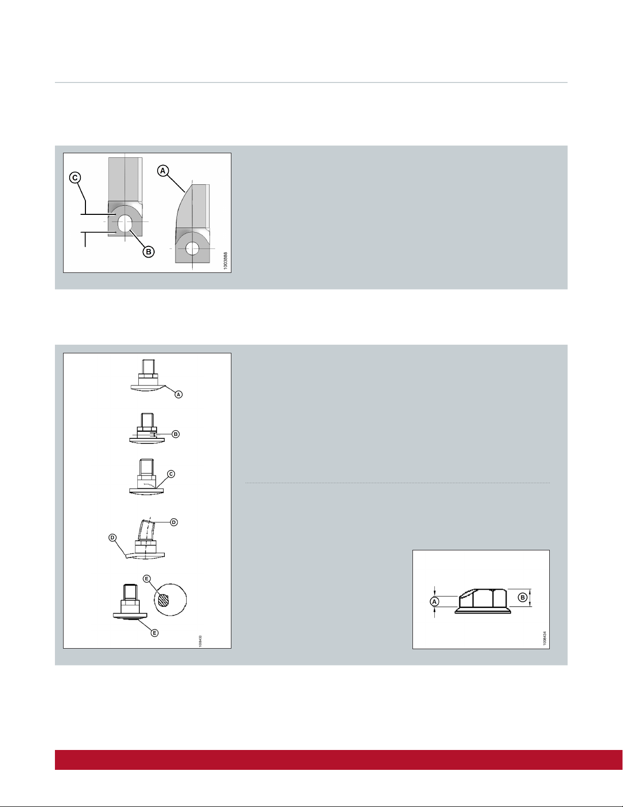
Disc Blades..........................................................................8
Disc Blade Hardware ................................................................8
Removing / Installing Disc Blades....................................................9
Settings .............................................................................10
Conditioner Roll Gap ...............................................................10
Forming Shields ....................................................................10
Manual Rear Bae..................................................................11
Positioning Rear Bae Deflector Fins ................................................11
In-Cab Electric Remote Bae ......................................................12
Recommended Starting Settings with a DWA .......................................12
Setting Header Float ...............................................................13
Performance Options................................................................14
Tall Crop Divider Kit ................................................................14
Adjustable Gauge Roller Kit.........................................................14
Adjustable Skid Shoes Kit ..........................................................15
In-Cab Electric Remote Bae Kit ...................................................15
R2 Maintenance Schedule...........................................................16
M1240 Windrower ................................................................... 17
Break-in Inspection................................................................. 17
M1240 Maintenance Chart...........................................................18

R2 Series Clinic Handout 3
Break-In Inspections
Checking Conditioner Drive Belt Tensioner
Checking Conditioner Drive Gearbox Lubricant
Measure the length of the belt tensioner spring (A)
and ensure spring length (B) is 53 mm (2 3/32 in)
Open the 2 drive shields on RH side of header.
Oil should be level with the top of the sight glass (A).
Fill as required through breather (B).
Inspection Interval Item
1 Hour Check for loose hardware and tighten to required torque
5 Hours Check for loose hardware and tighten to required torque
5 Hours Check conditioner drive belt tension
50 Hours Check conditioner drive belt tension
50 Hours Change conditioner drive gearbox lubricant
50 Hours Change header drive gearbox lubricant

4 R2 Series Clinic Handout
Break-In Inspections
Changing Conditioner Drive Gearbox Lubricant
Changing Header Drive Gearbox Lubricant
Place a 1 liter (1 Qt.) container underneath the gearbox at plug (A).
Remove plug to drain.
Fill through breather until oil is level with top of sight glass (B).
Locate gearbox on LH side of header.
Place a 4 liter container under drain (A) and remove plug at (A).
Allow oil to drain out of gearbox.
Fill oil at (C) until oil level is at check plug (B).

R2 Series Clinic Handout 5
Lubrication Locations
Left Side Every 25 hours
A - Idler/Tensioner Pivot B- Bearing, Roller Conditioner (2 Places) C- U-Joint, Conditioner Driveline (2 Places)
D- Slip Joint, Conditioner Driveline ** E- Idler/Tensioner Pivot F- Bearing, Feed Roll
G- Tensioner Arm
** Note: Use high-temperature, extreme-pressure (EP2) performance grease with 10% max molybdenum disulphide (NLGI grade 2) lithium base.

6 R2 Series Clinic Handout
Lubrication Locations
Right Side Every 25 hours
A- Bearing, Roller Conditioner (2 Places) B- U-Joint, Upper Driveline (2 Places) C- Slip Joints, Conditioner Drivelines**
D- U-Joint, Lower Driveline (2 Places) E- Idler Pivot
** Note: Use high-temperature, extreme-pressure (EP2) performance grease with 10% max molybdenum disulphide (NLGI grade 2) lithium base.

R2 Series Clinic Handout 7
Lubrication Locations (Gauge Rollers)
Recommended Lubricants
If installed, grease gauge rollers every 25 hrs (A)
2 locations per roller.
Specifications Description Use Capacities
Lubricant: Grease
SAE Multipurpose
High temperature extreme pressure (EP) perfor-
mance with 1% max. Molybdenum Disulphide (NLGI
Grade 2) lithium base
As required unless
otherwise specified.
SAE Multipurpose
High temperature extreme pressure (EP) perfor-
mance with 10% max. Molybdenum Disulphide
(NLGI Grade 2) lithium base
Driveline slip-joints
Lubricant: Gear Lubricant
SAE 80W-90 High thermal and oxidation stability API
service class GL-5 4.9 m (16 ft.) cutterbar 10 liters (10.5 qts
[US])
SAE 85W-140 Gear lubricant API service class GL-5 Conditioner drive
gearbox
0.7 liters (0.75 qts
[US])
SAE 80W-140 Fully Synthetic Oil API GL-5 Minimum,
SAE J2360 Preferred
Header drive
90 degree gearbox
1.65 liters (1.74 qts
[US])
Important:
Do NOT overfill the cutterbar when adding lubricant. Overfilling could result in overheating and failure of cutterbar components.

8 R2 Series Clinic Handout
Cutterbar Components
Check daily to ensure that disc blades are securely attached to the disc.
Change disc blades when they show cracks, signs of wear (A) and/or an
elongated hole (B) beyond safe operating limits (C). Max elongation is
21mm (13/16 in)
Disc Blades
Disc Blade Hardware
Check and replace bolt if:
Bolt has been removed and installed five times
Head (A) is worn flush with bearing surface of blade
Diameter of bolt neck is worn (B) 3mm (1/8 in)
Bolt is cracked (C)
Bolt is visibly distorted (D)
Bolt shows evidence of interference (E) with adjacent parts
Check and replace nut if:
Nut has been previously installed – nuts are one-time use only
Nut shows signs of wear (A below)
that is more than half the original
height (B below)
Nut is cracked

R2 Series Clinic Handout 9
Removing / Installing Disc Blades
Rotate disc (A) so blade (B) lines up with the hole (C) in the rock guard.
Place a pin or equivalent in the front hole of the neighboring rock guard
to prevent disc rotation while loosening blade bolts.
Install new or flipped/reversed blade (A) with shoulder bolt (B)
onto disc (C)
Install new nut (D) and torque to 125 Nm (92lbf-ft)
Remove nut (A) and discard
Important:
Nuts are one-time use only. When flipping or changing a blade, replace
using a NEW nut,
Remove shoulder bolt (B) and blade (C)
Important:
Blades should be replaced in pairs or the disc may become unbalanced and cause damage to the cutterbar.
The disc blades have cutting edges on both sides so the blades can be turned over and re-used.

10 R2 Series Clinic Handout
Settings
1. Loosen jam nut (A) on both sides of the conditioner. Turn lower
bolt (B) counterclockwise until the upper roll rests on the lower roll.
Ensure the rolls inter-mesh.
2. Turn lower nut (B) two and a half turns counterclockwise to raise
the upper roll and achieve a 6 mm (1/4 in) roll gap.
3. Hold nut (B) and tighten jam nut (A) on both sides of the conditioner.
4. If further adjustment to roll gap is required:
Turn lower nut (B) clockwise to increase roll gap.
Turn lower nut (B) counterclockwise to decrease roll gap.
Set forming shield side deflectors (A) to the desired width by repositioning
adjuster handle (B). To ensure windrow placement is centered, adjust both
side deflectors to the same position.
Conditioner Roll Gap
Forming Shields
Important:
Make sure the roll gap adjustment nuts are adjusted equally on both sides of the disc header to achieve a consistent gap
across the rolls.

R2 Series Clinic Handout 11
Manual Rear Bae
1. Remove lynch pin (A) securing rear bae adjustment lever (B)
to bracket (C).
2. Pull rear bae adjustment lever (B) inboard to disengage
from bracket (C).
3. Position rear bae adjustment lever (B) as follows:
• Move the lever forward to raise the bae
• Move the lever backward to lower the bae
4. Release rear bae adjustment lever (B) so that the tab engages
the hole in bracket (C).
5. Secure bae adjustment lever (B) with lynch pin (A).
1. Deflector fins (A) are located on the underside of the rear bae.
2. To adjust deflector fins (A), use existing bolt and nut (B).
Once adjusted to the desired angle for windrow width, torque nut to 69 Nm
(51 lbf·ft).
3. Repeat for all fins
Positioning Rear Bae Deflector Fins
Note:
An optional In-Cab Electric Remote Bae Adjustment Kit (B6664) is available for R216 headers.
Note:
Fins may interfere with crop flow in large-stemmed crops,
or when using the double windrower attachment. It may be
necessary to remove fins in these conditions.
Deflector fins (A) can be put in storage position by removing
existing nut and bolt and reattaching fins on top of the bae.

12 R2 Series Clinic Handout
Settings
1. If the In Cab Remote Bae is installed, the bae is controlled inside the
windrower cab by buttons F5 (A) (bae up) and F6 (B) (bae down).
No set-up is required on the display to activate controls.
2. A pop up will appear on the display for 3 seconds indicating bae
position from 0 – 10.
In-Cab Electric Remote Bae
Recommended Starting Settings with a DWA
Important:
Confirm that bae can move freely through its range of motion and does not contact side deflectors.
1. DWA adjusted low and close to the RH tire
2. Tall crop feed plates installed
3. Rear bae deflector fins removed
4. Forming shield top deflector fins removed. RH side deflector positioned straight back. LH side
deflector angled so that crop lands on the DWA.
5. Tight conditioner roll gap (for crop conditions)
6. Minimum disc speed of 2100 rpm
7. Ensure right side of header is full (more than 10” of overlap will dramatically aect crop flow)
8 Header angle and bae angle are key. Start with a mid position header tilt (4-7). Ensure the crop is
dropping fully onto the DWA. Too steep of a header angle and the crop will hit the forming shield too
early, too shallow and the crop will not arc up towards the DWA. Use the rear bae angle to adjust
how the crop is flowing into the forming shield.
9. Enter crop at relatively high speed 8 km/h+ (5 mph+)
10. Maintain consistent ground speed for consistent crop flow

R2 Series Clinic Handout 13
1. Use the Header Tilt switches (A) on the ground speed lever (GSL)
to set the center-link to the mid-position (5.0 on the monitor)
2. Using the header down button (B), lower the header fully and ensure
the header lift cylinders are fully retracted.
3. Grasp one end of the header and lift. The force required to lift the
header should be 426 – 471 N (95 – 105 lbf).
The force required to lift the header should be equal on either side.
If adjustments to float are required
4. Press rotary scroll knob (A) on the HPT (monitor) to display the
QuickMenu system.
5. Rotate scroll knob (A) to highlight header float icon (B) and press
scroll knob to select.
6. Turn scroll knob (A) to highlight left (B) or right (C) float and press
knob (A) to activate selection.
7. Rotate scroll knob (A) to adjust float setting and press knob when
finished. Float is now set.
8. Use softkey 3 (D) to remove/resume float to previous setting when
attaching or detaching the header.
Setting Header Float
Note:
Float adjustments of 1.0 (out of 10) change the header weight at the cutterbar by approximately 91 kg (200 lb.).
Adjust float in increments of 0.05 to optimize field performance.
Too heavy float causes skid shoe wear, too light float causes excessive header bouncing over uneven terrain.

14 R2 Series Clinic Handout
Performance Options
Tall Crop Dividers attach to the ends of the self-propelled disc
header for clean crop dividing and cutterbar entry in tall crops.
The kit (MD #B6665) includes left and right dividers and
attachment hardware.
The Adjustable Gauge Roller kit (MD #B6666) allows the
R216 Rotary Disc Header to achieve the desired cutting height
for optimum cutting performance.
Tall Crop Divider Kit
Adjustable Gauge Roller Kit
Note:
For use on dry, hard ground or in sandy conditions.

R2 Series Clinic Handout 15
The Adjustable Skid Shoes kit (MD #B6667) allows the
R216 Rotary Disc Header to achieve the desired cutting
height for optimum cutting performance.
The In-Cab Electric Remote Bae kit (MD #B6664), allows the operator
to adjust the disc header bae electronically from inside the windrower.
Adjustable Skid Shoes Kit
In-Cab Electric Remote Bae Kit
Note:
For use in most ground conditions including wet or muddy ground.

16 R2 Series Clinic Handout
First 10 Hours, Then Daily
Inspect cutterbar discs. Refer to Inspecting
Cutterbar Discs, page 76
Inspect discblades. Refer to Inspecting Discblades,
page 87
Inspect accelerators. Refer to Inspecting
Accelerators, page 93
Inspect rock guards. Refer to Inspecting
Rock Guards, page 97
Inspect drums. Refer to Inspecting
Drums, page 100
Check hydraulic hoses and lines. Refer to 4.12.1
Checking Hydraulic Hoses and Lines, page 151
Every 25 Hours
Check conditioner drive belt tension. Refer to
Inspection Conditioner Drive Belt, page 134
Lubricate idler pivot. Refer to 4.4 Lubrication,
page 68
Lubricate upper and lower driveline universal joints.
Refer to 4.4 Lubrication, page 68
Lubricate roller conditioner and feed roller bearings.
Refer to 4.4 Lubrication, page 68
Lubricate conditioner driveline. Refer to 4.4
Lubrication, page 68
Every 100 Hours or Annually
Check conditioner drive belt tension. Refer to
Inspection Conditioner Drive Belt, page 134
Check roll timing gearbox lubricant. Refer to 4.6.1
Checking and Changing Conditioner Roll Timing
Gearbox Oil, page 124
Check header drive gearbox lubricant. Refer to 4.7.1
Checking Header Drive Gearbox Oil, page 127
Every 250 Hours
Change roll timing gearbox lubricant. Refer to
4.6.1 Checking and Changing Conditioner Roll Timing
Gearbox Oil, page 124
Change header drive gearbox lubricant. Refer to
4.7.2 Changing Header Drive Gearbox Oil, page 129
Change cutterbar lubricant. Refer to 4.5.1
Lubricating cutterbar, page 71
Lubricate left and right driven drums. Refer to
Removing Left Driven Drum and Driveline, page 105 &
Removing Right Driven Drum and Driveline, page 110
R2 Maintenance Schedule
The pages referenced below can be found in the Operator’s Manual
Action Check Lubricate Change

R2 Series Clinic Handout 17
M1240 Windrower
Break-in Inspection
The table below can be referenced in the M1240 Operator’s Manual
Inspection Interval Item Check
1 Hour Drive wheel nuts
Torque: 510 Nm (375 lbf·ft) dry
Repeat checks at one hour intervals until torque stabilizes
at two consecutive checks
5 Hour A/C compressor belt Tension
5 Hour Caster wheel nuts Torque: 170 Nm (125 lbf·ft)
5 Hour Caster wheel anti-shimmy dampener bolts
Inboard bolt torque: 136 Nm (100·lbf·ft)
Outboard bolt torque: 244 Nm (182 lbf·ft)
Outboard jam nut: 136 Nm (100 lbf·ft)
5 Hour Walking beam width adjustment bolts Torque: 759 Nm (560 lbf·ft)
10 Hour Walking beam width adjustment bolts Torque: 759 Nm (560 lbf·ft)
50 Hour Drive wheel nuts
Torque: 510 Nm (375 lbf·ft) dry
Repeat checks at one hour intervals until torque stabilizes
at two consecutive checks
50 Hour Hose clamps: air intake / radiator / heater / hydraulic Hand-tighten unless otherwise noted
50 Hour Walking beam width adjustment bolts Torque: 759 Nm (560 lbf·ft)
50 Hour Caster wheel nuts Torque: 170 Nm (125 lbf·ft)
50 Hour Caster wheel anti-shimmy dampener bolts
Inboard bolt torque: 136 Nm (100·lbf·ft)
Outboard bolt torque: 244 Nm (182 lbf·ft)
Outboard jam nut: 136 Nm (100 lbf·ft)
50 Hour Engine gearbox oil Change
50 Hour Drive wheel lubricant Change
50 Hour Charge system oil filter Change

18 R2 Series Clinic Handout
M1240 Maintenance Chart
The table below can be referenced in the M1240 Operator’s Manual
Maintenance Record Action Check Lubricate Change Clean Add
Hour meter reading
Date
Serviced by
FIRST USE, refer to 5.2.1 Break-in Inspection Schedule, page 264
10 Hours or Daily14
Engine oil level15
Engine gearbox oil level15
Engine coolant level at reserve tank15
Fuel Tank15
Drain fuel filter water trap15
Hydraulic hoses and lines for leaks15
Hydraulic oil level15
Tire inflation15
Diesel exhaust fluid (DEF) level15
Annually16
A/C blower
Antifreeze concentration
Battery charge
Battery fluid level
Steering linkages
50 Hours
Cab fresh air intake filter
Caster pivots
Forked caster wheel bearings
Top lift link pivots on lift arms (2 places
on both sides [x4])
100 Hours or Annually 14, 16
A/C condenser
Change air cooler
Hydraulic oil cooler
Radiator
Cab air return filter

R2 Series Clinic Handout 19
250 Hours or Annually 14, 16
Engine oil and filter
Engine air cleaner primary filter element
Single-sided caster wheel hub bearings
Drive wheel lubricant level
Mud caster wheel hub bearings
Exhaust system (visually inspect for leak-
age point, loose clamps or loose hose)
Engine gearbox oil
500 Hours or Annually 14, 16
Primary and secondary fuel filters
Hydraulic return filter and change filter
Safety systems
1000 Hours
DEF supply module filter
1000 Hours or Annually 14
Fuel tank vent line filter
Wheel drive lubricant
2000 Hours
Crankcase breather filter and gasket
DEF tank vent hose filter

MD-1000C2 R2 Series Clinic Handout - 4/5/2020
This manual suits for next models
2
Table of contents
Other MacDon Farm Equipment manuals

MacDon
MacDon M1170 User manual

MacDon
MacDon M155 User manual

MacDon
MacDon Swath Compressor Guide

MacDon
MacDon 963 User manual

MacDon
MacDon FlexDraper FD2 Series User manual

MacDon
MacDon M205 2010 User manual

MacDon
MacDon FD75 User manual

MacDon
MacDon D1X Series User manual

MacDon
MacDon M155E4 User manual

MacDon
MacDon A30-D User manual

MacDon
MacDon R85 User manual

MacDon
MacDon 973 User manual

MacDon
MacDon PW8 User manual

MacDon
MacDon R216 User manual

MacDon
MacDon FlexDraper FD1 Series User manual

MacDon
MacDon M155 User manual

MacDon
MacDon FD75 User manual

MacDon
MacDon 9000 User manual

MacDon
MacDon R85 User manual

MacDon
MacDon R85 User manual