Orthman 1tRIPr User manual

1tRIPr XD
Operator’s Manual
Part #125-024-01

INTRODUCTION
Built for today’s larger farms, the drawn Orthman 1tRIPr® XD oers the additional eciency of fertilizer carrying capacity integrated in
large-frame drawn designs. The Orthman 1tRIPr® XD is a great addition to the modern high horsepower farms.
12 row 1tRIPr XD
The Orthman 1tRIPr® XD comes standard with Orthman 1tRIPr® row units and can be equipped with either a 1,000 gallon liquid fertilizer package,
a 6 or 9 ton dry fertilizer package, or the stand alone carrier (standard). For information regarding the specic fertilizer package on your machine,
refer to the tooling options section of this manual. For information regarding the 1tRIPr® row units, refer to the 1tRIPr® operator’s manual.
This manual is considered to be an integral component of the 1tRIPr®
XD
and is designed to educate the owner and/or operator(s) regarding safety,
operation, maintenance, troubleshooting, and component identication. All personnel involved in the operation of this implement are responsible
for reading and understanding entire manual content. This manual is designed to keep the operator safe and knowledgeable as well as prolong the
life of the implement and maximize eld eciency. This manual should accompany the implement if it were ever to be sold.
We would like to thank you for placing your condence in Orthman Mfg., Inc. Your 1tRIPr®
XD
is manufactured to meet the highest standards and is
built with precision and strength to increase your agricultural operation’s dependability and protability.
Thank you for choosing Orthman.
1-1

INTRODUCTIONINTRODUCTION
To The Dealer:
Inspect the implement thoroughly after assembly to be certain it is functioning properly before delivering it to the customer. The
following checklist is a reminder of points to cover. Check o each item as it is found satisfactory or after proper adjustment is
made.
Pre-Delivery Checklist
1. All Hardware properly tightened.
2. Lubrication of grease ttings.
3. All decals properly located and readable.
4. All implement tools and options are installed and set.
5. Check overall condition of implement.
6. Make sure Operator’s manual is included.
Date Set Up. Signature.
Delivery
Review the operator’s manual with the customer. Explain the following:
1. Introduce the machine to the customer. Give the customer this manual and encourage them to read it.
2. Make the customer aware of all the safety precautions that must be exercised when using and transporting this
machine.
3. Make customer aware of the dierent tooling options available.
4. This machine does not come set to run in the eld from the factory. The Field settings section in this manual is
meant to help set the machine for optimal performance. Explain all operating adjustments.
5. Explain to the customer that the life expectancy of this machine depends on regular maintenance as directed in
this manual.
6. Tell the customer to use the proper tools for service and make them aware of Orthman parts availability.
7. Write machine model number and serial number in the spaces provided below.
Date delivered. Signature.
Model Number.
Serial Number.
1-2

INTRODUCTION INTRODUCTION
TABLE OF CONTENTS
INTRODUCTION
General Information -
1tRIPr
®
XD
....................................................................................................................................................1 - 1
Warranty Information ....................................................................................................................................................................1 - 2
Delivery Checklist...........................................................................................................................................................................1 - 3
Table of Contents ............................................................................................................................................................................1 - 4
IMPORTANT SAFETY INFORMATION
Farm Safety.....................................................................................................................................................................................2 - 1
Your Protection - Equipment Safety - Safety Alert Symbol ............................................................................................................2 - 3
Signal Words - Shutdown and Storage ...........................................................................................................................................2 - 4
Safe Transport - Warning and Safety Lights...................................................................................................................................2 - 5
Safe Operation - No Riders..............................................................................................................................................................2 - 6
Practice Safe Maintenance..............................................................................................................................................................2 - 7
Practice Safe Maintenance - Prepare for Emergencies ...................................................................................................................2 - 8
Anhydrous Ammonia - Liquid Fertilizer Precautions - Safety Never Hurts .....................................................................................2 - 9
Safety Decals ................................................................................................................................................................................2 - 10
Orthman Decals and Orthman Serial Tag......................................................................................................................................2 - 14
PREPARATION AND SETUP
Toolbar Component Identication..................................................................................................................................................3 - 1
Narrow Transport Toolbar Component Identication.....................................................................................................................3 - 2
Tongue Component Identication..................................................................................................................................................3 - 3
Carrier Component Identication...................................................................................................................................................3 - 4
Light Kit Component Identication................................................................................................................................................3 - 5
Shipping Conguration...................................................................................................................................................................3 - 6
Preparing the Machine - Machine to Tractor Connection ...............................................................................................................3 - 7
TOOLING OPTIONS
Tongue Tab .....................................................................................................................................................................................4 - 1
Fertilizer Packages (Liquid Fertilizer) .............................................................................................................................................4 - 2
Fertilizer Packages (Dry Fertilizer)..................................................................................................................................................4 - 3
Additional Options (Scale Kit, Nurse Tank Hitch) ............................................................................................................................4 - 4
SMART IMPLEMENT GUIDANCE
Component Identication...............................................................................................................................................................5 - 1
Preparation and Set-Up - Preparation for Use................................................................................................................................5 - 2
Calibration...............................................................................................................................................................................5 - 3
Hydraulics.......................................................................................................................................................................................5 - 6
FIELD SETTINGS
Field Operation................................................................................................................................................................................6 - 1
Bar Stand Placement................................................................................................................................................................6 - 1
Rigid Operation - Wing Leveling ..............................................................................................................................................6 - 2
Narrow Transport Toolbar Stands.............................................................................................................................................6 - 3
Toolbar Height and Orientation.......................................................................................................................................................6 - 4
NT Toolbar Folding Process..............................................................................................................................................................6 - 5
1-4
INTRODUCTION
WARRANTY
Orthman warrants each new wholegood product to be free from defects in manufactured components and workmanship. This warranty is applicable only
for the normal service life expectancy of the product or components, not to exceed twenty-four (24) consecutive months from date of purchase of the new
Orthman product to the original purchaser.
Purchased components installed by Orthman (blades, bearings, controls, hoses, wheels, coulters, cylinders, ttings, etc.) shall be warranted by the
respective manufacturer for a period of twelve (12) consecutive months from date of delivery of the new Orthman product to the original purchaser.
A completed online Warranty Registration for the original purchaser must be received by Orthman to activate warranty coverage. Non-receipt of warranty
registration may void warranty coverage. The Orthman warranty is non-transferable.
Genuine Orthman replacement parts and components will be warranted for ninety (90) days from date of purchase, or the remainder of the original
equipment warranty period, whichever is greater.
All warranty work is to be performed by an authorized Orthman dealer at the repairing dealer’s location, unless otherwise approved by Orthman.
Under no circumstances, will this warranty cover any merchandise or component thereof, which, in the opinion of Orthman, has been subjected to misuse,
unauthorized modications or alteration, accident, collision with obstruction/ground, or if repairs have been made with parts other than those obtainable
through Orthman.
Orthman warranty policies do not cover travel expenses, after-hours eld/service time, overnight expenses, or expenses not related to regular shop labor
rates or parts replaced during actual warranty repair. Orthman reserves the right to adjust warranty labor credits to believed normal repair times as
directed by state law(s).
This warranty shall be limited to repairing or replacing, free of charge to the purchaser, any part, which Orthman’s judgment shows evidence of such defect.
Additionally, the defective part(s) shall be returned within thirty (30) days from the date of failure to Orthman through the dealer or distributor from whom
the product was purchased or repaired; transportation charges prepaid.
This warranty shall not be interpreted to render Orthman liable for injury or damages of any kind or nature to person or property. This warranty does not
extend to the loss of crops, loss of delay in harvesting/planting, or any expense or loss incurred for labor, substitute machinery, rental, or any subsequent
reasons thereof.
Except as set forth above, Orthman shall have no obligation or liability of any kind on account of its equipment and shall not be liable for special or
consequential damages. Orthman makes no other warranty, expressed or implied, and, specically disclaims any implied warranty or
merchantability or tness for a particular purpose. Some states or provinces do not permit limitations or exclusions of implied warranties or
incidental or consequential damages, so the limitations or exclusion in this warranty may not apply. This warranty is subject to any existing conditions of
supply, which may directly aect ability to obtain materials or manufacture replacement parts.
Orthman reserves the right to make improvements in design or changes in specications at any time, without incurring any obligation to owners of
units previously sold; to include, but not limit to engineering prototype machines. No one is authorized to alter, modify, or enlarge this warranty nor the
exclusions, limitations, and reservations.
© Copyright 2014
Orthman Manufacturing Inc.
Lexington, Nebraska
All rights reserved.
Orthman provides this manual without warranty of any kind, expressed or implied. This manual
reects the product at the time of publication. All information within is based upon current
information on the publication date. Orthman assumes no responsibility for damages incurred due
to the use of the illustrations, information, and specications within this publication.
1-3

SAFETY INFORMATION
INTRODUCTION
Farm Safety
Contraryto the popular image of fresh air andpeaceful surroundings, a farm is not a hazard-freework setting.
Everyyear, thousands of farm workers are injured andhundreds more die in farming accidents. According tothe National Safety Council, agriculture is the
mosthazardous industry in the nation.
How You Can Improve Farm Safety
You can start by increasing your awareness of farming hazards and making a conscious effort to prepare for emergency situations including res, vehicle
accidents,electrical shocks from equipment and wires, and chemicalexposures. Be especially alert to hazards that mayaffect children and the elderly.
Minimizehazards by carefully selecting the products you buyto ensure that you provide good tools andequipment. Always use seat belts when operating
tractors,and establish and maintain good housekeeping practices. Hereare some other steps you can take toreduce illnesses and injuries on the farm:
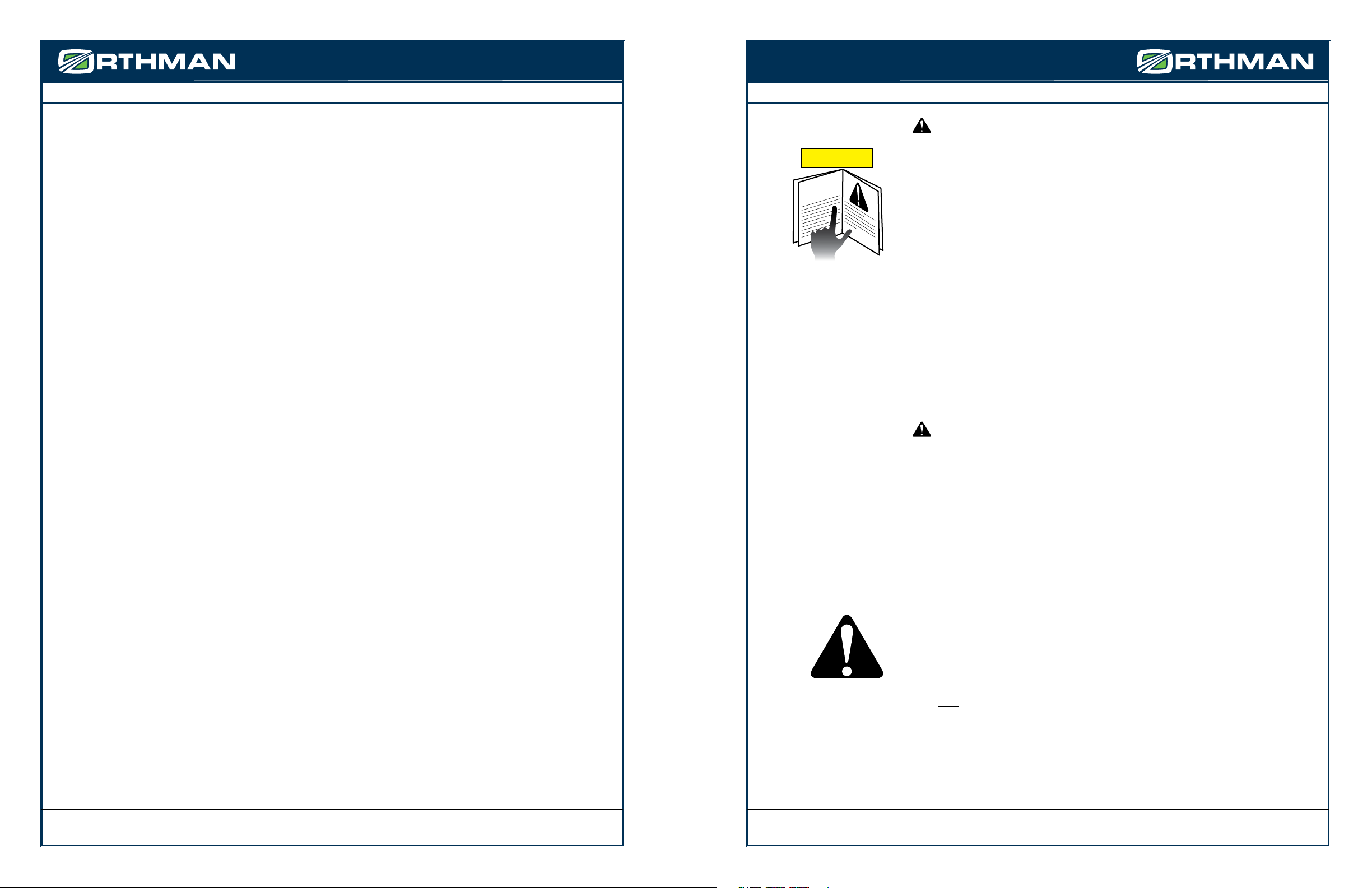
•Read and follow instructions in equipment operator’s manualsand on product labels.
•Inspect equipment routinely for problems that may causeaccidents.
•Discuss safety hazards and emergency procedures with yourworkers.
•Install approved rollover protective structures, protective enclosures, orprotective frames on tractors.
•Make sure that guards on farm equipment arereplaced after maintenance.
•Review and follow instructions in material safety datasheets (MSDSs) and on labels that come withchemical products
and communicate informationon these hazards to your workers.
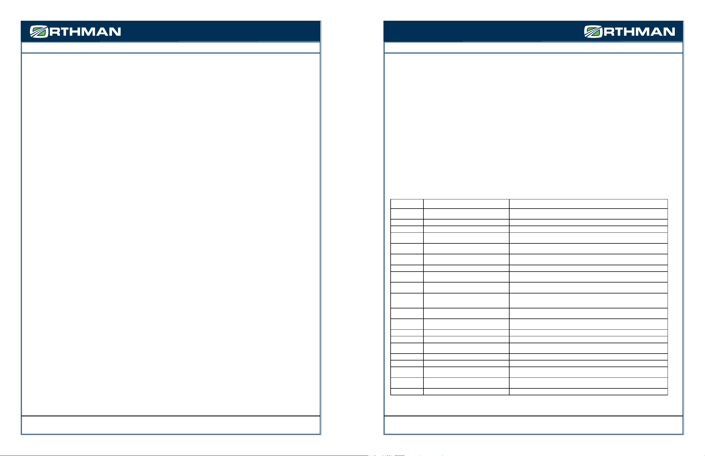
Health and Safety Hazards on Farms
Farmworkers including farm families and migrant workers areexposed to hazards such as the following:
Danger Potential Effect or Injury Prevention
Chemicals/Pes-
ticides
Skinand respiratory injury or death MSDS and proper Personal Protective Equipment. Review Manufacturers data sheets
Cold Illness,Frostbite or death Dressproperly for the day.
Dust Respiratoryinjury or explosive combinations Be aware of your surroundings and activity
Electricity Shock, burns, re, death Use a qualied professional for wiring dangerous electrical devices. Never overload a circuit. Replace
damagedelectrical devices or cords. Electrical tape will not insulate you from injury.
Grainbins, Silos Entrapment, Suffocation, Explosion from formation of
dangerousgases and poisoning.
Makesure the bin is properly ventilated and maintained. Never walk the grain.
Handtools Injury including cuts abrasions, electrocution, strains,
sprainsand death
Makesure you hand tools are in good condition. Never leave a damaged tooling accessible forsomeone
elseto use.
Highway trafc Collisionsresulting in injury or death Followregulations, stay alert. Avoid alcohol and use of communication devices while driving
Lifting& lifting
devices
Backinjury, sprains, strains. Falling material resulting
inbeing struck or crushed by heavy material
Useproper lifting technique. Get help when the load is too heavy. Inspect chains, straps or cablesroutine-
lyto make sure they are in good condition.
Livestockhandling Serious injury or death resulting from being pinned
struckor trampled.
Alwaysmake sure you have adequate room and an escape route
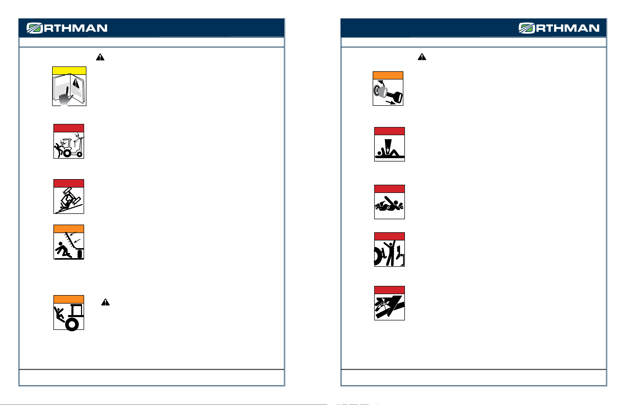
Machinery/Equip-
ment
Cuts,abrasions, amputations, death. Thoroughlyread and understand your Owners Equipment Manual. Never operate the equipment without
guardsin place. Make sure the equipment can not be energized or otherwise put into operationwhileyou
areworking on it.
Manurepits Explosionfrom formation of dangerous gases. Suffo-
cation. Poisoning
Propermaintenance.
Mud Sprains,strains, entrapment and suffocation. Eye
injuryand skin irritation.
ProperPersonal Protective Equipment. In some conditions a “Spotter” may be needed.
Noise Hearingdamage PersonalProtective Equipment.
Ponds Drowning Weara life preserver and make sure help is readily available.
Slips/Trips/Falls Sprains,strains, back and neck injury, bone breaks
ordeath
Keepwork area free from clutter and organized. If working on anything elevated make sure youhave
appropriateguarding and/or fall protection such as a harness and lanyard.
Sun/Heat Sunburn, Heat Stroke, shock, death Usecommon sense on excessively hot days, use sun screen, wear a hat and stayhydrated.
Toxicgases Skin and respiratory injury or death. Explosion. MSDSand proper Personal Protective Equipment. Review Manufacturers data sheets
Tractors Cuts,abrasions, amputations, death. Thoroughlyread and understand your Owners Equipment Manual. Never operate the equipment without
guardsin place. Anti-roll over devices.
Wells Electrocution,amputation, death Avoidcontact with water while working on an electrical device. Always be sure the equipment can/willnot
beenergized during repair or maintenance. Make sure all guarding is in place.
SevereWeather Electrocution,“struck by” injuries, death Moveto a safe place. Lightening, hail and tornadoes are unpredictable.
OrthmanManufacturing, Inc. does not limit the potential effects or injuries nor prevention measures to those listed above. Theyare providedsolely
as a guideline to making your farm life safer. Always consult your Owner/Operators Manual for specic tool and equipment safety requirements.
2-1
TABLE OF CONTENTS
HYDRAULICS
Standard Manifold Block Identication...........................................................................................................................................7 - 1
NT Manifold Block Identication.....................................................................................................................................................7 - 2
Standard Machine Fold Hydraulic Hose Routing .............................................................................................................................7 - 3
Machine Lift Hydraulic Hose Routing..............................................................................................................................................7 - 4
NT Machine Fold Hydraulic Hose Routing........................................................................................................................................7 - 5
TROUBLESHOOTING
Toolbar will not fold or unfold.........................................................................................................................................................8 - 1
Removal of internal cylinder assembly ...........................................................................................................................................8 - 3
Machine will not raise or lower.......................................................................................................................................................8 - 5
MAINTENANCE
Practice Safe Maintenance..............................................................................................................................................................9 - 1
Torque Specications......................................................................................................................................................................9 - 2
Lubrication .....................................................................................................................................................................................9 - 3
Implement Inspection ....................................................................................................................................................................9 - 6
Implement Storage.........................................................................................................................................................................9 - 7
PARTS IDENTIFICATION
Tongue Assembly ..........................................................................................................................................................................10 - 1
Toolbar Hinge Assembly................................................................................................................................................................10 - 3
Toolbar Center Section Assembly..................................................................................................................................................10 - 4
Narrow Transport Toolbar Center Section Assembly .....................................................................................................................10 - 5
Carrier Assembly ...........................................................................................................................................................................10 - 7
NT Outer Wing Hinge Assembly ....................................................................................................................................................10 - 9
Small Wheel and Axle Package ...................................................................................................................................................10 - 11
Large Wheel and Axle Package ...................................................................................................................................................10 - 12
Camoplast TTS 30-1601 Track Package........................................................................................................................................10 - 13
Camoplast TTS 45-1811 Track Package........................................................................................................................................10 - 14
Standard Internal Fold Assembly ................................................................................................................................................10 - 15
NT Mid-Wing Internal Fold Assembly..........................................................................................................................................10 - 16
NT Outer Wing Fold Linkage Assembly........................................................................................................................................10 - 17
Hydraulic Cylinder (Wing Fold)....................................................................................................................................................10 - 19
Hydraulic Cylinder (Machine Lift)................................................................................................................................................10 - 20
Standard Hydraulic Manifold Assembly ......................................................................................................................................10 - 21
NT Hydraulic Manifold/Gear Flow Divider Assembly ...................................................................................................................10 - 22
Hydraulic Hose Identication - Standard Wing Fold ...................................................................................................................10 - 23
Hydraulic Hose Identication - Narrow Transport Wing Fold......................................................................................................10 - 25
Hydraulic Hose Identication - Machine Lift...............................................................................................................................10 - 27
Smart Implement Guidance Steering Components.....................................................................................................................10 - 29
Smart Implement Guidance Steering Components.....................................................................................................................10 - 30
Steerable Wheel and Axle Assembly (Small Wheel)....................................................................................................................10 - 31
Steerable Wheel and Axle Assembly (Large Wheel) ...................................................................................................................10 - 32
Light Bracket Assembly...............................................................................................................................................................10 - 33
Light Kit Assembly ......................................................................................................................................................................10 - 34
Liquid Fertilizer Package Assembly.............................................................................................................................................10 - 35
Dry Fertilizer Package Assembly .................................................................................................................................................10 - 36
1-5

SAFETY INFORMATION SAFETY INFORMATION
FOR YOUR PROTECTION
READ AND UNDERSTAND THE ENTIRE CONTENT OF THIS
MANUAL BEFORE OPERATING OR SERVICING IMPLEMENT. Read
and understand all operator manuals for the machinery used in conjunction with your
Orthman equipment.
•Carefully READ ALL SAFETY DECALS in this manual as well as on the imple-
ment. Keep implement clean so decals are easily visible. Keep all safety decals in good,
clean, and legible condition. Immediately replace damaged and/or missing decals.
Replacement decals are available from your Orthman dealer.
• Learn to operate the implement and all components properly. Do not let others operate
implement without proper instruction. Unauthorized implement modications may
impair function and safety. If you do not understand any content in this manual or need
assistance, contact your Orthman dealer.
EQUIPMENT SAFETY GUIDELINES
Operator safety is the primary concern when designing an Orthman implement. Orthman
integrates as many safety features into the implement as possible. You can avoid many
hazards and possible accidents by observing precautions in this safety section.
• Insist that yourself and personnel working with and around you follow all safety precau-
tions. Be cautious when working with or around implement to avoid injury.
SAFETY ALERT SYMBOL
The SAFETY ALERT SYMBOL warns of potential hazards to personal safety
and that extra precautions must be taken. When you see this symbol, carefully read the
message(s) that follow. Follow all recommended precautions and safe operating practices
in this manual.
NOTE: Hazard control and accident prevention are dependent upon the safety awareness
and proper training of personnel involved in the operation of this implement.
CAUTION
OPERATOR’S
MANUAL
2-3
HighRisk Factors on Farms
Thefollowing factors may increase risk of injury orillness for farm workers:
•Age – Injury rates are highest among childrenage 15 and under and adults over 65.
•Equipment and Machinery – Most farm accidents andfatalities involve machinery. Proper machine guarding and doingequipment maintenance
accordingto manufacturers’ recommendations can help prevent accidents.
•Protective Equipment – Using protective equipment, such asseat belts on tractors, and personal protective equipment(such as safety gloves,
coveralls, boots, hats, aprons, goggles, face shields) could signicantly reduce farming injuries.
•Take precautions to prevent entrapment and suffocation causedby unstable surfaces of grain storage bins, silos,or hoppers. Never “walk the grain.”
• Be aware that methane gas, carbon dioxide, ammonia, and hydrogen sulde can form in unventilated grain silos and manure pits and can suffocate
orpoison workers or explode.
•Take advantage of safety equipment, such as bypassstarter covers, power take-off master shields, and slow-movingvehicle emblems.
•Medical Care – Hospitals and emergency medical careare typically not readily accessible in rural areasnear farms.
The Benets of Improved Safety and Health Practices
OrthmanManufacturing Provides this document in the hope thateveryone that has a job to do, doesit SAFELY. Our goal and yours should be toend
eachday in the best possible health. Better safety andhealth practices reduce fatalities, injuries, and illnesses aswell as associated costs such as
workers’compensation insurance premiums, lost production, and medical expenses.A safer and more healthful workplace improves moraleand
productivity.
2-2

SAFETY INFORMATION SAFETY INFORMATION
SAFE TRANSPORT
• Engage transport locking devices prior to transport.
• Plan your route to avoid trac. Yield to trac in all situations.
• Maximum transport speed is 20 mph (32 kph). Various conditions will require reduced
speed. Travel at speeds that allow for adequate control of stopping and steering.
AVOID ELECTROCUTION. Be aware of overhead power lines. Contact or close
proximity to power lines can result in injury or death. Use extreme care when operating
implement near power lines.
• Know implement transport height and gross weight. Avoid overhead obstructions not
allowing your transport height. Do not use bridges rated below combined implement
and tractor weight.
• Make sure a slow moving vehicle (SMV) placard is mounted to the implement and is
easily visible to other motorists.
• Make allowances for implement size when transporting. Sudden braking can cause a
towed load to swerve and/or rollover. Never use independent braking with implement in
tow as loss of control and/or rollover can result. Reduce speed if towed implement is not
equipped with brakes.
• Do not coast. Always keep tractor or towing device in gear to provide engine braking when
traveling downhill.
• Comply with state and local laws governing implement transport.
WARNING AND SAFETY LIGHTS
• Oversized implements and slow moving vehicles create a hazard when transported on
public roads.
• Make sure all warning, safety lights, and turning signals are working and clean. Use
safety lighting when using public roads day and night. Replace missing or damaged lights
immediately. Comply with state and local laws governing implement safety lighting.
• A safety lighting package, conforming to implement lighting standard ANSI/ASAE S279.12,
if not supplied with, is available for addition to your equipment. Contact your Orthman
dealer for safety lighting package information. Refer to toolbar operator’s manual for safety
lighting package installation and adjustment.
SMV
STOP
DANGER
CAUTION
2-5
BE AWARE OF SIGNAL WORDS
SIGNAL WORDS
designate a degree or level of HAZARD seriousness.
These signal words include:
DANGER indicates a hazardous situation that, if not avoided, will result in death or
serious injury. DANGER is limited to extreme situations, typically for machine compo-
nents which for functional purposes, cannot be guarded.
WARNING indicates a potentially hazardous situation that, if not avoided, could result
in death or serious injury. WARNING includes hazards that are exposed when safety
guards are removed. Warning may also be used to alert against unsafe practices.
CAUTION indicates a potentially hazardous situation that, if not avoided, may result
in minor or moderate injury. CAUTION may also be used to alert against unsafe
practices.
SHUTDOWN AND STORAGE
AVOID CRUSHING. Make sure all personnel are clear of the implement. Lower
implement to the ground, place tractor in park, turn o engine, and remove key.
USE BAR STANDS AND CYLINDER STOPS TO SUPPORT THE
IMPLEMENT.
Store implement on a clean, dry, and level surface. An uneven surface could cause
implement to shift or fall, resulting in injury or death, as well as implement damage.
Securely support all implement components that must be raised. Store implement away
from human activity.
DANGER
WARNING
o
RED
ORANGE
YELLOW
CAUTION
WARNING
DANGER
2-4

SAFETY INFORMATION SAFETY INFORMATION
PRACTICE SAFE MAINTENANCE
Proper maintenance is your responsibility. Maintenance neglect and/or poor maintenance
practices can result in injury or death. Always use the proper tools to maintain implement.
AVOID CRUSHING. Make sure all personnel are clear of the implement. Lower implement
to the ground, place tractor in park, turn o engine, and remove key.
USE BAR STANDS AND CYLINDER STOPS TO SUPPORT THE
IMPLEMENT.
Store implement on a clean, dry, and level surface. An uneven surface could cause
implement to shift or fall, resulting in injury or death, as well as implement damage.
Securely support all implement components that must be raised. Store implement away
from human activity.
AVOID ENTANGLEMENT. Never lubricate or service implement in motion.
Keep away from power driven parts when in motion. Disengage power sources prior to
maintaining implement. Injury or death can result from contact with power driven parts
when in motion.
AVOID CRUSHING
.
Do not stand between the tractor and implement when
connecting or disconnecting implement. Injury or death can result from being trapped
between the tractor and implement.
Escaping pressurized hydraulic uid can penetrate skin, resulting in injury or death.
Relieve hydraulic system pressure before connecting or disconnecting tractor. Use card-
board or wood, NOT BODY PARTS, to check for suspected hydraulic leaks. Wear
protective gloves and safety glasses or goggles when working with hydraulic systems. If
an accident occurs, see a doctor immediately for proper treatment.
DANGER
WARNING
o
DANGER
DANGER
DANGER
2-7
WARNING
CAUTION
OPERATOR’S
MANUAL
SAFE OPERATION
READ AND UNDERSTAND THE ENTIRE CONTENT OF THIS
MANUAL BEFORE OPERATING OR SERVICING IMPLEMENT.
Implement is to be operated by qualied personnel only. Never let children operate
implement. A complete understanding of safety precautions, operation, and maintenance
is mandatory before implement use.
AVOID ELECTROCUTION. Be aware of overhead power lines. Contact or close
proximity to power lines can result in injury or death. Use extreme care when operating
implement near power lines.
• Know implement transport height and gross weight. Avoid overhead obstructions not
allowing your transport height. Do not use bridges rated below combined implement
and tractor weight.
AVOID ROLLOVER. Do not fold or unfold implement and avoid sharp turns when
on a hillside, as shift of weight could cause rollover. Operate implement at a safe distance
from terrain irregularities and other obstructions that could cause rollover.
AVOID CRUSHING. Make sure all personnel are clear of implement at all times
implement is in motion. Be aware of obstructions above, below, and around implement
when in operation or transport. Injury or death can result from being struck by the imple-
ment.
NO RIDERS
NEVER ALLOW RIDERS ON TRACTOR OR IMPLEMENT. Riders hinder operator
visibility and can be thrown from the implement and/or be struck by foreign objects resulting in injury or
death.
WARNING
DANGER
DANGER
2-6

SAFETY INFORMATION SAFETY INFORMATION
SAFETY INFORMATION
ANHYDROUS AMMONIA - NH
3
LIQUID FERTILIZER
ANHYDROUS AMMONIA (NH3) AND LIQUID FERTILIZER APPEARS HARM-
LESS. DIRECT EXPOSURE TO NH3OR LIQUID FERTILIZER IS EXTREMELY
DANGEROUS AND CAN RESULT IN INJURY AND/OR DEATH.
• Keep a clean supply of water readily accessible in case of exposure to NH3or liquid fertlizer.
• Wear protective goggles and gloves when working with NH3or liquid fertilizer. Be sure all
persons involved in the operation are properly trained concerning the dangers and precau-
tions involved in the application of NH3or liquid fertilizer.
• If you choose to apply NH3or liquid fertilizer, it is advisable to consult documented informa-
tion regarding safe handling and application of NH3or liquid fertilizer. Information is avail-
able from the following recognized sources:
1. American National Standards Institute - www.ansi.org - (212) 642-4900
2. Material Safety Data Sheets - MSDS - www.msdsonline.com
3. National Safety Council - www.nsc.org/necas
4. The Fertilizer Institute - www.t.org
5. United States Department of Transportation - D.O.T. - www.dot.gov
6. Compressed Gas Association -
www.cganet.com
SAFETY NEVER HURTS
READ AND UNDERSTAND THE ENTIRE CONTENT OF THIS MANUAL BEFORE
OPERATING OR SERVICING IMPLEMENT.
• Understand all implement functions.
• Never stand between tractor and implement when connecting or disconnecting implement.
• Be aware of all surroundings before moving implement.
• Operate implement from operator’s seat only.
• Never mount or dismount a moving tractor.
• Never leave engine running when implement is unattended.
• Keep away from power driven parts when in motion.
• Make sure all personnel are clear before lowering implement to the ground.
DANGER
CAUTION
OPERATOR’S
MANUAL
2-9
CAUTION
CAUTION
DANGER
DANGER
PRACTICE SAFE MAINTENANCE
• Never operate a combustion engine in an enclosed area. Make sure there is adequate
ventilation. Exhaust fumes can cause asphyxiation.
• Service tires safely. Tire and rim separation can result in serious injury or death. Do not
over inate tires. Only mount or dismount tires if you possess the proper equipment,
otherwise contact a trained professional. Always maintain correct tire pressure. Inspect
tires and wheels daily. Do not operate tires with inadequate pressure, cuts, visible dam-
age, or missing hardware.
• Be extremely careful working around unshielded sharp edges. Injury may result from
contact with sharp edges.
• Keep all parts in good condition and properly installed. Replace damaged or missing
parts immediately.
• Remove tools and unused parts prior to implement operation.
PREPARE FOR EMERGENCIES
• Be prepared for a re. Keep a readily accessible re extinguisher at all times.
• Keep a readily accessible stocked rst aid kit and emergency phone numbers for your
doctor, hospital, ambulance, and re department.
• Wear protective clothing and equipment. Wear clothing appropriate for the situation.
Protect your eyes, ears, hands, and feet with the use of protective goggles, ear plugs,
gloves, boots, etc.
911
2-8

SAFETY INFORMATION SAFETY INFORMATION
2-11
153-013.indd 1 6/16/2005 8:08:03 AM
FRONT OF HINGE
DANGER
HIGH-PRESSURE FLUID HAZARD
To prevent serious injury or death:
•Relieve pressure on hydraulic system before servicing
or disconnecting hoses.
•Wear proper hand and eye protection when searching
for leaks. Use wood or cardboard instead of hands.
•Keep all components in good repair.
153-528
SAFETY DECALS
FRONT CENTER OF BAR
READMANUAL
IMPORTANT
SAFETY DECALS
Safety decals promote awareness and knowledge concerning safe operation and
maintenance of the implement.
Carefully READ ALL SAFETY DECALS in this manual as well as on the implement.
Keep implement clean so decals are easily visible. Keep all decals in good and legible
condition. Immediately replace damaged and/or missing decals. Replacement decals are
available from your Orthman dealer.
To install decals: Thoroughly clean area where decal is to be placed and attach decal void of
bubbles. Refer to this safety information section for proper decal placement.
RED
ORANGE
YELLOW
CAUTION
WARNING
DANGER
MANUAL ENCLOSURE
2-10
END OF WING

SAFETY INFORMATION SAFETY INFORMATION
2-13
REAR OF CARRIER
SAFETY DECALS
153-171
Orange Fluorescent
153-173
Red Retro-reective
SMV SIGN
153-173
Red Retro-reective
DANGER
153-167
Keep all persons and objects clear
while any part of this machine is in
motion. Serious injury or death can
result from being pinched.
153-173
Red Retro-reective
FRONT OF TOOLBAR, END OF WING, END OF CENTER SECTION
SAFETY DECALS
153-172
Amber Retro-reective
REAR OF TOOLBAR, END OF WING, END OF CENTER SECTION
153-173
Red Retro-reective
153-171
Orange Florescent
2-12

PREPARATION AND SETUPSAFETY INFORMATION PREPARATION AND SETUP
TOOLBAR
COMPONENT IDENTIFICATION
1
3-1
2
12
3
45
7
8
6
9
10
11
NOTE:Right and left as illustrated above and referenced from this point on, is determined by facing the same direction the toolbar will travel while
in use.
1. CENTER SECTION. A solid, heavy-duty center section provides a robust toolbar foundation.
2. WINGS. Dual tube wings provide strength to the very end of the toolbar.
3. BAR STANDS. Support machine frontal weight during storage and maintenance.
4. TOOLBAR WING HINGE. Fold point of the toolbar wings.
5. CARRIER STRINGER. Connects the toolbar to the carrier and is designed to allow for easy access to row units beneath.
6. INTERNAL CYLINDER ASSEMBLY. Hydraulic cylinder is seated inside the toolbar and extends to fold the wing and retracts to unfold the
wing. Some larger toolbars will utilize two cylinder assemblies to fold each wing, tied together with a hydraulic manifold.
7. WING LEVEL BOLTS. These bolts serve as the down-stop for the wing and can be ne-tuned to accurately level the bar when unfolded.
8. HYDRAULIC MANIFOLD. Directs hydraulic uid to the proper cylinders per specic function.
9. WING RESTS. Welded on wing rests for wing support during transport and storage.
10. TOP LINK CENTER MAST PLATES. Connection point between tongue top link and toolbar.
11. LOWER HITCH TUGS. Connection point between lower hitch clamps on tongue and toolbar.
12. RIGID WING LOCK PIN. Use this pin to lock down the toolbar to a rigid machine. When not in use, storage for these pins are at the end of
the center section near the hinge pin.
13. MANUAL STORAGE TUBE. A place to safely store this manual, and will also house the manual for any row unit that is on the toolbar if you
purchased a full machine.
13
RIGHT
LEFT
DIRECTIONOFTRAVEL
WING HINGE
(BOTTOM VIEW)
ORTHMAN DECALS
153-430
2-14
ORTHMAN SERIAL TAG
The Orthman serial tag contains valuable information. The model and serial numbers provide
Orthman dealers and the Orthman Service Department with the exact specications of your
implement if any warranty or service issues need to be addressed.
153 - 011
LEXINGTON, NEBRASKA
MODEL
308-324-4654
SERIAL
##
LEFT TOOLBAR HINGE
RIGHT FRONT AND LEFT REAR OF TOOLBAR

PREPARATION AND SETUP PREPARATION AND SETUP
TONGUE
COMPONENT IDENTIFICATION
1
3
2
45
6
7
8
NOTE:Right and left as illustrated above and referenced from this point on, is determined by facing the same direction the toolbar will travel while
in use.
1. TRACTOR HITCH TAB. Socket swivel tab eliminates hitch pin fore and aft movement.
2. TONGUE BAR STAND. Keeps the tongue from resting on the ground, but does not support machine weight. Always use bar stands to
support machine.
3. HYDRAULIC LINE BULK-HEAD. For assembly ease, and in case of damaged hoses, the hydraulic lines for the 1tRIPr® XD are all routed to
an organized front bulkhead where they terminate and seperate hydraulic hoses make their way to the tractor.
4. TONGUE FRAME. T-shape design oers excellent strength and good turning radius.
5. HITCH MODULES. Line-bored connections for increased strength and durability.
6. HITCH CROSS BAR. 5” x 7” bar to support hitch modules.
7. LIFT CYLINDER. 6” bore cylinder powers the front lift of the implement.
8. COURTESY PALETTE. Designed to oer the convenience of hydraulic hose storage while the machine is not in use. Also serves as the
mounting location for the safety lights logic module.
RIGHT
LEFT
DIRECTIONOFTRAVEL
3-3
NARROW TRANSPORT (NT)
TOOLBAR
COMPONENT IDENTIFICATION
3614
15
7
8
5
10
9
12
4
11
2
1
13
16
17
WING HINGE
(BOTTOM VIEW)
RIGHT
LEFT
DIRECTIONOFTRAVEL
NOTE:Right and left as illustrated above and referenced from this point on, is determined by facing the same direction the toolbar will travel while
in use.
1. CENTER SECTION. A solid, heavy-duty center section provides a robust toolbar foundation.
2. MID WING. Dual tube wings provide strength to the very end of the toolbar.
3. OUTER WING. Revolves inward against the mid wing before the mid wings fold vertically.
4. TOOLBAR MID WING HINGE. Fold point of the toolbar mid wings.
5. CARRIER STRINGER. Connects the toolbar to the carrier and is designed to allow for easy access to row units beneath.
6. OUTER WING HINGE. Fold point of the outer wings.
7. HYDRAULIC FLOW GEAR DIVIDER. Directs oil to the outer wing fold hydraulic cylinders rst, and then to the mid wing internal cylin-
ders during folding.
8. HYDRAULIC MANIFOLD. Directs hydraulic uid to the proper cylinders per specic function.
9. WING RESTS. Welded on wing rests for wing support during transport and storage.
10. TOP LINK CENTER MAST PLATES. Connection point between tongue top link and toolbar.
11. LOWER HITCH TUGS. Connection point between lower hitch clamps on tongue and toolbar.
12. RIGID WING LOCK PIN. Use this pin to lock down the toolbar to a rigid machine. When not in use, storage for these pins are at the end of
the center section near the hinge pin.
13. OUTER WING LATCH. Mechanism to lock the outer wings in place when folded against the mid wing.
14. OUTER WING LATCH HYDRAULIC CYLINDER. Hydraulic cylinder used to perform the action of locking the outer wings in place
when folded.
15. BAR STANDS. Support machine frontal weight during storage and maintenance.
16. INTERNAL CYLINDER ASSEMBLY. Hydraulic cylinder is seated inside the toolbar and extends to fold the wing and retracts to unfold
the wing. Some larger toolbars will utilize two cylinder assemblies to fold each wing, tied together with a hydraulic manifold.
17. WING LEVEL BOLTS. These bolts serve as the down-stop for the wing and can be ne-tuned to accurately level the bar when unfolded.
3-2

PREPARATION AND SETUP PREPARATION AND SETUP
Right rear combo lights
Left rear combo lights
Logic module
7 pin connector
Right front
amber light
LIGHT KIT COMPONENT IDENTIFICATION
An un-assembled light kit will come with 1tRIPr®XD. The light kit will come in a box that has Orthman manufactured components in it, as well as an ag light kit
from COBO light company. Below is an example of what will typically be found in a light kit. For installation instructions, refer to the 1tRIPr®XD pre-delivery
manual.
Amber light
right bracket
Amber light
left bracket
Courtesy
Palette and
bracket
Left front amber
light
Right rear light bracket
left rear light bracket
3-5
CARRIER
COMPONENT IDENTIFICATION
3
2
1
7
6
5
4
NOTE:Right and left as illustrated above and referenced from this point on, is determined by facing the same direction the toolbar will travel while
in use.
1. FRAME CONNECTION PLATE. Area of connection between toolbar stringers and carrier lift arms.
2. LIFT ARM. Combines strength and the versatility to raise and lower the machine.
3. HYDRAULIC LIFT CYLINDER. Lift and lower the machine.
4. WHEEL SPINDLE CONNECTION PLATE. Area of connection between wheel spindle and carrier.
5. OPTIONAL NURSE TANK HITCH MOUNT. Allows for the ability to tow a nurse tank for more nutrient application capabilities.
6. SAFETY TRANSPORT LOCK. When machine is lifted, this bracket is tted around the hydraulic cylinder rod to prevent machine from
making ground contact if a rare instance of hydraulic failure occurs.
7. CARRIER ARM LIFT HANDLE. Handle designed to ease the assembly of the machine by provided a point to mount litng devices.
8. CARRIER WHEELS. Available in sizes 14.9R46 and 480/80R50.
9. 14.9R46 WHEELSPINDLE. Spindles used in conjunction with 14.9R46 size tires.
10. 480/80R50 WHEEL SPINDLE. Spindles used in conjuntion with 480/80R50 size tires.
8
910
RIGHT
LEFT
DIRECTIONOFTRAVEL
3-4

PREPARATION AND SETUP PREPARATION AND SETUP
PREPARING THE MACHINE
Tooling options available for added 1tRIPr®XD versatility are illustrated and explained in the tooling
options section of this manual. Field adjustments are illustrated and explained in the eld settings section
of this manual.
Tooling options available for the 1tRIPr®row units are illustrated and explained in the tooling options
section of the 1tRIPr®operator’s manual.
Before each use, check hardware for wear and proper torque. Replace damaged or missing hardware with
hardware of an identical grade to restore implement to original specications.
MACHINE TO TRACTOR
CONNECTION
AVOID CRUSHING. Do not stand between tractor and implement when connecting or disconnect-
ing implement. Injury or death can result from being trapped between the tractor and implement.
AVOID CRUSHING. Make sure all personnel are clear of the implement. Lower implement to the
ground, place tractor in park, turn o engine, and remove key.
USE BAR STANDS TO SUPPORT THE IMPLEMENT. Park implement on a clean, dry, and
level surface. An uneven surface could cause implement to shift or fall, resulting in injury or death, as well
as implement damage. Securely support all implement components that must be raised.
CONNECT TRACTOR DRAWBAR TO XD TONGUE TAB:
1. Position the rear of the tractor in front of the tongue tab on the XD tongue.
2. Connect machine lift hydraulic hoses to a tractor hydraulic SCV remote to enable the tongue to
raise up or lower down to align the XD tongue tab with the tractor drawbar.
3. Move tractor into the position that will enable the hitch pin to be inserted through both the
tractor drawbar and XD tongue tab.
4. Place tractor in park.
5. Insert hitch pin
CAUTION! Escaping pressurized hydraulic uid can penetrate skin, resulting in injury
or death. Relieve hydraulic system pressure before connecting or disconnecting trac-
tor. Use cardboard or wood, NOT BODY PARTS, to check for suspected hydraulic
leaks. Wear protective gloves and safety glasses or goggles when working with hydraulic
systems. If an accident occurs, see a doctor immediately for proper treatment.
DANGER
DANGER
CAUTION
OPERATOR’S
MANUAL
DANGER
3-7
SHIPPING CONFIGURATION
The majority of the 1tRIPr®XD is assembled at Orthman Mfg., Inc. The 1tRIPr®XD is assembled in an
appropriate shipping conguration to ensure transport safety and eciency from the manufacturer.
CAUTION
Wing Lock Pin
The 1tRIPr®XD may ship folded or unfolded, depending on congurations. If the toolbar ships unfolded
(shown picture above) it will most likely have the rigid wing lock pins installed. These pins will need to be
removed prior to folding the toolbar. (see pg. 6 - 1)
The 1tRIPr®XD will also come from the factory without the safety lights or the SMV installed, due to the
potential for damage to those items during shipment. These items will also need to be installed prior to
use or transport of the 1tRIPr®XD.
CAUTION! BE EXTREMELY CAREFUL WORKING AROUND UNSHIELDED SHARP EDGES. INJURY MAY
RESULT FROM CONTACT WITH SHARP EDGES.
Wing Lock Pin
3-6
Unfolded Shipping Conguration
Folded Shipping Conguration

TOOLING OPTIONSPREPARATION AND SETUP
TONGUE TAB
The 1tRIPr®XD comes standard with a Category 3/Category 4 tongue tab (152-806) with an insert for a 1 1/2”
tractor hitch pin size (Cat. 3) and an additional tab insert for a 2” (5.08 cm) tractor hitch pin size (Cat 4), which
can replace the Category 3 tab insert by removal of the snap ring above the tab insert and then removing the
tab insert from the internal socket. Also available is a Category 5 tongue tab (152-805) with a tab insert for a
2 3/4” (6.99 cm) tractor hitch pin size. These tongue tabs have an internal socket that ts the pin closely. This
eliminates implement backlash and improves control.
DANGER
CAUTION
1. Determine level mounting location. See page 6 - 4. Tractor drawbar heights vary.
2. Insert Tonge Tab in-between Tongue Tab mountin plates on Tongue.
3. Align bolts in correct holes, and fasten using nuts and lockwashers.
4. After tightening, tongue tab mount plates should clamp tight on Tonge tab. If gap exists it
may be necessary to shim inside with a at or machined washer.
NOTE: IT IS IMPORTANT THAT THE TONGUE TAB MOUNT PLATES CLAMP
TIGHT ON THE TONGUE TAB. RECOMMENDED TOOLS: IMPACT WRENCH, 1 1/2”
IMPACT SOCKET, 1 1/2” END WRENCH.
Tongue
for 2” pin
152-806
Tongue Tab
Tongue Tab
mount holes
MOUNTING OF TONGUE TAB
AVOID CRUSHING. Make sure all personnel are clear of the implement. Lower implement to the
ground, place tractor in park, turn o engine, and remove key.
USE BAR STANDS TO SUPPORT THE IMPLEMENT. Park implement on a clean, dry,
and level surface. An uneven surface could cause implement to shift or fall, resulting in personal injury or
death, as well as implement damage. Securely support all implement components that must be raised.
Remove buildup of grease, oil, or debris prior to installing row unit mounts.
152-805
for 2 3/4” pin
4-1
MACHINE TO TRACTOR
CONNECTION (CONTINUED)
DANGER! Escaping pressurized hydraulic uid can penetrate skin, resulting in injury
or death. Relieve hydraulic system pressure before connecting or disconnecting trac-
tor. Use cardboard or wood, NOT BODY PARTS, to check for suspected hydraulic
leaks. Wear protective gloves and safety glasses or goggles when working with hydraulic
systems. If an accident occurs, see a doctor immediately for proper treatment.
CONNECT HYDRAULIC HOSES TO TRACTOR:
1. Four (4) hydraulic hoses are located on the machine tongue. Two (2) hoses possess
blue colored handles. Two (2) hoses possess green colored handles. The hoses with blue
handles are the wing fold hoses. The hoses with green handles are the machine lift and
lower hoses.
2. Each hose also possesses an “extend” symbol or a “retract” symbol. (See illustration)
Connect the “extend” labeled hoses to the pressure port of a tractor SCV remote. Connect
the “retract” labeled hoses to the retract port of a corresponding tractor SCV remote.
HOSE SYMBOL IDENTIFICATION
MACHINE TONGUE
HOSES
DANGER
3-8

TOOLING OPTIONS TOOLING OPTIONS
FERTILIZER PACKAGES
1. RIGHT REAR TANK MOUNT
2. LEFT REAR TANK MOUNT
3. RIGHT FRONT TANK MOUNT
4. LEFT FRONT TANK MOUNT
5. HARDWARE AND HOSE BRACKETRY
6. TANK AND TANK CRADLE ASSEMBLY
1
6
3
45
2
DRY FERTILIZER PACKAGE:
The dry fertilizer package combines the precision nutrient placement of the Orthman 1tRIPr®and the proven dry fertilizer delivery system from Montag
Mfg. The package includes a 6 or 9 ton dry holding tank and cradle, tank mounts and routing brackets, the Montag meter assembly air release brackets
and hardware, encoder, air hose, hose clamps, and hydraulic hoses. The control system is not included, but compatible systems include Raven 660,
MicroTank GSC-1000, and John Deere GS Dry Rate Controller. Components of the dry fertilizer package are listed and illustrated below:
For installation instructions of the dry
fertilizer package, refer to the 1tRIPr®XD
Pre-Delivery Manual.
4-3
FERTILIZER PACKAGES
The 1tRIPr®XD toolbar may be equipped with a variety of nutrient application systems. These application systems may be ordered as a
package containing mounting brackets, a holding tank, and other package specic components. Available packages are as follows:
1
2
3
4
5
6
LIQUID FERTILIZER PACKAGE:
The liquid fertilizer package combines precision nutrient placement with more than adequate liquid hauling capacity. The package includes a
1,000 gallon tank, and tank mounts. Pumps, hoses, and other wetware are not included. Components of the liquid fertilizer package are listed
and illustrated below:
For installation instructions of the liquid
fertilizer package, refer to the 1tRIPr®XD
Pre-Delivery Manual.
1. RIGHT REAR TANK MOUNT
2. LEFT REAR TANK MOUNT
3. RIGHT FRONT TANK MOUNT
4. LEFT FRONT TANK MOUNT
5. HARDWARE
6. 1,000 GALLON TANK
4-2

SMART IMPLEMENT GUIDANCETOOLING OPTIONS
COMPONENT IDENTIFICATION
12
4
5
6
3
7
1. IMPLEMENT FEEDBACK SENSOR. Sends postion information of the wheels to the GPS controller.
2. TRANSPORT SAFETY LOCKS. Prevents any steering action to occur during transport of machine.
3. STEERABLE AXLE KNUCKLE. Rotating knuckle connected to the steering hydraulic cylinder by each strut.
4. RIGHT STRUT. Connection between the axle knuckle and steering hydraulic cylinder.
5. LEFT STRUT. Connection between the axle knuckle and steering hydraulic cylinder.
6. STEERING HYDRAULIC CYLINDER. Actuates the steerable axle knuckles.
7. GPS RECEIVER TOWER. Mounting location for the GPS receiver onto the machine.
GPS GUIDED STEERING SYSTEM
Your Orthman 1tRIPr®XD may be equipped with a GPS guided steering system called Smart Implement Guidance. This system is compatible with both John Deere and
Trimble GPS guidance systems. To upgrade your 1tRIPr®XD to a Smart Implement Guidance system, contact your local Orthman dealer.
5-1
ADDITIONAL OPTIONS
SCALE KIT OPTION:
For use only on dry tank packages, a scale kit is available to
monitor tank capacity at all times through the eld. The scale
kit load cells replace the mount plates on the carrier tank
mounts. Scale kit wiring harness is then fastened to the carrier
and toolbar as it is strung to the tractor cab. For installation
instructions of the scale kit, refer to the 1tRIPr®
XD Pre-Delivery Manual.
NURSE TANK HITCH OPTION:
A nurse tank hitch is available for use in conjunction with both
the dry and liquid fertilizer packages. The hitch attaches to
the rear of the carrier. For installation instructions of the
nurse tank hitch, refer to the 1tRIPr®XD Pre-Delivery
Manual. Components of the nurse tank hitch package are listed
and illustrated below:
1. NURSE TANK HITCH
2. HITCH PIN
3. DROP LIMITING BUMPERS
4. BUMPER MOUNTING HARDWARE
1
2
3
4
4-4

SMART IMPLEMENT GUIDANCE SMART IMPLEMENT GUIDANCE
CALIBRATION
IMPORTANT! DO NOT MANUALLY OPERATE STEERING COMPONENTS WITH SAFETY
LOCKS IN THE LOCKED POSITION AS DAMAGE WILL OCCUR.
1. Begin by fully steering the wheels in both directions several times to purge out any air that my be in the
hydraulic lines. This can be accomplished by:
A. If using a John Deere guidance system, cycle the tractor SCV lever that corresponds with the
steering hydraulic cylinder.
B. If using a Trimble guidance system, place the tractor SCV lever that corresponds with the
steering hydraulic cylinder in the ‘continuous’ position and manually control the steering of the wheels through the
Trimble guidance monitor.
PREPARATION AND SET UP
(CONTINUED)
AVOID CRUSHING. Make sure all personnel are clear of the implement and the wheels before calibrated
guidance system.
DANGER
DANGER DANGER! Escaping pressurized hydraulic uid can penetrate skin, resulting in injury or
death. Relieve hydraulic system pressure before connecting or disconnecting tractor. Use
cardboard or wood, NOT BODY PARTS, to check for suspected hydraulic leaks. Wear pro-
tective gloves and safety glasses or goggles when working with hydraulic systems. If an accident
occurs, see a doctor immediately for proper treatment.
5-3
FULLY RETRACTING CYLINDER FULLY EXTENDING CYLINDER
PREPARATION AND SET UP
Before using the Smart Implement Guidance system, be sure to read and understand the John Deere or Trimble guidance system operator’s manual. Only a trained
technician should install and repair the guidance system. Once at the eld, perform the following steps to prepare your guidance system for eld use.
AVOID CRUSHING. Make sure all personnel are clear of the implement and the wheels before calibrated
guidance system.
DANGER
DANGER DANGER! Escaping pressurized hydraulic uid can penetrate skin, resulting in injury or
death. Relieve hydraulic system pressure before connecting or disconnecting tractor. Use
cardboard or wood, NOT BODY PARTS, to check for suspected hydraulic leaks. Wear
protective gloves and safety glasses or goggles when working with hydraulic systems. If an
accident occurs, see a doctor immediately for proper treatment.
PREPARATION FOR USE
1. Hook up steering hydraulic cylinder hydraulic hoses to a tractor SCV remote port. See pg. 5 - 6 for routing.
2. Hook up all guidance system related components according to the guidance system’s operator’s manual. Route
wiring along the GPS receiver tower and the machine in a clean and neat manner and fasten every 6”.
3. Place transport safety locks in the ‘unlocked’ postion by removing each pin and rotating the plate outward.
Replace each pin once holes are lined up.
SAFETY LOCKS
LOCK PINS
4. Read and understand your guidance system’s operator’s manual before performing calibration
and using the system. Be sure all electrical connections are installed and fastened away from
moving parts.
5. Calibrate the system by performing the calibration steps on the following pages.
5-2

SMART IMPLEMENT GUIDANCE SMART IMPLEMENT GUIDANCE
PREPARATION AND SET UP
(CONTINUED)
CALIBRATION (CONT.)
3. Center the wheels by adjusting the steering linkage struts.
A. Using a “square” device, measure the angle between the steering knuckle and the wheel spindle mount. This
angle should be 90 degrees.
B. If the wheels need to be adjusted, loosen the jam nut on each end of the corresponding strut and rotate the
center strut center section until 90 degrees is obtained. Retighten jam nuts.
90 DEGREE ANGLE
90 DEGREE ANGLE
JAM NUT JAM NUT JAM NUT
STRUT CENTER SECTION STRUT CENTER SECTION
ADJUSTING WHEEL ALIGNMENT
RH WHEEL ALIGNMENT MEASUREMENT LH WHEEL ALIGNMENT MEASUREMENT
5-5
PREPARATION AND SET UP
(CONTINUED)
CALIBRATION (CONT.)
2. Center the stoke of the steering hydraulic cylinder.
A. Fully extend the steering hydraulic cylinder out and keep in place.
B. Place the provided calibration cylinder stop onto the rod of the steering hydraulic cylinder as shown below.
C. Retract the steering hydraulic cylinder until it stops against the calibration cylinder stop. Now the cylinder is
in the center of its stroke.
D. Remove the calibration cylinder stop and place in storage.
CALIBRATION
CYLINDER STOP
RETRACT CYLINDER AGAINST CYLINDER STOP
PLACE CALIBRATION CYLINDER STOP ON CYLINDER RODFULLY EXTEND CYLINDER
5-4
Other manuals for 1tRIPr
2
Table of contents
Other Orthman Farm Equipment manuals
Popular Farm Equipment manuals by other brands

Landoll
Landoll Weatherproofer III 2310 Series Operator's manual

LeeBoy
LeeBoy L600 Operation, service and parts manual

Brinsea
Brinsea TLC-40 User instructions

Spudnik
Spudnik 4200 Operator's & parts manual

Titan Attachments
Titan Attachments GJDHD72RAKE Operator's manual

Pottinger
Pottinger VITASEM A 251 Operator's manual