Simder MIG 140 User manual

MIG Welding Machine
OPERATING MANUAL
MIG 140 MIG Welding Machine

www.ssimder.com
1
The equipment must be used only for the purpose it was designed for. Using it in any other way
could result in damage or injury. Only trained and certified welder should use this equipment.
Operators should respect the safety of others.
Prevention against electric shock
Equipment should be installed by a certified welder and operated in accordance with current
operating standards. It is the user’s responsibility to ensure that the equipment is connected to a
suitable power supply. Consult with your utility supplier if required.
Earth grounding of the work piece is required, please ground it with a separate cable. Do not use
the equipment if the covers are removed.
Do not touch the parts which are electrically charged. Turn off all equipment when not in use.
Main supply cables and welding cables should be regularly checked for damage and overheating.
Do not use worn, damaged, under sized, or poorly jointed cables.
Make sure you wear the correct protective clothing, gloves, head and eye protection.
Use dry insulating pads or wear shoes to isolate yourself from the ground to prevent the risk of
electric shock.
Never touch the electrodes with your hand, wearing gloves are always required while welding.
Do not wrap cables over your body.
Ensure that you take additional safety precautions when you are welding in electrically hazardous
conditions such as damp environments, wearing wet clothing, and metal structures. Try to avoid
welding in cramped or restricted positions.
Ensure that the equipment is well maintained. Repair or replace damaged or defective parts
immediately. Carry out any regular maintenance in accordance with the manufacturer’s
instructions.
Safety against fumes
Place the device in a well-ventilated location.
Keep your head out of the smoke. Do not breathe fumes.
Make sure the welding area is in a well-ventilated area. If this is not possible, appropriate fume
extraction measures should be taken.
If ventilation is poor, wear an approved respirator. Read and understand Material Safety Data
Sheets (MSDS) and manufacturer's instructions for metals, consumables, coatings, cleaners, and
degreasers. Do not weld near any degreasing, cleaning or spraying operations.
Be aware that the heat and rays of the arc can react with vapors to form highly toxic and irritating
gases.
Do not weld on coated metal unless the coating has been removed from the welding area, the
area is well ventilated, and a supplied air respirator is worn. Coatings on many metals can
produce toxic fumes if welded.
SAFETY RULES

www.ssimder.com
2
Prevention against Burns and Radiation
Arc rays from the welding process produce intense, visible and invisible (ultraviolet and infrared)
rays that can burn eyes and skin.
Wear an approved welding helmet fitted with a proper shade of filter lens to protect your face and
eyes when welding or watching.
Wear approved safety glasses with side shields under your helmet. Do not use broken or faulty
welding helmets.
Always ensure there are adequate protective screens or barriers to protect others from flash,
glare and sparks from the welding area. Ensure that there are adequate warnings that welding or
cutting is taking place.
Wear suitable protective flame resistant clothing. The sparks and spatter from welding, hot work
pieces, and hot equipment can cause fires and burns
Welding on closed containers, such as tanks, drums, or pipes, can cause them to explode.
Accidental contact of electrode to metal objects can cause arcs, explosion, overheating, or fire.
Check and be sure the area is safe and clear of inflammable material before carrying out any
welding.
Protection from moving parts
Stay away from moving parts such as motors and fans when the machine is in operation.
For Maintenance, Disconnect all the power supply cable before removing any protections and
coverings.
When loading welding wire and operating wire feeding, please protect your fingers to avoid
pinching. Do not point the torch at other people or your body when feeding wire.
Precautions against fire and explosion
Avoid causing fires due to sparks and hot waste or molten metal
Ensure that appropriate fire safety devices are available near the cutting / welding area.
Remove all flammable and combustible materials from the cutting / welding zone and
surrounding areas. Do not cut/weld fuel and lubricant containers, even if it's empty. These
containers must be carefully cleaned before they can be cut/welded.
Always allow the cut/welded material to cool before touching it or placing it in contact with
combustible or flammable material.
Do not work in atmospheres with high concentrations of combustible fumes, flammable gases
and dust. Always check the work area half an hour after cutting/welding to make sure that no fires
have begun.
Risks due to magnetic fields
The magnetic fields created by high currents may affect the operation of pacemakers or electronically
controlled medical equipment. Wearers of vital electronic equipment should consult their physician before
beginning any ARC welding, cutting, gouging or spot welding operations.
Do not go near welding equipment with any sensitive electronic equipment as the magnetic fields
may cause damage.

www.ssimder.com
3
RF Declaration
Difficulties may arise in assuring class A electromagnetic compatibility for systems installed in
domestic locations due to conducted and radiated emissions.
In the case of electromagnetic problems, it is the responsibility of the user to resolve the situation.
It may be necessary to shield the equipment and fit suitable filters on the mains supply.
LF Declaration
Consult the data plate on the equipment for the power supply requirements.
Due to the elevated absorbance of the primary current from the power supply network, high
power systems affect the quality of power provided by the network. Consequently, connect ion
rest r ict ions or maximum impedance requirements permitted by the network at the public
network connection point must be applied to these systems.
In this case the installer or the user is responsible for ensuring the equipment can be connected,
consulting the electricity provider if necessary.
Materials and their disposal
The equipment is manufactured with materials, which do not contain any toxic or poisonous
materials dangerous to the operator.
When the equipment is scrapped, it should be dismantled separating components according to
the type of materials.
Do not dispose of the equipment with normal waste. The European Directive 2002/96/EC on
Waste Electrical and Electronic Equipment states the electrical equipment that has reached its
end of life must be collected separately and returned to an environmentally compatible recycling
facility.
Handling of Compressed gas cylinders and regulators
All cylinders and pressure regulators used in welding operations should be handled with care.
Never allow the electrode, electrode holder or any other electrically “hot” parts to touch a
cylinder. Keep your head and face away from the cylinder valve outlet when opening the
cylinder valve.
Always secure the cylinder safely.
Never deface or alter any cylinder

www.ssimder.com
4
1. PREFACE...........................................................................................................................5
1.1
General.................................................................................................................................................... 5
1.2
Introduction.............................................................................................................................................5
1.3
Technical Specifications......................................................................................................................6
1.4
Overview of Machine.............................................................................................................................7
2. INSTALLATION............................................................................................................. 8,9
3. OPERATION.................................................................................................................... 10
4. TROUBLE SHOOTING.................................................................................................. 11
5. MAINTENANCE..............................................................................................................12
Contents

www.ssimder.com
5
1. PREFACE
1.1 General
Congratulations on choosing MIG welding machine. Used correctly, our products can
significantly increase the productivity of your welding, and provide years of economical service.
This operating manual contains important information on the use, maintenance and safety of
our product. Please read the manual carefully before using the equipment for the first time.
For your own safety and that of your working environment, pay particular attention to the safety
instructions in the manual.
For more information about our products, please visit our website: www.ssimder.com
The specifications presented in this manual are subject to change without prior notice.
Important notes
Items in the manual that require particular attention in order to minimize damage and personal
harm are indicated with the ’*NOTE’ notation. Read these sections carefully and follow the
instructions.
Disclaimer
While every effort has been made to ensure that the information contained in this guide is
accurate and complete, no liability can be accepted for any errors or omissions. We reserve the
right to change the specification of the product described at any time without prior notice.
1.2 Introduction
This MIG welding machine power source is a MIG power source designed for demanding
professional use in Steels. The power source has a control panel that allows ready control of
the functions of the power source and the wire feeder.
The MIG welding machine power source is inverter-based MIG welding machines with added
MMA function. The MIG function allows you to weld with Flux-cored wires.
The MIG welding machine is an inverter power source that can provide MIG, MMA. Its IGBT
power device with unique control mode provides excellent reliability with a high duty cycle.
The system has a closed loop feedback control, constant voltage output, which allows it to
operate with a wide tolerance to mains fluctuation, within ±15%.
The machine also has a very stable welding current in MMA, excellent arc ignition, and can be
used with a wide variety of welding electrodes.
Features
•Innovative IGBT Inverter Technology
•MIG with Flux-cored wire function
•LED Digital Display
•Suitable for 0.8 to 1.0 mm wires

www.ssimder.com
6
1.3 Technical Specifications
Models
Parameters
MIG-140 220V
MIG-140M 110V/220V
Rated Input Voltage (V)
220±15%
220±15% 110±15%
Input Frequency (Hz)
50/60
50/60
Rated Power (KV.A)
MMA:5
MIG:4
MMA:5@220V
MMA:5@110V
MIG:4@220V
MIG:4@110V
Rated Input Current(A)
MMA:21.7
MIG:17.4
MMA:21.7@220V
MMA:45.5@110V
MIG:17.4@220V
MIG:36.4@110V
No-load Voltage (V)
60
60
Rated Output Current(A)
MMA:20-120
MIG:30-120
MMA:20-120
MIG:30-120
Duty Cycle (%)@25 ℃
35
35
Power Factor
0.7
0.7
Efficiency (%)
85
85
Insulation Class
F
F
Protection Class
IP21S
IP21S
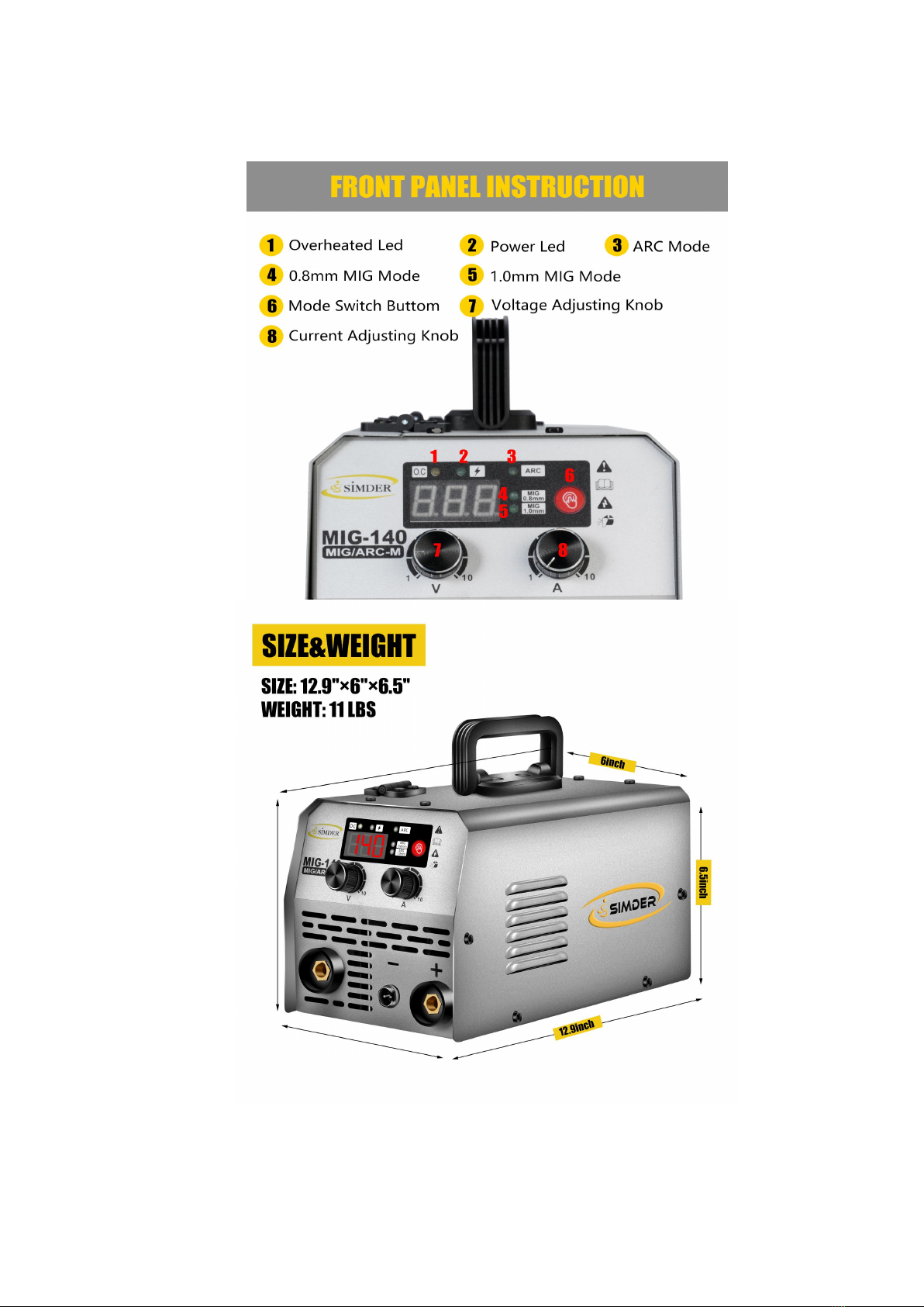
Welder Weight (lbs)
11
11
Welder Size (inches)
12.9*6*6.5
12.9*6*6.5
7
1.4 Overview of machine

www.ssimder.com
8
Unpacking
Check the packaging for any signs of damage.
Carefully remove the machine and retain the packaging until the installation is complete.
Location
The machine should be located in a suitable position and environment. Care should be taken to
avoid moisture, dust, steam, oil or corrosive gases.
Place on a secure level surface and ensure that there is adequate clearance around the machine
to ensure natural airflow.
Input connection
Before connecting the machine you should ensure that the correct power supply is available.
Details of the machine requirements can be found on the data plate of the machine or in the
technical parameters shown in the manual.
The equipment should be connected by a suitably qualified competent person. Always
ensure the ground clamp is properly connected before using.
Never connect the machine to the mains supply if the panels were removed.
Output connections
In general when using ARC welding mode, the electrode holder should be connected the positive
Terminal, the ground clamp to the negative terminal and clamp to the work-piece.
When using MIG welding mode, the ground clamp should be connected to the positive terminal
and and clamp to the work-piece.
2.INSTALLATION

www.ssimder.com
9
MMA Welding
1. Connect the electrode holder to the “-” negative terminal on the left side of the front panel, and
tighten it clockwise;
2. Connect the ground clamp to the “+” positive terminal on the front panel, and tighten it clockwise,
then clamp the ground clamp to the work-piece. As shown in picture;
3. Connect to power, turn on machine, choose ARC Welding Mode.
MIG Welding
1. Install the flux core wire on the spindle adapter, As shown in the picture above. If you need
assist on wire setting, please visit our website: www.ssimder.com for videos or contact us;
2. Connect the ground clamp to the “+” positive terminal on the front panel, and tighten it
clockwise, then clamp the ground clamp to the work-piece;
3. Connect the MIG torch to the “-” negative terminal on the left side, Connect the two-core
control switch to the 2-pin connector in the middle, as shown in the picture
4. Connect to power, turn on machine, choose proper MIG Welding Mode.

www.ssimder.com
10
Before starting any welding activity ensure that you have suitable eye protection and protective
clothing. Also take the necessary steps to protect any persons within the area.
3.1 MMA Welding Mode
After connecting the welding leads as detailed you will need to switch the power switch on the
back panel to “ON”
Select MMA by switching to the MMA welding mode. There is voltage output at both output
terminals. Set the amperage on the machine suitable for the electrode being used. Ensure you
check that you have the electrode polarity correct. Please see below a guide to amperage
required.
Electrode Diameter(mm)
Welding Current(A)
Electrode Diameter(mm)
Welding Current(A)
1.0
20~60
3.2
108~148
1.6
40~84
4.0
140~180
2.0
60~100
5.0
180~220
2.5
80~120
3.2 MIG Welding Mode
Switch the welding mode to 0.8mm flux core or 1.0mm flux core welding mode based on the wire
you were using.
Adjust the “Voltage knob” on the front panel to get proper welding voltage. We will suggest to
start with 50% if you are beginner.
The “Current knob” for wire feeding speed adjusting, we will suggest to start with 30% if you
are beginner. Then Operate the torch trigger, and you can start welding.
Set the welding current after the above preparation. Short circuiting transfer is mainly fit for
electrode wires of diameter flux 0.8/1.0 mm. As a guide for short circuit welding set the welding
current according to the table below.
Wire Diameter(mm)
Welding Current Range(A)
Optimal Current(A)
0.8
50~120
70~100
1.0
70~180
80~120
1.2
80~350
100~200
1) Welding speed selecting
The welding quality and productivity should be taken into consideration for the selecting of welding
speed. In the case that the welding speed increases, it weakens the protection effect and quickens
the cooling. As a consequence, it is not good for weld bead shaping. In the event that the speed is
too slow, the work-piece will be burned through, and a good weld bead will be unavailable. In
practical operation, the welding speed should not exceed 50cm/min.
2) Wire Stick-out
The increase of the stick-out can improve the productivity, but too long stick-out may lead to
excessive spatter, wire breaking and unstable welding. Generally, the stick-out should be 10
times as the welding wire diameter.
3.OPERATION

www.ssimder.com
11
In the event of a failure of the machine, contact an authorized service agent. The following operation
requires sufficient professional knowledge on electric aspects and comprehensive safety
knowledge. Make sure the input cable of the machine is disconnected from the electricity supply
and wait for 5 minutes before removing the machine covers Before taking your unit for servicing,
check the list below.
Symptom Solution
The overheat LED is on.
1. Check the welding current and welding time. Refer to the manual, and operate
according to the specification.
2. Check the running status of the fan when welding. If the fan does not work, and power supply is
normal, check the fan; if the power supply is abnormal, check the connecting cable of the power
supply.
3. Replace the thermal switch if it is damaged or faulty.
The power LED is off, and there is no output current.
1. Check if the fan works. If it does not work, it indicates that the power supply is not present.
Check any fuses cables and supply switches.
2. If the fan works, it indicates that the PCB inside the machine may be defective.
The wire feeder feeds wire when operating the torch trigger,but there is no output current,
and the protection LED is off.
1. Check if the ground clamp is properly connected, or if it is in good condition.(Page 9-10)
2. Check if the quick plug is connected to correct terminal.
3. Check the welding torch for damage.
4.The PCB inside the machine may be defective.
Welding can be carried out when pushing the torch trigger, but the voltage cannot be adjusted.
1. Check if the voltage feedback wire inside the machine is in good condition.
2. PCB inside the machine may be defective.
Welding current is unstable.
1. Check the pressure arm on the wire feeder see if it’s locked properly.
2. Check if the wire feeding wheel matches the wire size(0.8mm-1.0mm)
3. Check the contact tip of the welding torch see if it’s stuck or worn. If so, replace a new one.
4. Check if the welding wire was badly bent or stuck.( cut off the bent wire and reset the wire feeder)
5. Check if the quick plug is loose.
*We highly value our customer’s opinion, If you had any problem using our MIG-140M MIG Welder,
please contact us on Amazon or visit our website.
4.TROUBLE SHOOTING

www.ssimder.com
12
The utilization level of the power source and its working environment should be taken into
consideration in planning the frequency of maintenance of the machine. Appropriate use and
preventive maintenance guarantee the trouble-freest use of the equipment. This allows you to
avoid interruptions in use and increases the productivity of the machine.
5.1 Cables
Check the condition of welding cable and power cord daily. Do not use damaged cables. Also
make sure that all extension cables used in the mains connection are in proper condition and
compliant with regulations.
*NOTE The power cords must be repaired and installed only by electrical contractors and
installers authorized to perform such operations.
5.2 Power source
Before cleaning the interior of the machine, you need to remove the case by unscrewing the
mounting screws at the top and sides of the machine.
*NOTE To prevent damage, wait approximately two minutes after disconnecting the mains cable
before removing the machine’s case. Perform the following cleaning and maintenance at least
every six months:
1. Clean the interior of the machine and the fan grill’s net of any dust and stains – for example,
with a soft brush and vacuum cleaner.
•Do not use pressured air. The stain may become compressed into the grooves of the coolers.
•Do not use a pressure-washing device.
2. Check the electrical connections of the machine. Clean any oxidized connections, and
tighten the loosened ones.
•Check for the right tension before you start repairing the connections.
*NOTE Remember that the machine must be repaired only by an electrical contractor or
installer authorized to perform such operations.
5.3 Regular maintenance
Authorized service agents perform regular maintenance by agreement. Tasks included in regular
maintenance:
•Cleaning of equipment.
•Inspection and maintenance of the welding gun.
•Checking of connectors, switches, and control knobs.
•Checking of electrical connections.
•Checking of the mains cable and plug.
•Replacement of damaged or worn parts.
•Calibration testing, with adjustment of the functions and operational values of the
machine, if necessary.
5.Maintenance
Table of contents
Other Simder Welding System manuals

Popular Welding System manuals by other brands

Lincoln Electric
Lincoln Electric Compact 220 operating manual

Miller
Miller Trailblazer 280 NT owner's manual

MIDWEST FASTENERS
MIDWEST FASTENERS EAGLE Quick start up guide

Puhui
Puhui T-890 user manual

Lincoln Electric
Lincoln Electric NA-5 IM305-C Operator's manual

Lincoln Electric
Lincoln Electric WELDLINE PROTIG III S 10 Instructions for safety, use and maintenance

ABICOR
ABICOR xFUME AF500 operating instructions

Lincoln Electric
Lincoln Electric Eagle 10,000 Plus Operator's manual

Crossfire
Crossfire TRION 250 HD owner's manual

Synergic
Synergic PowerMig Generator 400W Instructions for use

Parkside
Parkside PTMI 180 A1 manual

Lincoln Electric
Lincoln Electric POWERTEC i253C STANDARD Operator's manual


