Sime SHP M ECO 006A Use and care manual
SHP M ECO 006A
SHP M ECO 008A,
SHP M ECO 008 A SL
SHP M ECO 010
SHP M ECO 010T
SHP M ECO 012, SHP M ECO 012 SL
SHP M ECO 012T,
SHP M ECO 012 SL T
SHP M ECO 014
SHP M ECO 014T
SHP M ECO 016, SHP M ECO 016 SL
SHP M ECO 016T,
SHP M ECO 016 SL T
SHP M ECO 018
Chiller and Inverter Air/Water heat pumps with axial fan
User-Installer Manual
Model
Fonderie SIME S.p.A. 7500612 – 05/2022 – R7
-------------------------------------------------------------------------------------------------------------------------------------------------------------------------------
This manual has been created for informative purpose. The company declines any responsibility for the results of any projecting or any installation based on the explanations and/or on the
technical specifications provided in this manual. It is besides forbidden the reproduction under any form of the texts and of the figures contained in this manual.
"This manual is a translation from the official italian language version. For reasons of environmental respect the Company will not provide the hard copy in the original language which could
be directly requested or downloaded from the Company website at any time. In case of any dispute, the original language manual will be the trusted one".

SHP M ECO Air/Water heat pumps with axial fans
2
07 05-2022 Removed size 004 and updated sizes 006A,008A
06 02-2022 Added warnings for users of pacemakers and metal implants, added sound power to
technical data table according to EN 12102:2017, adjusted notes to technical data
table
05 02-2021 Replaced Reg. 2010/30/EU with 2017/1369, updated 4kW size data, modied func-
on diagram legend, modied recommendaons chapter 5.4
04 10-2020 Version SL size 008, 012, 016 kW added, aligned depht dimensions
03 09-2020 Updated images chap. 5.5, added chap. 5.2 and 9.2, updated chap. 5.3, 5.4, 5.7, 5.9,
9, 10, 11.1 (update refrigerante charges and SCOP values for sizes 004, 016, 016T),
13
02 05-2020 Info deleted ch. 5.3, expansion vessel reference deleted ch. 5.6
01 03-2020 Sizes 010T and 012T added, permied use rules added, new specicaons chapter
10.1, additonal info ch. 5.8
00 07-2019 First issue
Rev Date Author Approved Note
Catalogo / Catalogue / Katalog / Catalogue Serie / Series / Serie / Serie / Série
MUI01110L8520-07 AIR-WATER HEAT PUMPS WITH AXIAL FANS

SHP M ECO Air/water inverter heat pumps with axial fans
3
Contents
1. PURPOSE AND CONTENTS OF THE MANUAL 6
1.1 HOW TO KEEP THE MANUAL ...............................................................................................6
1.2 GRAPHIC SYMBOLS USED IN THE MANUAL.......................................................................6
2. NORMATIVE REFERENCES 6
3. PERMITTED USE 7
4. GENERAL SAFETY REGULATIONS 7
4.1 WORKERS' HEALTH AND SAFETY........................................................................................8
4.2 PERSONAL PROTECTIVE EQUIPMENT................................................................................8
4.3 SAFETY SIGNS ......................................................................................................................9
4.4 REFRIGERATN SAFETY DATA SHEET.................................................................................10
4.5 SPECIFIC R32 GAS WARNINGS..........................................................................................11
4.6 R32 GAS CHARGE ...............................................................................................................11
4.7 R32 GAS DISPOSAL.............................................................................................................11
4.8 SAFETY RULES FOR R32 GAS TRANSPORT AND STORAGE.............................................11
5. INSTALLATION 11
5.1 GENERAL ............................................................................................................................11
5.2 TRANSPORT AND STORAGE TEMPERATURE LIMITS.......................................................12
5.3 LIFTING AND HANDLING ...................................................................................................12
5.3.1 Lifting mode............................................................................................................... 12
5.4 POSITIONING AND MINIMUM TECHNICAL CLEARANCES...............................................13
5.5 DIMENSIONS.......................................................................................................................16
5.5.1 Model SHP M ECO 006A / 008A / 008 A SL ............................................................... 16
5.5.2 Model SHP M ECO 010 / 010T / 012 / 012 SL / 012T / 012 SL T ............................... 16
5.5.3 Model SHP M ECO 014 / 014T / 016 / 016 SL / 016T/ 016 SL T / 018 ....................... 17
5.6 ACCESSING THE INNER PARTS.........................................................................................17
5.6.1 Mod. SHP M ECO 006A / 008A / 008 A SL ................................................................. 17
5.6.2 Mod. SHP M ECO 010 / 010T / 012 / 012 SL / 012T / 012 SL T ................................. 18
5.6.3 Mod. SHP M ECO 014 / 014T / 016 / 016 SL / 016T/ 016 SL T / 018 ......................... 18
5.7 PLUMBING CONNECTIONS................................................................................................19
5.7.1 Features of the circuit water ..................................................................................... 19
5.7.2 Typical plumbing diagram......................................................................................... 20
5.7.3 Handbook................................................................................................................... 20
5.7.4 Condensation discharge system............................................................................... 20
5.7.5 Filling the system ...................................................................................................... 20
5.7.6 Discharge of the plant ............................................................................................... 21
5.7.7 Service sleeves........................................................................................................... 21
5.7.8 Air venting valve ......................................................................................................... 21
SHP M ECO Air/Water heat pumps with axial fans
4
5.8 FUNCTIONAL DIAGRAMS...................................................................................................22
5.8.1 SHP M ECO 006A / 008A / 008 A SL .......................................................................... 22
5.8.2 Mod. SHP M ECO 010 / 010T / 012 / 012 SL / 012T / 012 SL T ................................. 23
5.8.3 SHP M ECO 014 / 014T / 016 / 016 SL / 016T/ 016 SL T / 018 .................................. 24
5.9 ELECTRICAL CONNECTIONS .............................................................................................24
5.9.1 Access to the electric panel ...................................................................................... 25
5.9.2 Power supply.............................................................................................................. 25
5.9.3 User terminal block................................................................................................... 26
5.9.4 Control logics............................................................................................................. 27
5.9.5 Fuses.......................................................................................................................... 28
6. STARTUP 28
6.1 SWITCHING ON THE UNIT..................................................................................................28
7. INSTRUCTIONS FOR THE USER 28
8. SHUTDOWNS FOR LONG PERIODS 28
9. MAINTENANCE AND PERIODIC CHECKS 29
9.1 CLEANING THE FINNED COIL ...........................................................................................30
9.1.1 Cleaning the finned coils treated with the anti-corrosion method.......................... 30
9.2 CLEANING OF EXTERNAL SURFACES...............................................................................31
9.3 EXTRAORDINARY MAINTENANCE.....................................................................................31
10.DECOMMISSIONING 31
10.1 RESIDUAL RISKS ..............................................................................................................31
11.TECHNICAL DATA 36
11.1 STANDARD UNIT TECHNICAL SHEET..............................................................................36
11.2 SILENCED VERSION UNIT TECHNICAL SHEET...............................................................40
11.3 UNIT AND AUXILIARY ELECTRICAL DATA .......................................................................41
12.OPERATING LIMITS 41
12.1 EVAPORATOR WATER FLOW RATE...................................................................................41
12.2 COOLING WATER PRODUCTION SUMMER MODE ........................................................41
12.3 HEATING WATER PRODUCTION WINTER MODE...........................................................41
12.4 AMBIENT AIR TEMPERATURE AND SUMMERISED TABLE ............................................42
13.USER INTERFACE - CONTROLLER 44
13.1 MENU ................................................................................................................................45
13.2 MENÙ SETPOINT ..............................................................................................................45
13.3 ALARMS MENU ERR.......................................................................................................45

SHP M ECO Air/water inverter heat pumps with axial fans
5
The manual of the SHP M ECO units, contains all the necessary informaon for opmal use of the equipment under safe condions for the
operator.
1. PURPOSE AND CONTENTS OF THE MANUAL
This manual provides basic informaon as to the selecon, installaon, operaon and maintenance of the SHP M ECO unit. It is intended for
the operators of the appliance and it enables them to use the equipment eciently, even if they do not have any previous specic knowledge.
-
-
The manual describes the machine at the moment it was sold. It must therefore be considered adequate with respect to the state-of-the-art in
terms of potenality, ergonomics, safety and funconality.
The company also performs technological upgrades and does not consider itself obliged to update the manuals of previous machine versions
which could even be incompable. Therefore make sure to use the supplied manual for the installed unit.
It is recommended to follow the instrucons contained in this manual, especially those concerning safety and roune maintenance.
HOW TO KEEP THE MANUAL
The manual has to always be kept together with the unit it refers to. It has to be stored in a safe place, away from dust and moisture It must be
accessible to the operator all users who must consult it if there is any doubt about the use of the machine.
The company reserves the right to modify its products and related manuals without necessarily updang previous versions of the reference
material. We also decline any responsibility for possible inaccuracies in the manual if due to prinng or transcripon errors.
Any updates that are sent to the customer must be kept as an annex to this manual.
The company is available to give any detailed informaon about this manual and to give informaon regarding the use and the maintenance of
its own units.
GRAPHIC SYMBOLS USED IN THE MANUAL
2. NORMATIVE REFERENCES
The units SHP M ECO are designed in accordance with the following direcves and harmonized standards on the safety of machinery:
• Community direcves, 2014/35/UE, 2014/30/UE, 2011/65/UE, 2012/19/UE, 2014/68/UE
• Norms UNI EN 12735-1
• Norm CEI EN 60335-1, CEI EN 60335-2-40
• Norms CEI EN 55014-1, CEI EN 55014-2
• EN 50581
• EN 14276
And the following direcves, regulaons and standards on ecodesign and energy labelling:
• Community direcve 2009/125/CE e subsequent transposion
• Community direcve 2010/30/EU and subsequent transposal
• EU Regulaon 811/2013
• EU Regulaon 813/2013
• EN 14511-1:2018, EN 14511-2:2018, EN 14511-3:2018, EN 14511-4:2018
• EN 14825:2018

SHP M ECO Air/Water heat pumps with axial fans
6
3. PERMITTED USE
• The company excludes any contractual and extra contractual liability for damage caused to persons, animals or objects, by incorrect instal-
laon, seng and maintenance, improper use of the equipment, and the paral or supercial reading of the informaon contained in this
manual.
• These units are built for the heang and/or cooling of water. Any other use not expressly authorised by the manufacturer is considered
improper and therefore not allowed. The uid to be used is exclusively water or a mixture of water and glycol in case of low water tem-
peratures.
• The installaon place and the water and electric circuit must be established by the plant designer and must take into account both technical
requirements as well as any applicable local laws and specic authorisaons.
• All work must be carried out by experienced and qualied personnel, competent on the exisng regulaons in country where the installa-
on takes place.
• This appliance is intended to be used by expert or trained operators in shops, light industry and in factories, or for commercial use by
non-expert personnel.
• The appliance may be used by children at least 8 years old and by persons with reduced physical, sensory or mental capabilies or without
experience or the necessary knowledge as long as they are supervised or aer they themselves have received instrucons on the safe use
of the appliance and understand the relevant dangers. Children must not play with the appliance. The cleaning and maintenance which the
user is expected to carry out on the unit cannot be done by children without supervision.
• Direct interacon with the unit by persons with electrically controlled medical devices, such as pacemakers, is prohibited, as harmful inter-
ference may result. It is recommended that an adequate distance be maintained from the installaon site of the unit, as indicated by the
medical system used.
4. GENERAL SAFETY REGULATIONS
Before starng any type of operaon on the units, every operator must be perfectly familiar with the operaon of the machine and its controls
must have read and understood all the informaon in this manual.

SHP M ECO Air/water inverter heat pumps with axial fans
7
-
WORKERS' HEALTH AND SAFETY
The European Union has issued some direcves concerning the safety and health of workers, including: 89/391/EEC, 89/686/EEC, 2009/104/EC,
86/188/EEC and 77/576/EEC and subsequent amendments which every employer is obliged to follow and have followed. We observe therefore
that:
-
The unit works with R32 refrigerant, which is included in the list of greenhouse gases (GWP 675) which are subject to the requirements in EU
regulaon n. 517/2014 called “F-GAS” (mandatory in the European zone). Among the provisions of this regulaon, imposes on operators working
in installaons operang with greenhouse gases to hold a cercate, issued or recognised by the competent authority, cerfying that they have
passed an examinaon authorising them to carry out such work. In parcular
• Up to 3kg total refrigerant in the appliance: category 2 cercaon.
• 3 kg and more total refrigerant in the appliance: category 1 cercaon.
The gaseous form of R32 refrigerant is heavier than air and if released into the environment, most of it tends to concentrate in poorly venlated
areas. Inhaling it can cause dizziness and sensaons of suocaon and can develop lethal gas if in contact with naked ames or hot objects (see
the refrigerant’s safety data sheet).
Pay aenon to the fact that refrigerant uids can be odourless.
For any operaon on the heat pump system:

SHP M ECO Air/Water heat pumps with axial fans
8
PERSONAL PROTECTIVE EQUIPMENT
Personal protecve equipment must be used when operang and mainteining the units, such as:
-
soles.
-
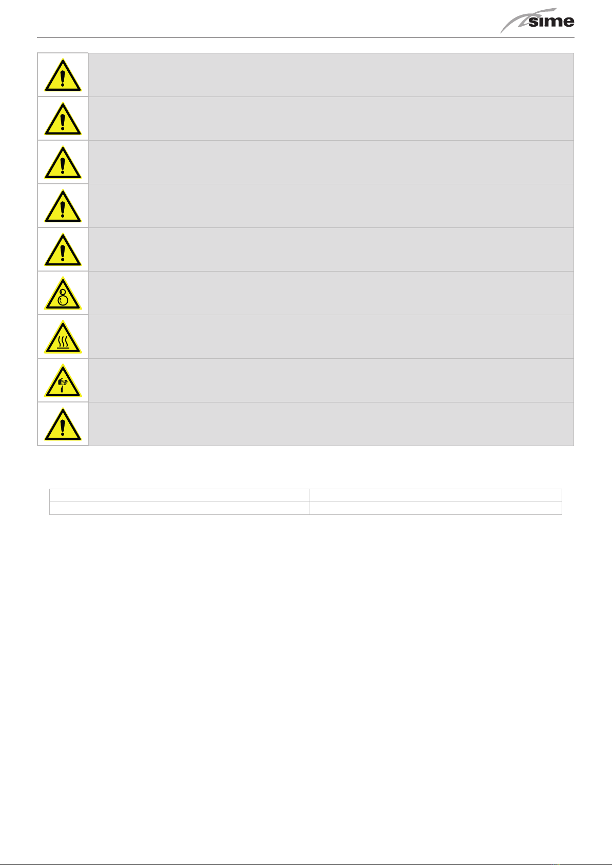
SAFETY SIGNS
The unit features the following safety signs, which must be complied with:
Moving parts
SHP M ECO Air/water inverter heat pumps with axial fans
9
REFRIGERATN SAFETY DATA SHEET
Name: R32
HAZARDS IDENTIFICATION
Main hazards:
Specifi c hazards:
FIRST AID MEASURES
General informa� on:
Inhala� on:
Eye contact:
Skin contact:
FIRE FIGHTING MEASURES
Ex� nguishing media:
Specifi c hazards:
Specifi c methods:
ACCIDENTAL RELEASE MEASURES
Personal precau� ons:
Environmental precau� ons:
Cleaning methods:
HANDLING AND STORAGE
Handling:
technical measures/precau� ons:
Advice for safe use:
Storage:
EXPOSURE CONTROLS/PERSONAL PROTECTION
Control parameters:
Respiratory protec� on:
Eye protec� on:
Hand protec� on:
Hygienic measures:
PHYSICAL AND CHIMICAL PROPERTIES
Colour:
Odour:
Boiling point:
Flash point:
Rela� ve gas density (air=1)
Rela� ve liquid density (water=1)
Solubility in water:
STABILITY AND REACTIVITY
Stability:
Materials to avoid:
Decomposi� on products
hazardous:
TOXICOLOGICAL INFORMATION
Acute toxicity:
Local eff ects:
Long term toxicity:
ENVIRONMENTAL INFORMATION
Global warming poten� al
GWP (R744=1):
Ozone Deple� on Poten� al ODP
(R11=1):
Disposal considera� on:

SHP M ECO Air/Water heat pumps with axial fans
10
SPECIFIC R32 GAS WARNINGS
The R32 refrigerant gas:
• is odourless;
• is ammable, but only if there are naked ames;
• it may cause an explosion, but only if a given concentraon in air is reached.
It is good pracce to follow these guidelines:
• do not smoke near the unit;
• ax a no smoking sign near the unit;
• keep the room where the unit is installed well venlated;
• do not drill or burn the unit;
• do not place the unit near sources of ignion, such as open ames, electric heaters, etc;
• every extraordinary maintenance or repair on the unit must be performed by skilled technicians or qualied personnel;
• a gas leak test must be performed aer installaon.
R32 GAS CHARGE
• ensure the R32 is not contaminated by any other types of refrigerant;
• keep the gas cylinder in an upright posion when charging;
• apply the appropriate label on the unit aer charging;
• do not charge more refrigerant gas than needed;
• when charging is completed, perform leak tests before the operang test;
• once all the above operaons have been completed, a second leak test should be performed.
R32 GAS DISPOSAL
• Do not discharge the gas in area where there is a risk of explosive mixtures forming with air. The gas should be disposed of in a suitable are
with ashback arrestor. Contact the supplier if operang instrucons are considered necessary.
SAFETY RULES FOR R32 GAS TRANSPORT AND STORAGE
Before opening the unit’s packaging, ensure there are no gas leaks in the environment with an appropriate gas detector. Check that there are
no ignion sources near the unit.
No smoking near the unit.
Transport and storage must be performed in accordance with the naonal regulaons in force. Specically, according to ADR provisions, the total
maximum quanty by transport unit in terms of net mass for ammable gases is 333 kg.
5. INSTALLATION
GENERAL
When installing or intervening on the chiller unit, it is necessary to strictly follow the rules listed in this manual, to observe all the indicaons on
the unit and however to take all possible precauons. Failure to comply with the rules reported on this manual can create dangerous situaons.
The company must be informed, within 8 days, of the extent of the damage. The Customer should prepare a wrien statement of any severe
damage.
SHP M ECO Air/water inverter heat pumps with axial fans
11
TRANSPORT AND STORAGE TEMPERATURE LIMITS
Minimum storage temperature [°C] -10°C
Maximum storage temperature [°C] +50°C
LIFTING AND HANDLING
The handling must be performed by qualied personnel, properly equipped with appropriate tools to the weight and the encumbrance of the
unit, in compliance with safety regulaons of accident prevenng
It is recommended:
1. check the weight on unit technical label or on table of technical data;
2. check moving the unit there are no disconnected paths, ramps, steps, doors that could aect the movement and damage the unit;
3. check that the unit remains horizontal when moving;
4. before moving the unit check the devices are suitable for liing and preserving unit integrity;
5. perform liing only by one of the listed procedures;
6. Before starng handling make sure, the unit is in stable equilibrium.

SHP M ECO Air/Water heat pumps with axial fans
12
Following liing modes are allowed:
• forkli truck
• ropes/ chains + sling bar
Make sure to tension the liing ropes gradually and check their correct posioning.
Liing through forkli truck
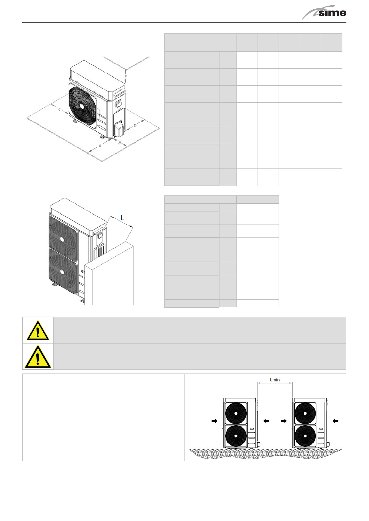
POSITIONING AND MINIMUM TECHNICAL CLEARANCES
All models are designed and constructed for outdoor installaons.
It is advisable to create an adequately sized support base for the unit. The units transmit a small amount of vibraons to the ground: however,
it is advisable to place an-vibraon mounts between the base frame and the supporng surface.
It is very important to avoid recirculaon between intake and delivery air, so as not to downgrade performance of the unit or even to interrupt
its normal operaon.
This is why the Minimum clearances shown below must be strictly guaranteed.
SHP M ECO Air/water inverter heat pumps with axial fans
13
Model A B C D E
SHP M ECO 006A mm 1500 500 400 400 500
SHP M ECO 008 A SL mm 1500 500 400 400 500
SHP M ECO 010/
SHP M ECO 010T mm 1500 500 400 400 500
SHP M ECO 012 SL/
SHP M ECO 012 SL T
mm 1500 500 400 400 500
SHP M ECO 014/
SHP M ECO 014T mm 1500 500 400 400 500
SHP M ECO 016 SL/
SHP M ECO 016 SL T
mm 1500 500 400 400 500
SHP M ECO 018 mm 1500 500 400 400 500
Model L
SHP M ECO 006A mm 500
SHP M ECO 008 A SL mm 500
SHP M ECO 010/
SHP M ECO 010T mm 500
SHP M ECO 012 SL/
SHP M ECO 012 SL T
mm 500
SHP M ECO 014/
SHP M ECO 014T mm 500
SHP M ECO 016 SL/
SHP M ECO 016 SL T
mm 500
SHP M ECO 018 mm 500
In the event of side-by-side units, the minimum Lmin distance be-
tween them is 1 m.
SHP M ECO Air/Water heat pumps with axial fans
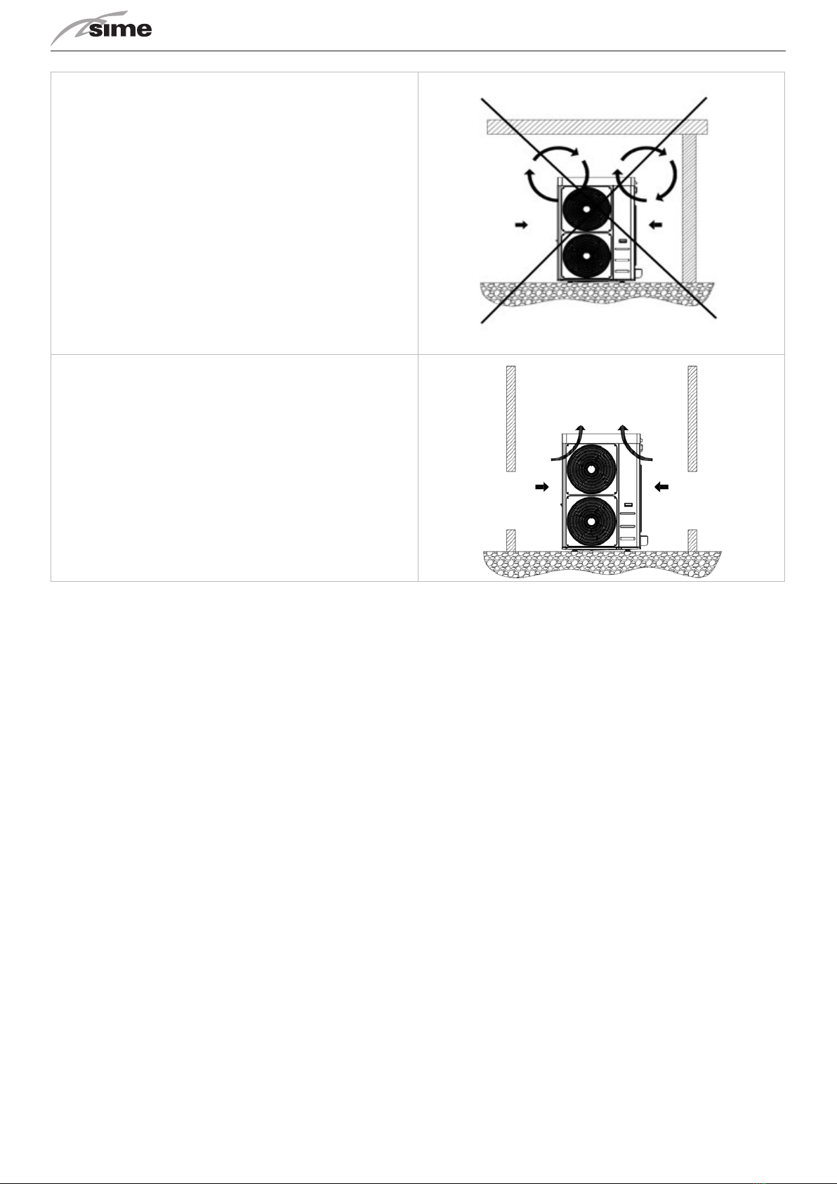
14
Covering with canopies or placing near plants or walls should be avoid-
ed to prevent air recirculaon.
In the event of winds stronger than 2.2 m/s the use of wind barriers is
recommended.
It is recommended to make an environmental impact valutaon according to the power and sound pressure data reported in the technical data
chapter and the sound emission limits according to the installaon area of the unit, with reference to the DPCM of 14/11/1997. An assessment
must also be made if the unit is installed in the vicinity of workers, according to il D. LGS. 81/2008 Art. 189 and following.
In order to reduce vibraons and noise, we recommend the use of rubber seals for wall installaon.

SHP M ECO Air/water inverter heat pumps with axial fans
15
DIMENSIONS
Model SHP M ECO 006A / 008A /008 A SL
IN/OUT: 1"M G
E: Power supply input
E
IN
OUT
830
120 657 140
354
104 63
226 95
394
918
E
Model SHP M ECO 010 / 010T / 012 / 012 SL / 012T / 012 SL T
IN/OUT: 1"M G
E: power supply input
1047
134 673 134
403
87
936
109
174
455
311 144
E E
OUT
IN
SHP M ECO Air/Water heat pumps with axial fans
16
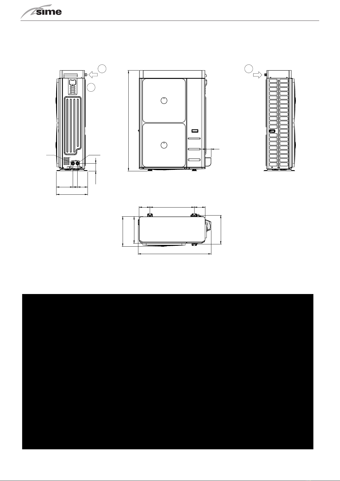
Model SHP M ECO 014 / 014T / 016 / 016 SL / 016T/ 016 SL T / 018
IN/OUT: 1”M G
E: power supply input
73
1409
237 66145
448
106
1044
155634156
404
376
418
E
A
E
IN
OUT
ACCESSING THE INNER PARTS
Mod. SHP M ECO 006A / 008A / 008 A SL

SHP M ECO Air/water inverter heat pumps with axial fans
17
1. Remove the cover
2. Uscrew the screws (number 2; 3; 4) of the sheet metal cover of the user interface and the screw (number 1) of the side panel to separate
the front sheet metal from the side panel (Detail A).
3. Unscrew in sequence the screws (number 5; 6;7) in order to move the front panel slightly forward and to be able to reach the screw (num-
ber 8) visible in detail B.
4. Uncrew the screws (number 8; 9 visible in detail B) and those on the coil side of the unit. To remove the side panel, pull it upwards (to free
the tab at the base) and remove it.
Mod. SHP M ECO 010 / 010T / 012 / 012 SL / 012T /012 SL T
1. Remove the cover by undoing the screws (number 1; 2; 3; 4; 5; 6; 7; 8).
2. Undo the screws (number 9; 10) of the front sheet and then push the panel downwards to remove the tabs (Detail A); pull the panel for-
ward to remove it.
3. Undo the screws (number 11; 12;13) and those on the coil side of the unit. To remove the side panel, pull it upwards (to free the tab at
the base) and remove it
Mod. SHP M ECO 014 / 014T / 016 / 016 SL / 016T /016 SL T / 018
1. Remove the cover by undoing the screws (number 1; 2; 3; 4; 5; 6; 7; 8;9).
2. Undo the screws (number 10; 11) of the front sheet and then push the panel downwards to remove the tabs (Detail A); pull the panel
forward to remove it.
3. Undo the screw (number 12) and those on the coil side of the unit. To remove the side panel, pull it upwards (to free the tab at the base)
and remove it.

SHP M ECO Air/Water heat pumps with axial fans
18
PLUMBING CONNECTIONS
The plumbing connecons must be made in accordance with naonal and/or local regulaons; pipes can be made of steel, galvanised steel or
PVC. Pipes must be accurately sized according to the nominal water ow rate of the unit and the pressure drops of the water circuit. All pipes
must be insulated with closed-cell material of adequate thickness. The chiller must be connected to the pipes using new exible joints, not re-
used ones. The water circuit should include the following components:
• Well thermometers to monitor the circuit’s temperature.
• Manual gate valves to isolate the chiller from the water circuit.
• Metal Y lter and dirt separator (installed on the return pipe) with metal mesh no larger than 1 mm.
• Loading group and exhaust valve where necessary.
-
To guaratee correct operaon of the unit, the water must be appropriately ltered (see the instrucons at the start of this paragraph) and there
must be only a minimum amount of dissolved substances. The maximum allowed values are shown below
MAXIMUM CHEMICAL-PHYSICAL PROPERTIES ALLOWED FOR THE CIRCUIT WATER
PH 7,5 - 9
Electrical conducvity 100 - 500 μS/cm
Total hardness 4,5 – 8,5 dH
Temperature ˂ 65°C
Oxygen content ˂ 0,1 ppm
Max glycol quanty 40 %
Phosphates (PO4) ˂ 2ppm
Manganese (Mn) < 0,05 ppm
Iron (Fe) < 0,3 ppm
Alkalinity (HCO3) 70 – 300 ppm
Chloride ions (Cl-) < 50 ppm
Sulphate ions (SO4) < 50 ppm
Sulphide ions (S) No one
Ammonium ions (NH4) No one
Silica (SiO2) < 30 ppm

SHP M ECO Air/water inverter heat pumps with axial fans
19
A recommended connecon diagram is shown bellow.
T
T
P
Glycol fill
T
M
T
secondary pump
M
to radiant panel
to fancoil
from fancoil
S
A
B
AB
to sanitary users
from water supply
Sanitary
probe
Remote plant
probe
Handbook
If you need more informaon about the possible conguraons, there is a handbook which is a technical notebook including a series of system
diagrams that have been highlighted regarding the installaon conguraon of our high eciency heat pumps. The Handbook is also intended
to show the symbiosis potenal with some of our elements found in the catalogue.
Consult the technical notebook at our headquarters.
All units are built in such a way that the base of the unit acts as a condensate drip tray. A plasc ng is standard supplied to be connected below
the base in the specic slot in order to connect a pipe which channels the condensate.
Hole in bottom panel of
outdoor unit
Gasket
Drain tting
Gasket
Each unit is therefore ed with a hole on the base of the hydronic kit (on the coil side) to drain condensaon which could drip from the pipes
of the plumbing system. Since these pipes are well insulated, a minimum amount of condensaon is produced anyway and therefore it is not
mandatory to connect a drain pipe to this ng.
UNDER THE UNIT WITHOUT DAMAGING IT BY FREEZING.
SHP M ECO Air/Water heat pumps with axial fans
20
If the unit needs to be drained completely, rst close the manual inlet and outlet gate valves (not included in supply) and then detach the pipes
on the outside of the water inlet and outlet to drain liquid from the unit (to make this operaon easier, it is recommended to install two drain
valves between the unit and manual gate valves on the outside of the water inlet and outlet).
B
A
If it is necessary to top up the system or adjust the glycol content, the service tap can be used.
Unscrew the cap of the service tap (A) and connect a pipe of 14 or 12 mm (ineral diameter
measurements - check the tap model installed on your unit) connected to the water mains to
the hose connector, then ll the system by unscrewing the ring nut (B). Once the operaon is
completed, ghten the ring nut (B) again and screw the cap (A). In any case, it is advisable to
use an external tap to ll the system.
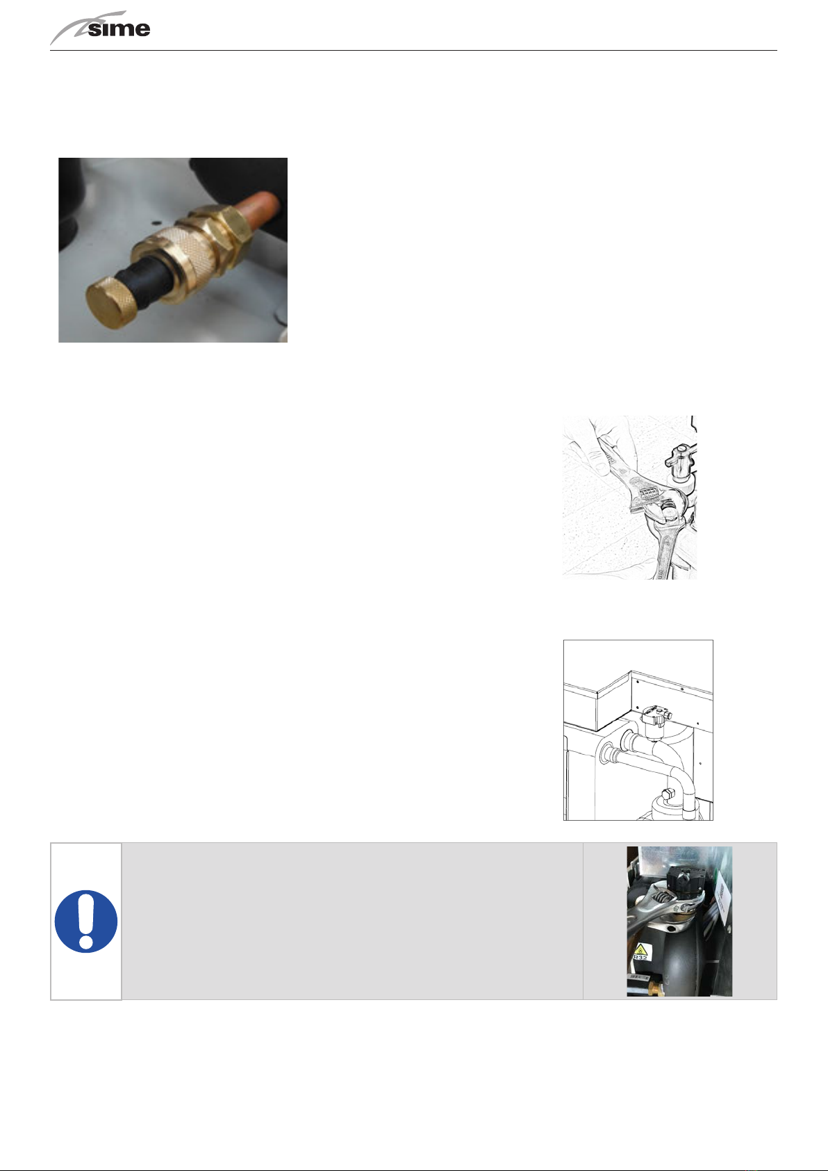
In the hydraulic circuit of the unit, 2 service sleeves with gap (1/4”G) are installed
dowstream and upstream of the circulator (ref. SM unit funconal diagram paragraph
5.8.2, 5.8.3 and 5.8.4); when removing/mounng the cap, use 2 spanners as shown in
the gure to avoid damaging the pipes.
The unit is ed with an air venng valve to automacally remove air that has built up in
the circuit, prevenng undesirable eects such as premature corrosion and wear, lower
performance and low exchange output.
The device has also a safety funcon in that, in the event of exchanger breakdown, it
allows the refrigerant gas to escape into the outside air, prevenng it from being trans-
ported to the internal terminals.
The valve can be kept in a closed posion by closing the plug on the drain; by loosening
the plug, the valve remains in open posion and air is vented automacally.
This manual suits for next models
15
Table of contents
Other Sime Chiller manuals

Popular Chiller manuals by other brands


Halsey Taylor
Halsey Taylor SJ8GRN Installation, Care and Use Manual

Trane Technologies
Trane Technologies RTAG 225 Installation operation & maintenance

Liebert
Liebert HPC-S 022 Product documentation

Trane
Trane Airfinity XL IC140 manual

AIREDALE
AIREDALE LogiCool InRak Technical manual

Carrier
Carrier AQUAFORCE 30XA080-500 installation instructions


