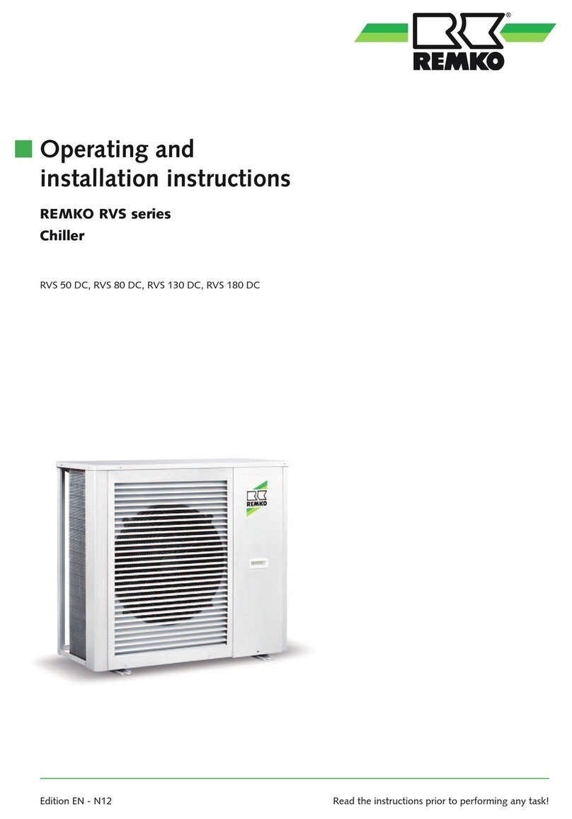
Sime SHP M ECO 006A KA User manual

SHP M ECO 006A KA
SHP M ECO 008A KA,
SHP M ECO 008 A SL KA
SHP M ECO 010 KA
SHP M ECO 010KA T
SHP M ECO 012 KA,
SHP M ECO 012 SL KA
SHP M ECO 012KA T,
SHP M ECO 012 SL KA T
SHP M ECO 014KA
SHP M ECO 014KA T
SHP M ECO 016KA,
SHP M ECO 016 SL KA
SHP M ECO 016KA T,
SHP M ECO 016SL KA T
SHP M ECO 018KA
Chiller and Inverter Air/Water heat pumps with axial fans
Controller Manual
Model
Fonderie SIME S.p.A. 7500616 – 05/2022 – R7
-------------------------------------------------------------------------------------------------------------------------------------------------------------------------------
This manual has been created for informative purpose. The company declines any responsibility for the results of any projecting or any installation based on the explanations and/or on the
technical specifications provided in this manual. It is besides forbidden the reproduction under any form of the texts and of the figures contained in this manual.
"This manual is a translation from the official italian language version. For reasons of environmental respect the Company will not provide the hard copy in the original language which could
be directly requested or downloaded from the Company website at any time. In case of any dispute, the original language manual will be the trusted one".

SHP M ECO Heat pumps inverter air/water with axial fans
2
07 05-2022 E.G. A.B. 06A, 08A sizes update, GI chapter eliminaon
06 12-2021 M.S. A.B. Eliminaon cap. 9.1
05 03-2021 A.B. A.B. Update cap. 8-9.1-10.15-10.16-10.17-14.3
04 09-2020 M.S. A.B. Compressor shutdown acvaon logic update
03 06-2020 M.S. A.B. Adding owmeter chapter
02 03-2020 M.S./K.G. A.B. Modicaon of the chapters 6, 9,11, 12 and 15
01 10-2019 M.S. A.B. Updang
Rev Data Approvato
Catalogo / Catalogue / Katalog / Catalogue Serie / Series / Serie / Serie / Série
MCO0110L8500-07 CONTROLLER FOR AIR/WATER INVERTER-CONTROLLED CHILLERS AND HEAT PUMPS
WITH AXIAL FANS
The electrical and electronic products and any waste should not be disposed of with normal household waste, but disposed of
according to WEEE law in accordance with the direcve 2012/19/EU, inquiring thereof at the place of residence or with the retailer
in the case where the product is replaced with a similar one.

3
SHP M ECO Heat pumps inverter air/water with axial fans
Contents
1.HOW TO KEEP THE MANUAL 6
1.1 GRAPHIC SYMBOLS USED IN THE MANUAL.......................................................................6
2.PERMITTED USED 6
3.GENERAL SAFETY GUIDELINES 6
3.1 PERSONAL PROTECTIVE EQUIPMENT................................................................................6
3.2 WORKERS' HEALTH AND SAFETY........................................................................................6
4.PURPOSE AND CONTENTS OF THE MANUAL 8
5.USER INTERFACE - CONTROLLER 9
5.1 MENU ....................................................................................................................................9
5.2 SETPOINT MENU ..................................................................................................................9
5.3 PASSWORD MENU PSS....................................................................................................10
5.4 PROBES MENU TP ...........................................................................................................10
5.5 ALARMS MENU ERR ........................................................................................................10
5.6 DIGITAL INPUTS MENU ID ...............................................................................................10
5.7 PARAMETERS MENU PAR................................................................................................10
5.8 OPERATING HOURS MENU OHR .....................................................................................11
5.9 MENU VERSIONE FIRMWARE FIR...................................................................................11
5.10 LOG MENU HIST .............................................................................................................11
5.11 USB MENU USB..............................................................................................................11
5.11.1 Firmware update [updf]........................................................................................... 11
5.11.2 Parameters update [uppa] ...................................................................................... 11
5.12 DISPLAY.............................................................................................................................11
5.12.1 Led............................................................................................................................ 12
5.13 TERMINAL BLOCK ............................................................................................................12
6.EDITING DYNAMIC SET-POINT 13
6.1 SETTINGS FOR STANDARD CLIMATIC CURVES................................................................13
6.2 EDIT THE SETPOINT FROM 010V INPUT OR FROM RATIOMETRIC INPUT ...................14
7.CIRCULATOR 14
7.1 CONTINUOUS OPERATION P03=0 DEFAULT ................................................................15
7.2 OPERATION ON CALL BY TEMPERATURE CONTROLLER P03=1...................................15
7.3 OPERATING ON CALL BY TEMPERATURE CONTROLLER WITH PERIODIC ACTIVATION15
7.4 OPERATION WITH HEATER ACTIVE ...................................................................................15
7.5 PROPORTIONAL REGULATION OF THE CIRCULATOR......................................................15
7.6 SYSTEM VENTING...............................................................................................................16
8.COMPRESSOR OR ACTIVATION LOGIC 16
8.1 REGULATION IN COOLING MODE ......................................................................................16
8.2 REGULATION IN HEAT MODE.............................................................................................16

SHP M ECO Heat pumps inverter air/water with axial fans
4
9.DISSIPATION FAN CONTROL 17
10.CONTROLLER FUNCTIONS 17
10.1 ANTIFREEZE PROTECTION HEATERS IF KA ACCESSORY IS AVAILABLE....................17
10.2 ENABLING DOMESTIC HOT WATER PRODUCTION.........................................................17
10.2.1 Memorising the probe in heating mode.................................................................. 18
10.2.2 Heating mode on dhw storage tank........................................................................ 18
10.2.3 Insufficient heat exchange in a dhw system........................................................... 18
10.3 REMOTECONTROLLED FUNCTIONS..............................................................................18
10.3.1 On/off........................................................................................................................ 18
10.3.2 Summer/winter mode change ................................................................................ 18
10.3.3 Dhw enable from digital input................................................................................. 18
10.4 SYSTEM WATER REMOTE PROBE....................................................................................19
10.5 AUXILIARY HEATERS ........................................................................................................19
10.5.1 Plant heater ............................................................................................................. 19
10.5.2 Plant heater in defrost............................................................................................. 19
10.5.3 Dhw heater............................................................................................................... 19
10.5.4 Single plant/dhw integration heater ....................................................................... 20
10.6 INTEGRATION HEATER SELECTION MODE .....................................................................20
10.7 CIRCULATOR MANAGEMENT WITH HEATER ON ............................................................20
10.8 BOILER ENABLING...........................................................................................................20
10.9 ACTIVATION OF INTEGRATION HEATERS AND BOILER IN JOINT OPERATION AND
IN SUBSTITUTION OF HEAT PUMP COMPRESSOR ..........................................................20
10.9.1 Operation in heat pump mode ................................................................................ 21
10.9.2 Joint operation (i bracket) ....................................................................................... 21
10.9.3 Joint operation (ii bracket) ...................................................................................... 21
10.9.4 Operation in substitution......................................................................................... 21
10.10 OPERATING BRACKETS ACTIVATION OF INTEGRATION HEATERS PLANT RE
MOTE WATER PROBE NOT ENABLED ..............................................................................21
10.10.1 Auxiliary systems offset management.................................................................. 24
10.11 WARNINGS......................................................................................................................25
10.11.1 Plant season .......................................................................................................... 25
10.11.2 Alarm...................................................................................................................... 25
10.11.3 Machine block........................................................................................................ 25
10.11.4 Defrost.................................................................................................................... 25
10.12 DEFROST CYCLE.............................................................................................................25
10.13 COMPRESSOR CRANKCASE HEATER............................................................................25
10.14 DOUBLE SETPOINT.......................................................................................................25
10.15 MINIMUM HZ FUNCTIONALITY ......................................................................................25
10.16 MAXIMUM HZ FUNCTIONALITY......................................................................................26
10.17 FLOWMETER ...................................................................................................................26

5
SHP M ECO Heat pumps inverter air/water with axial fans
11.FUNCTIONS THAT CAN BE ACTIVATED WITH HI-T2 ACCESSORY (OPTIONAL) 26
12.FUNCTIONS THAT CAN BE ACTIVATED WITH GI MODULE (OPTIONAL) 27
13.TABLES OF PERMITTED SETUPS FOR USER AND INSTALLER 27
14.ALARMS 30
14.1 E006 FLOW SWITCH .......................................................................................................31
14.2 E018 HIGHTEMPERATURE ...........................................................................................31
14.3 E020 INVERTER TRASDUCTORS....................................................................................31
14.4 E005 ANTIFREEZE..........................................................................................................31
14.5 E611÷E681 PROBE ALARMS ..........................................................................................31
14.6 E801 TIMEOUT INVERTER..............................................................................................31
14.7 E851 ÷E971 INVERTER ...................................................................................................31
14.8 E00 REMOTE ON/OFF WARNING.................................................................................31
14.9 E001 HIGHPRESSURE...................................................................................................31
14.10 E002 LOWPRESSURE..................................................................................................31
14.11 E008 DRIVER LIMITATION ............................................................................................31
14.12 E041 4WAY VALVE........................................................................................................31
14.13 POWER FAILURE.............................................................................................................32
14.14 UTILITIES BLOCK ALARM TABLE...................................................................................32
15.MODBUS VARIABLES 32

SHP M ECO Heat pumps inverter air/water with axial fans
6
1. HOW TO KEEP THE MANUAL
The manual has to always be kept together with the unit it refers to. It has to be stored in a safe place, away from dust and moisture. It must be
accessible to all users who shall consult it any me they are in doubt on how to operate the equipment.
The company reserves the right to modify its products and related manuals without necessarily updang previous versions of the reference
material. We also decline any responsibility for possible inaccuracies in the manual if due to prinng or transcripon errors.
The customer shall store any updated copy of the manual or parts of it delivered by the manufacturer as an aachment to this manual.
The company is available to give any detailed informaon about this manual and to give informaon regarding the use and the maintenance of
its own units.
GRAPHIC SYMBOLS USED IN THE MANUAL
2. PERMITTED USED
• The company excludes any contractual and extra contractual liability for damage caused to persons, animals or objects, by incorrect instal-
laon, seng and maintenance, improper use of the equipment, and the paral or supercial reading of the informaon contained in this
manual.
• These units are built for the heang and/or cooling of water. Any other use not expressly authorised by the manufacturer is considered
improper and therefore not allowed.
• All the work must be executed by skilled and qualied personnel, competent on the exisng regulaons in country of installaon.
• This appliance is intended to be used by expert or trained operators in shops, light industry and in factories, or for commercial use by
non-expert personnel.
• The appliance may be used by children at least 8 years old and by persons with reduced physical, sensory or mental capabilies or without
experience or the necessary knowledge as long as they are supervised or aer they themselves have received instrucons on the safe use
of the appliance and understand the relevant dangers. Children must not play with the appliance. The cleaning and maintenance which the
user is expected to carry out on the unit cannot be done by children without supervision.
3. GENERAL SAFETY GUIDELINES
Before starng any type of operaon on the unit, every user and operator must have perfect knowledge of operaon of the machine and of its
controls and have read and understood all of the informaon in this manual and in the user-installer manual.
PERSONAL PROTECTIVE EQUIPMENT
Refer to the user-installer manual which accompanies the unit.
WORKERS' HEALTH AND SAFETY
Refer to the user-installer manual which accompanies the unit.

7
SHP M ECO Heat pumps inverter air/water with axial fans
IT IS PROHIBITED:
For unauthorised personnel to access the electric panel.
CAUTION:
-

SHP M ECO Heat pumps inverter air/water with axial fans
8
-
Connect the conductors in order: phase, neutral and earth.
4. PURPOSE AND CONTENTS OF THE MANUAL
The manual is intended to provide the essenal informaon to congure the controller of the units.
It is addressed to the installer and operators of the appliance and it enables them to use the equipment eciently, even if they do not have any
previous specic knowledge of it.
Not all of the funcons described can be acvated and/or selected at the same me. Contact our headquarters for further informaon.
The manual describes the machine at the moment it was sold. It must therefore be considered adequate with respect to the state-of-the-art in
terms of potenality, ergonomics, safety and funconality.
The company also performs technological upgrades and does not consider itself obliged to update the manuals of previous machine versions
which could even be incompable. Therefore make sure to use the supplied manual for the installed unit. Contact our headquarters in case of
updates or doubts.
The user is recommended to follow the instrucons contained in this booklet, especially those concerning safety and roune maintenance.

9
SHP M ECO Heat pumps inverter air/water with axial fans
5.
Select the operang mode and manually reset any alarms.
Each me you press the key you have the following sequence:
OFF -> COOL -> HEAT -> OFF
If DHW is enabled, the sequence is the following:
OFF -> COOL -> COOL+SAN -> HEAT -> HEAT+SAN -> OFF
While seng the parameters, this key has the funcon of sending BACK by one level.
Grants access to the parameter seng menu and allows you to set the summer, winter and sanitary setpoint.
UP key. In the parameter seng mode, it allows you to move to a higher menu or to increase the parameter value when in “edit”
mode.
DOWN key. In the parameter seng mode, it allows you to move to a lower menu or to decrease the parameter value when in
“edit” mode.
MENU
The following are the main features for navigang the menus, especially describing funcons which are not obvious. The main menu has the
following items:
MENU LABEL PASSWORD LEVEL OTHER CONDITIONS
Setpoint Set User Not accessible if connected to Hi-T2
Probes tP Installer ---
Alarms Err User Only if acve alarms
Digital input Id Installer ---
Parameters Par Installer ---
Password PSS User ---
Hours of operaons oHr Installer ---
USB USb Installer Only with pen drive with relevant update les
Versione Firmware Fir Installer Version, Revision and Sub
Alarm log Hist Installer Only if the log contains data
The PSS menu is accessed to enter the service password and to enable access with a higher user permission. When you have exited the menus,
the password must be entered once again to re-enter.
SETPOINT MENU
The various setpoints can be viewed and edited.
SETPOINT DESCRIPTION UNIT DEFAULT RANGE
Coo First Summer setpoint °C 7.0 5 ÷ Co2
Hea First Winter setpoint °C 45.0 25 ÷ 60
*San Sanitary setpoint °C 48.0 25 ÷ 60
Coo2 Second Summer setpoint °C 18.0 Coo ÷ 25
Hea2 Second Winter setpoint °C 35.0 25 ÷ Hea
San2 Second Sanitary setpoint °C 35.0 25 ÷ Hea
**rCoo Mixing valve Summer setpoint °C 15.0 0.0 ÷ 80

SHP M ECO Heat pumps inverter air/water with axial fans
10
SETPOINT DESCRIPTION UNIT DEFAULT RANGE
**rHEA Mixing valve Winter setpoint °C 30.0 0.0 ÷ 80
(*) If the DHW funcon is enabled, see par. 10.2
(**) If Gi accessory is included, access is only possible with installer password.
Enter the password according to the desired access level. Conrming the value automacally acvates the access level and the items of the
menus enabled at that level will appear.
tP
The value of the dierent probes appears. The number of visible probes depends on whether or not the I/O expansion modules are present.
Parcular situaons:
• Err = probe faulty
• --- = probe not used (no funcon associated to that probe)
Entering the “tP” analogue inputs menu with the installer password allows you to read the values of the probes present:
tP DESCRIPTION
t01 Inlet water temperature °C
t02 Outlet water temperature °C
t03 Compressor intake temperature °C
t04 Compressor discharge temperature °C
t05 Outdoor air temperature °C
*t06 DHW probe temperature °C
*t07 Plant remote probe temperature °C
t09 Low pressure (bar)
t10 High pressure (bar)
t11 Water ow (l/min)
**t15 Mixer probe temperature °C
**t16 Solar storage tank probe temperature °C
**t17 Solar collector probe temperature °C
(*) If enabled
(**) If Gi accessory present and enabled.
Please note that the menu is password-protected.
Err
This menu is only displayed if there are triggered alarms. All of the acve alarms can be seen.
Id
The status of the digital inputs are displayed:
0=deacvated
1=acve
----=input not congured
Please note that the menu is password-protected.
Par
The parameters are gathered into groups. Each group is idened by a three-digit code, while the index of each parameter is preceded by a
leer.
DESCRIPTION IDENTIFICATION CODE OF THE GROUP PARAMETER INDEX VISIBILITY
CnF H01- INSTALLER
Compressor CP C01- INSTALLER
Alarms ALL A01- INSTALLER
rE b01- INSTALLER
Pump PUP P01- INSTALLER
Electric heaters Fro r01- INSTALLER
dFr d01- INSTALLER
LbH L0- INSTALLER
*Solar SUn S01- INSTALLER

11
SHP M ECO Heat pumps inverter air/water with axial fans
DESCRIPTION IDENTIFICATION CODE OF THE GROUP PARAMETER INDEX VISIBILITY
rAD i01- INSTALLER
(*) To congure if Gi module present
To access the installer parameters: PRG -> PSS -> PRG -> (enter Service password) ->PRG ->PAr -> PRG
Please note that the menu is password-protected.
oHr
This displays the operang hours of the compressor (oH1) and of the circulator (oHP1)
Pressing ESC for 3 seconds resets the currently displayed count.
Please note that the menu is password-protected.
Fir
Firmware Version (uEr), Firmware revision (rEu) and sub (SUb) can be displayed.
Please note that the menu is password-protected.
HiSt
It is only displayed if there are triggered alarms.
Only visible with pen drive with related les
The following are the funcons available by using the USB pen drive connected the board.
Please note that the menu is password-protected.
CAUTION
FIRMWARE UPDATE [UPdF]
In case of rmware update, it is possible to make the upgrade by means of a USB pen drive, using the USB port in the controller.
For the upgrade:
1. Copy the upgrade les in the root directory of a USB pen-drive;
2. Set the unit in Standby and shut it down by placing the master switch at OFF;
3. Insert the pen-drive into the USB port of the controller;
4. Power on the unit, placing the master switch at ON;
5. Access the parameters PRG -> PSS -> PRG -> (enter Service password) -> PRG -> USB -> UPdF -> PRG. Selecng this item starts the automac
rmware upgrade procedure. The display shows a count indicang the transferred Kbytes. At the end of the procedure, “boot” appears on
the screen and 4 LEDs light up in sequence;
6. When the installaon is complete, the board returns to normal operaon and the machine is ready to be acvated;
7. Switch o the unit, placing the master switch at OFF;
8. Remove the pen drive from the USB port;
9. Power on the unit, placing the master switch at ON.
PARAMETERS UPDATE [UPPA]
In case of parameters update, it is possible to make the upgrade by means of a USB pen drive, using the USB port in the controller.
For the upgrade:
1. Copy the upgrade parameter les in the root directory of a USB pen-drive;
2. Set the unit in Standby and shut it down by placing the master switch at OFF;
3. Insert the pen-drive into the USB port of the controller;
4. Power on the unit, placing the master switch at ON;
5. Access the parameters PRG -> PSS -> PRG -> (enter service password) -> PRG -> USB -> UPPA -> PRG. Selecng this item starts the automac
parameters upgrade procedure. The display shows a count indicang the transferred Kbytes;
6. When the count is over, switch o the unit, placing the master switch at OFF;
7. Remove the pen drive from the USB port;
8. Power on the unit, placing the master switch at ON.
DISPLAY
In standard operaon, the display shows the water outlet temperature in tenths of Celsius degrees or the alarm code if at least one is acve. If
several alarms are triggered, the rst one is displayed while the second one will be displayed as soon as the rst one is reset. In menu mode, the
display depends on the current posion.

SHP M ECO Heat pumps inverter air/water with axial fans
12
LED
Cooling mode LED • LED ON if unit is in cooling mode.
Heang mode LED • LED ON if unit is in heang mode.
Pump LED • LED ON if pump running.
Alarm LED • LED ON if an alarm is triggered.
Defrost LED
• ON if defrosng enabled
• OFF if defrosng disabled or nished
• FLASHING if defrosng me interval count in progress
Compressor LED
• ON if the compressor is running
• OFF if the compressor is o
• FLASHING if pending the med compressor start
Domesc hot water LED • ON if sanitary mode enabled
• OFF if sanitary mode disabled
• FLASHING if DHW producon in progress (sanitary valve on)
Anfreeze heater LED • LED ON if anfreeze heater on.
TERMINAL BLOCK
The following is the list of I/O (inputs and outputs) that can be set to acvate the funcons of the controller.
Resource Parameter
X
value
ST 6 H17 17.1 / 17.2 0 Not set Analogue input congurable with an NTC-
10kΏ probe at 25°C β 3435
ST 7 H18 19.1 / 19.2 0Not set Analogue input congurable with an NTC-
10kΏ probe at 25°C β 3435
ST 11 H22 22.1 (gnd)
22.2 (un-
der-voltage) 0Not set 0-10Vdc under-voltage input
ID 2 H46 16.1 / 16.2 0 Remote summer/winter mode
change
(see paragraph 10.3.2)
Voltage-free digital input.
To acvate the funcon par. 10.3.2
ID 3 H47 15.1 / 15.2 2 Remote on/o,
(see paragraph 10.3.1) Digital input, voltage-free contact. Default
funcon acve.
ID 9 H53 20.1 / 20.2 0 Not set Voltage-free digital input
DO 3 H81 6.1 (phase)
6.2 (neutral) 22 Plant integraon heater
control 230Vac, 50Hz, 2A (AC1) live output
(see paragraph 10.5.1)
DO 6 H84 11.1 (phase)
11.2 (neutral) 6DHW valve control
(see paragraph 10.2) 230Vac, 50Hz, 2A (AC1) single-phase live
output
DO 7 H85 14.1 (phase)
14.2 (neutral) 25 Double setpoint valve control
(see paragraph 10.14) 230Vac, 50Hz, 2A (AC1) live output
Modbus RTU/RS4825
communicaon -- 4.1 (gnd)
5.1 (R-)
5.2 (R+) -- -- Factory enabled with CM accessory

13
SHP M ECO Heat pumps inverter air/water with axial fans
Example of single phase unit terminal block
X-10.1
X-10.2
X-9.1
X-9.2 X-6.2
X-11.1
X-11.2
X-6.1
X-14.1
X-14.2
X-4.1
X-5.1
X-5.2
X-16.1
X-16.2
X-15.1
X-17.1X-19.1
X-19.2
X-20.1
X-20.2
X-22.1
X-22.2 X-15.2X-17.2
F1
X-1.1
X-1.1
L
N
L
N
X-10.2 X-9.2 X-6.2
X-11.2
X-14.2
X-10.1 X-9.1
X-11.1 X-6.1
X-14.1
X-4.1
X-5.2
X-16.2
X-19.2
X-20.2X-22.2 X-15.2X-17.2
X-5.1
X-16.1
X-15.1X-17.1
X-19.1
X-20.1
X-22.1
X12-1
X12-2
X12-2
X12-1
6.
The regulator allows you to modify the set-point by adding up the value according to the temperature of the outdoor air probe. To use this func-
on, edit the values from parameter b08 to b14 following the informaon below (edited by the installer).
Parameters of regulator PAr -> rE
• b08 enable = 1/disable=0 dynamic set-point.
• b09 = maximum cooling oset.
• b10 = maximum heang oset.
• b11 = Cooling outdoor temperature seng.
• b12 = Heang outdoor temperature seng.
• b13 = Cooling temperature delta.
• b14 = Heang temperature delta.
Edit the setpoint depending on the outdoor temperature:
HEATING COOLING
Set temp. ext
b12
b10
b14
Delta <0 Delta >0
Temp.
ext
Temp.
set
Offset >0
Hea
Set temp. ext
b11
Temp.
set
Offset <0
Coo
b13
Delta <0 Delta >0
Temp.
ext
SETPOINT DINAMICO - RAFFRESCAMENTO
b09
SETTINGS FOR STANDARD CLIMATIC CURVES
HEATING COOLING
15
20
25
30
35
40
45
50
55
60
-15 -10 -5 0 5 10 15 20 25
A
B
C
D
E
Fan Coil
Under floor
0
5
10
15
20
15 20 25 30 35 40 45
F
G
CURVE Setpoint
Heat
Setpoint
Cool b08 B09 b10 B11 b12 B13 b14
A 20°C -- 1 -- 13°C -- 20°C -- -25°C
B 20°C -- 1 -- 18°C -- 20°C -- -27°C

SHP M ECO Heat pumps inverter air/water with axial fans
14
CURVE Setpoint
Heat
Setpoint
Cool b08 B09 b10 B11 b12 B13 b14
C 20°C -- 1 -- 25°C -- 20°C -- -29°C
D 40°C -- 1 -- 10°C -- 20°C -- -28°C
E 40°C -- 1 -- 15°C -- 20°C -- -25°C
F -- 5°C 1 5°C -- 37°C -17°C --
G -- 10°C 1 8°C -- 40°C -20°C --
Another type of adjustment allows you to edit the setpoint by adding (or subtracng) a value depending on the 0-10V input (if enabled). To
enable the funcon, set H22=40, and, if appropriate, edit the value of the parameter b15 (range 0-10), keeping in mind that if b20=0, 0-10Volt
input, if b20=1, raometric input.
-b20 = 0 with input at 0 Volt, the current setpoint: (Coo/Hea) seng – b15/2
-b20 = 0 with input at 5 Volt, the setpoint will be that set (Coo/Hea)
-b20= 0 with input at 10 Volt, the current setpoint: (Coo/Hea) seng + b15/2
0150
New Set point [°C]
0 - 10 V Input [V]
2
+
2
The signal must be applied to terminals X-22.1 and X-22.2- (see wiring diagrams).
-b20 = 1 with input at 0%, the current setpoint: (Coo/Hea) seng – b15/2
-b20 = 1 with input at 50%, the setpoint will be that set (Coo/Hea)
-b20 = 1 with input at 100%, the current setpoint: (Coo/Hea) seng + b15/2
%001%05%0
New Set point [°C]
Ra�ometric Input
2
+
2
Through the terminal block, connect X-22.1 and X-22.2, while for +5V connect it directly to pin 3 of CN7 (pin 28 of the controller).
Connector PIN 1 PIN 2 PIN 3
CN7 GND Undervoltage input +5V
Terminal block X-22.1 X-22.2 Connect it directly to pin 3 of CN7 of the
controller
NOTE: in “cooling” mode, having considered that the default cooling setpoint is 7°C, the parameter b15 must not have a value of 6 or higher to
prevent the new setpoint set by 0-10V input from being lower than the anfreeze triggering threshold (4°C).

15
SHP M ECO Heat pumps inverter air/water with axial fans
7. CIRCULATOR
The circulator of the heat pump can be set in the following operang modes:
• operaon on call by temperature controller
• operang on call by temperature controller with periodic acvaon;
• connuous operaon (default);
The circulator is switched o immediately if:
• There is a manual reset pump block alarm, including the ow switch alarm;
• With remote input in standby or o, the pump (if running) is always switched o with a delay equal to P02 in tenths of a minute (default
P02=2)
The circulator can be congured with P03 to operate independently from the compressor or on call.
0=connuous operaon in heang/cooling mode(default P03=0)
1=operang on call by temperature controller
Note: with automac reset ow switch alarm triggered, the circulator is on even if the compressor is o. The circulator is always on when the
anfreeze heaters are running and if operaon of the hydraulic pump in anfreeze is enabled. Anfreeze operaon is enabled if the regulaon
temperature drops below P04 °C (default 5°C), and disables if the regulaon temperature rises above P04+P05 °C (Default value P05=2,0°C).
The circulator is only o with the unit OFF, in all other cases it is always on.
In this operang mode, the circulator is acve on demand by the temperature controller, aer a delay me of P01 seconds (default P01=30) from
when the pump switched on, the compressor switches on as well.
Whereas when switching o, the pump is deacvated aer a delay me of P02 minutes (default P02=2) from when the compressor switches o.
With automac reset ow switch alarm triggered, the circulator is on even if the compressor is o.
Temperature controller
ON
OFF
�me
Compressor
�me
Pump
�me
P01
P02
ON
OFF
ON
OFF
OPERATING ON CALL BY TEMPERATURE CONTROLLER WITH PERIODIC ACTIVATION
The funcon is disabled if P17=0 (default).
If P03=1, the circulator turns on periodically for a me dened by the parameter P17 (in seconds) aer a count, lasng a me set by parameter
P16 (in minutes), acvated when the pump switches o because temperature control fullled.
With automac reset ow switch alarm triggered, the pump is on even if the compressor is o.
The periodical funcon is a suspended if the anfreeze protecon trips.
OPERATION WITH HEATER ACTIVE
See paragraph 10.8.
PROPORTIONAL REGULATION OF THE CIRCULATOR
The speed of the circulator changes depending on the temperature dierence between the inlet water and outlet water of the heat exchanger,
according to the diagram below, where:
• P07: Maximum speed = 100%
• P08: Minimum speed = (according to model)
• P09: modulang pump inlet/outlet water Delta T seng (°C) (according to model)
• P10: Modulang pump Delta = 3°C (default)

SHP M ECO Heat pumps inverter air/water with axial fans
16
ΔT
[°C]
Speed
[%]
P07
P08
P06/P09
P10
The circulator is at maximum speed in DHW producon.
Note: If the parameter r33 > 0, then the circulator can be running on call even to acvate the system and/or sanitary heater, see par.10.8.
SYSTEM VENTING
Funcon used to vent the system, with the circulator at maximum speed.
To enable the funcon:
• Controller OFF
• Access the parameters PRG ->PSS ->PRG -> (enter Service password)
• Press the UP and DOWN keys simultaneously for 3 seconds
The circulator switches on at maximum speed, and then switches o aer 5 minutes.
The system venng cycle can be exited manually by pressing the MODE/ESC key, or by pressing the UP and DOWN keys simultaneously for 3
seconds.
During this funcon, the ow switch alarm is disabled, the maintenance technician must guarantee that there is water inside the system.
8. COMPRESSOR OR ACTIVATION LOGIC
The restart of compressors is in operaon of a set point refered to the inlet water temperature. It is based on calculaon of Si basa sul calcolo
di which is the dierence between outlet water temperatures and inlet water temperatures, detected while the compressor for thermo-
regulaon is turning o.
REGULATION IN COOLING MODE
• = adjusted setpoint in cooling
• = Tw,out,set – Tw,in,set
• b05 = compressor delta cut-o set= 0,2°C (default)
• b25 = delta cut-on compressor set= 2°C
RPM
Tw,out (outlet water temp.)
Tw,out,set
HzMaxReg
OFF
HzMin
b05
∆T,set + b25
• The compressor shutdown is set by the parameter b05: the compressor shutdown when
• The compressor restart starts when
EXCEPTION: if , the compressors restart when the discharge probe temperature is lower than the setpoint 10°C:
REGULATION IN HEAT MODE
• = seng setpoint in heat mode
• = Tw,out,set – Tw,in,set

17
SHP M ECO Heat pumps inverter air/water with axial fans
• b05 = compressor regulaon delta cut-o = 0,2°C (default)
• b25 = compressor regulaon delta cut-on = 2°C
RPM
Tw,out (outlet water temp.)
Tw,out,set
HzMaxReg
OFF
HzMin
b05
∆T,set + 2°C
• The compressor shutdown is regulated by parameter b05: the compressor shutdown when is regulated by parameter b05
• The compressor restart when:
EXCEPTION: if , the compressors restart when the discarge probe temperatureis lower than the setpoint 10°C:
9. DISSIPATION FAN CONTROL
The dissipaon control depends on the condensing pressure in chiller mode, while it depends on the evaporaon pressure in heat pump mode.
Venlaon control depends on operaon of the compressor.
A pre-venlaon occurs every me the compressor switches on and o.
10. CONTROLLER FUNCTIONS
The following is a list of the funcons which can be acvated in the machine controller; not all of them can be selected simultaneously.
Values other than the default values can jeopardise proper operaon of the unit. If in doubt on which value to set, contact our headquarters.
If the oponal KA kit is present, the funcon is acve by default.
The water anfreeze heaters on the faces of the evaporator plates even acvate with the machine o (but powered) when the delivery water
temperature drops below r02 °C (default 4°C) in “heang” mode or below r03 °C (default 4°C) in “cooling” mode or when switched “OFF”. The
heaters are switched o when the temperature measured by the outlet water probe exceeds r02+r06 in “heang” or r03+r06 in “cooling” or
when “OFF” (default value r06=2.0 °C).
The heang cable at the base of the machine acvates when the outdoor air temperature drops below 3°C. It deacvates when the outdoor
temperature rises above 5°C.
ENABLING DOMESTIC HOT WATER PRODUCTION
To acvate the domesc hot water funcons, connect a probe to be placed inside the tank to terminals X17.1-X17.2 (enabled as analogue input).
The sanitary funcon must be enabled aer posioning and connecng the temperature probe.
I/O resource - Parameter VALUE
H10
0 (default) Funcon disabled
1Funcon acve in and mode.
The remote on-o funcon does not disable DHW producon.
2Funcon acve in and mode.
The remote on-o funcon disables DHW producon.
3Funcon acve in mode.
The remote on-o funcon does not disable DHW producon.
4Funcon acve in mode.
The remote on-o funcon disables DHW producon.
5 Funcon acve in mode.
The remote on-o funcon does not disable DHW producon.
6Funcon acve in mode.
The remote on-o funcon disables DHW producon.
6DHW temperature probe enabling
6DHW valve control
If the domesc hot water temperature is lower than its seng (set by default at 48°C, edited by accessing the menu ) the ma-
chine acvates the DHW valve and the compressor is set at maximum frequency, starng modulaon one degree before the seng and switch-
ing o one degree aer. When the set point is reached, the valve goes back to the rest condion and the compressor starts to regulate normally.

SHP M ECO Heat pumps inverter air/water with axial fans
18
Switching from ulity water to domesc hot water, the working probe changes from “water outlet probe” to “DHW tank probe”. Switching from
winter mode to sanitary mode, the compressor does not switch o and is brought to the maximum frequency established by the controller,
whereas switching from summer mode to domesc hot water, the compressor is switched o and waits a safety me.
Defrosng is always carried out in winter mode on the ulity side, and never on the domesc hot water tank.
NOTE:
-If H10 = 1/3/5. Switching o the unit by remote control (remote on-o, see paragraph 10.4.1) does not aect domesc hot water operaon. The
unit goes to priority sanitary mode just powered on. The display on the machine shows the temperature detected by the probe inside the DHW
tank. When the sanitary cycle has nished, the display goes back to showing the water outlet probe temperature.
If the remote ON-OFF digital input (terminals 15.1 / 15.2) is open, with sanitary funcon enabled (H10=1 and H20=6), the wording “SAN” will
appear on the machine display. When the sanitary cycle has nished, the display goes back to showing “E00” indicang that the remote ON-OFF
contact is open.
-If H10 = 2/4/6, the remote on-o funcon disables domesc hot water producon and operaon of the heat pump in hean and cooling mode,
system side.
MEMORISING THE PROBE IN HEATING MODE
Switching from ulity water to domesc hot water, the working probe changes from “water outlet probe” to “DHW tank probe”. For this reason,
in heang mode, before entering sanitary mode, the last value read by the heat pump delivery probe is stored.
When sanitary temperature control is fullled, the system side temperature of reference goes back to that previously stored. The memory
funcon interrupts:
• when the temperature read by the probe becomes lower than the stored value;
• or when a me equal to b06 seconds (default b06 = 45) has elasped.
HEATING MODE ON DHW STORAGE TANK
If the parameter H130=1, the machine exploits the DHW storage tank even for central heang. In these condions, the outlet of the DHW valve
is also enabled during operaon in heang mode and not only in sanitary mode. The valve is deacvated during defrosng and in cooling mode.
When H130=1, the DHW integraon heater can be enabled also to act as system integraon heater: to do this, set r10=1 e r15=2 (for other r15
sengs see Paragraph 10.6.3); furthermore no digital output must be set as system integraon heater.
INSUFFICIENT HEAT EXCHANGE IN A DHW SYSTEM
During DHW producon, if the heat pump ow probe detects a temperature higher than 60°C, the DHW valve output is de-energised (DO6), and
the value of the DHW probe at this me is recorded (Tsan,set).
-if the operaon is San or Cool+San the compressor is stopped.
-If the operaon is Heat+San, the system evaluates for b06 seconds whether there is a demand for heang from the system. If the system re-
quires it, the compressor connues to work on the system, otherwise it is switched o.
-If the DHW resistor is present (e.g. DO3, H81=26), r15 = 0 or 1 and r24=2 or 3 it is acvated unl the DHW setpoint detected by the DHW probe
is met (and any oset).
The compressor restarts when the ow temperature of the heat pump falls below 60°C again and the temperature measured by the DHW probe
is lower than Tsan,set - 4°C.
Not all of the conguraons can be acvated and/or modied at the same me
The terminal block has digital inputs to control the unit via an external consent.
ON/OFF
The funcon is enabled by default on digital input ID 3 (terminals X15.1/X15.2).
Remove the terminal block jumper to place the unit in standby (the text “E00” appears on the controller display). When the contact closes, the
machine comes out of standby and the circulator switches on for 2 minutes.
Funcon enabled by default (Parameter H47=2).
I/O Resource- Parameter
ID3 can be acvated via H47 Enables remote On /O funcon
If the unit is switched o by remote control during defrosng, the heat pump nishes defrosng and then places itself in o mode via remote
control.
SUMMER/WINTER MODE CHANGE
The funcon can be set on digital input ID 2 (terminals X16.1/X16.2).
Heang or cooling mode of the heat pump can be managed by remote control.
I/O resource - Parameter Value
ID2 can be acvated via H46 3Open contact -> heat pump in cooling mode.
Closed contact -> heat pump in heang mode.
The poles of the digital input can be swapped by seng H75 = 2
DHW ENABLE FROM DIGITAL INPUT
Funcon which can be acvated instead of managing the double setpoint.
If DHW mode is enabled, instead of using the temperature probe, the domesc hot water funcon can be acvated by the opening/closing of
a digital input on the unit. This funcon is recommended when using two or more heat pumps in cascade hydronically connected to the same
domesc hot water storage tank; this way acvaon of the domesc hot water funcon is controlled by the tank probe connected to the rst
unit, while the other units are enabled automacally by digital consent.
The system goes to sanitary mode when the digital input closes and exits DHW producon when it opens.

19
SHP M ECO Heat pumps inverter air/water with axial fans
I/O resource - Parameter Value
ID9 can be acvted via H53 28 Closed contact -> acve DHW call.
Open contact -> inacve DHW call.
The poles of the digital input can be swapped by seng H76=1
SYSTEM WATER REMOTE PROBE
In some engineering soluons (e.g. heat pump in parallel to boiler on same hydronic circuit and shut o diverter valve) it could be necessary to
enable a system temperature probe so that the controller can correctly process the management.
I/O resource- Parameter Value
ST7 can be acvated via H18 41 Enables plant remote probe
The plant remote probe controls the temperature of the heat pump only during the compressor start-up phase. Shutdown is managed by the
probe on the heat pump delivery line.
The table below illustrang operaon of the system helps to understand this concept:
heang Temperature detected by the heat pump delivery probe < Hea setpoint -
and
Temperature detected by system remote probe < Hea water setpoint - b22
cooling Temperature detected by the heat pump delivery probe > Coo setpoint+
and
Temperature detected by system remote probe > Coo setpoint + b22
Nota: b22=5°C. See paragraph 13.
AUXILIARY HEATERS
In certain engineering soluons, it could be necessary to use an addional heater for the plant or for domesc hot water.
Parameter r24 must be set to dene the operang mode of the addional heaters:
- r24=0 integraon heaters not used;
- r24=1 only plant integraon heater used;
- r24=2 only DHW integraon heater used;
- r24=3 both plant and DHW integraon heaters used.
PLANT HEATER
If the regulaon temperature remains below for a me equal to r12 the integraon heater is acvated
according to operaon of the machine in joint me slots or in substuon, as indicated in Paragraph 10.11.
The heater switches o when the setpoint is reached (also taking into account an oset set with parameters r29 or r30).
If the regulaon temperature remains below the (°C) and the machine is blocked due to triggering of an alarm, the
heater switches on. It switches o when the machine exits the alarm block.
I/O resource - Parametro Value
r10 1Funcon enabling
r11 0.5°C (default) Heaters in heang integraon delta
r12 10 minutes (default) Heaters in heang integraon delta
r24 1/3 Type of use of heaters
22 Plant integraon heater
PLANT HEATER IN DEFROST
During the (see Paragraph 10.12.2), seng r21=1 (in addion to r10=1 and r24=1 or 3) acvates the plant side electric heater, if
requested (regulaon temperature lower than (°C), without waing the me dened by r12.
DHW HEATER
Funcon which can be acvated instead of managing the plant heater
This is an addional resource for heang the domesc hot water storage tank if the compressor alone is not capable of fullling the request in
a reasonable me.
If domesc hot water producon lasts longer than r16 (minutes) or if the machine blocks due to triggering of an alarm, the heater switches on.
It switches o when the unit nishes domesc hot water producon (also taking into account an oset on the setpoint with parameter r31, as
explained in Paragraph 10.11.1).

SHP M ECO Heat pumps inverter air/water with axial fans
20
I/O resource - Parameter Value
r15 1Funcon enabling
r16 10 minutes (default) DHW integraon acvaon delay
r24 2/3 Type of use of heaters
26 Plant integraon heater
Note: The domesc hot water funcon must be enabled (see paragraph 10.2)
SINGLE PLANT/DHW INTEGRATION HEATER
By conguring the DHW integraon heater, it is possible to use this heater declared also as plant integraon heater, seng the parameter r15=2
and r24=3.
In case of plant integraon demand, the heater declared as DHW integraon is acvated, thus allowing to have a single integraon heater for
plant, domesc hot water and plant under defrost.
INTEGRATION HEATER SELECTION MODE
The priority can be set in the order to acvate the plant side and sanitary side integraon heaters; specically the conguraons are:
1. r14=0 (default), the heaters can be acvated simultaneously, if present;
2. r14=1, the heaters can be acvated, excluding one another:
2.1. r20=0, priority to the plant (the DHW heater only switches on if the temperature control for the plant side heater is fullled);
2.2.r20=1, priority to DHW (the plant side heater only switches on if the temperature control for the sanitary side heater is fullled).
CIRCULATOR MANAGEMENT WITH HEATER ON
The circulator of the heat pump can be acvated when the plant and/or DHW integraon heaters are acve with the compressors not running
(by substuon, by alarm or by integraon in bracket II or III).
-r33 = 0: The circulator of the heat pump is acvated on demand of the compressors or boiler,
-r33 = 1: The circulator of the heat pump is acvated if the plant heater is acve.
-r33 = 2: 2: The circulator of the heat pump is acvated if the DHW heater is acve.
-r33 = 3: The circulator of the heat pump is acvated if the plant or DHW heater is acve.
The circulator switches o aer post-pumping (P02).
BOILER ENABLING
Funcon which can be acvated instead of managing the double setpoint.
This is an addional resource to enable the boiler in integraon or substuon of the heat pump.
Dene the use mode by seng the parameter r23:
• r23=0 (default) boiler not used (operang priority of heaters);
• r23=1 only boiler on plant used (operang priority of heaters);
• r23=2 only DHW boiler used (operang priority of heaters);
• r23=3 DHW and plant boiler used (operang priority of heaters);
• r23=4 only boiler on plant with priority used (no heater operang priority);
• r23=5 only boiler in sanitary with priority used (no heater operang priority);
• r23=6 boiler on plant and in sanitary with priority used (no heater operang priority);
Dene the supply of the boiler, seng parameter r32:
• r32 = 0: boiler without circulator with temperature control by heat pump,
• r32 = 1: boiler with autonomous circulator with temperature control by heat pump;
• r32 = 2: boiler without circulator with autonomous temperature control;
• r32 = 3: boiler with circulator with autonomous temperature control.
I/O resource- Parameter Value
r10 1 Plant integraon enabling
r12 10 minutes (default) Plant integraon acvaon delay
r15 1 DHW integraon enabling
r16 10 minutes (default) DHW integraon acvaon delay
r23 1÷6 Type of use of boiler
r32 1÷3 Boiler supply
DO3 can be acvated via H81 29 Boiler enabling
ACTIVATION OF INTEGRATION HEATERS AND BOILER IN JOINT OPERATION AND IN
SUBSTITUTION OF HEAT PUMP COMPRESSOR
The auxiliary parts that can be used for joint operaon or for operaon in substuon are:
• boiler
•
•
Considering the operang modes in heang and/or DHW, there are 4 operang areas:
This manual suits for next models
15
Table of contents
Other Sime Chiller manuals
Popular Chiller manuals by other brands
Tecnodom
Tecnodom Attila Series User and maintenance manual
SMC Networks
SMC Networks HRLE Series Operation manual

ATC
ATC K-Series instruction manual

Nordcap
Nordcap SKF 15 GN 1/1 Installation
AERMEC
AERMEC WRL 200 Installation & maintenance manual
Trane
Trane Jupiter JDAC Series Installation operation & maintenance
