Sime NATURAL 300/5.84 EV Quick guide

Fonderie SIME S.p.A. 6330973 - 08/2020 - R2
Cod.
INSTALLATION AND SERVICING INSTRUCTIONS
MANUALE PER L’INSTALLAZIONE E LA MANUTENZIONE
SIME NATURAL EV
Natural circulation systems
Sistemi a circolazione naturale
TRANSLATION OF THE ORIGINAL INSTRUCTIONS ISTRUZIONI ORIGINALI
IT
EN
SIME NATURAL 300/7.5 EV
SIME NATURAL 300/5.84 EV

2
ITEN
SAFETY WARNINGS AND REGULATIONS AVVERTENZE E REGOLE DI SICUREZZA
m
WARNINGS
– After having removed the packaging
make sure that the product supplied is
integral and complete in all its parts. If
this is not the case, please contact the
Dealer who sold the appliance.
– The appliance must be used as intend-
ed by
Sime
who is not responsible for
any damage caused to persons, ani-
mals or things, improper installation,
adjustment, maintenance and improp-
er use of the appliance.
– In order to ensure optimal appliance
operations
Sime
recommends that
maintenance and checks are carried
out
ONCE A YEAR
.
–
It is recommended that all operators
read this manual carefully in order to
use the appliance in a safe and rational
manner.
– In accordance with the final user of the
unit please consider all the details that
will ensure safe and proper installa-
tion. Such details are the selection of
position, the orientation, the layout of
the pipes, the suitable surface etc.
– The position must not be shaded dur-
ing the whole year by trees or other
obstacles.
– The installation should comply with
the local electrical and plumbing reg-
ulations.
– For optimal efficiency the unit should
face South for the North hemisphere
and vice versa for the South Hemi-
sphere. In case this is not absolutely
possible it can be positioned 30° to the
East if DHW demand is before 14:00
or it can be positioned 30° to the West
if DHW demand is after 14:00. In both
cases the loss of thermal gain will not
be greater than 6% annually.
m
AVVERTENZE
– Dopo aver tolto l’imballo assicurarsi
dell’integrità e della completezza della
fornitura ed in caso di non risponden-
za, rivolgersi al Rivenditore che ha for-
nito il prodotto.
– Il sistema deve essere destinato all’uso
previsto da
Sime
che non è responsa-
bile per danni causati a persone, ani-
mali o cose, da errori d’installazione, di
regolazione, di manutenzione e da usi
impropri dell’apparecchio.
– Allo scopo di assicurare un'efficienza
ottimale del prodotto
Sime
consiglia di
effettuarne, con periodicità
ANNUALE
,
il controllo/manutenzione.
–
È consigliato che tutti gli operatori
leg-
gano con attenzione questo manuale
così da poter utilizzare l’apparecchio in
modo razionale e sicuro.
– In accordo con l’utente finale dell’appa-
recchio, considerare tutti i dettagli che
garantiranno un’installazione sicura e
corretta. Tali dettagli sono la selezione
della posizione, l’orientamento, la di-
sposizione dei tubi, la superficie adatta
ecc.
– La posizione di installazione non deve
essere ombreggiata durante tutto l’an-
no da alberi o altri ostacoli.
– L’installazione deve essere conforme
alle normative elettriche e idrauliche
locali.
– Per un’efficienza ottimale, l’apparec-
chio dovrebbe essere rivolto a sud per
l’emisfero nord e viceversa per l’emi-
sfero sud. Nel caso in cui ciò non sia
possibile, può essere posizionato a 30°
est se la domanda di ACS è prima delle
14:00 o 30° ovest se la domanda di ACS
è dopo le 14:00. In entrambi i casi la
perdita di guadagno termico non sarà
maggiore del 6% annuo.

3
ITEN
m
WARNINGS
– If the unit is to be placed on a roof with
inclination angle less than 15° or more
than 30° then a equipment other than
the standard support frame must be
used.
– For tilted roof installation it is abso-
lutely essential that the frame should
be positioned ensuring that the water
tank is exactly over a horizontal post
and never between two posts.
– If the surface on which the unit will
be installed is not compatible with the
standard equipment provided then a
different equipment should be used.
– This equipment should be suggested,
chosen and installed by the installer in
accordance with the final user.
– When the unit is to be installed on a
tilted roof the brackets must be tighten
down with suitable bolts that ensure a
proper and safe installation.
– In areas of high snowfall extra care
must be shown that the snow is not
trapped behind the water tank and that
the standard frame is capable with-
standing the expected weight of snow.
– The same care must apply to areas that
suffer heavy storms, extremely strong
wind and hurricanes.
– Both the pipes of the solar unit and
the pipes of cold and hot water to the
building must be properly insulated.
– Only skilled technicians must perform
the filling and connecting of the closed
circuit. Before the filling of the closed
circuit with thermal fluid the water
tank must be completely filled with
water.
m
AVVERTENZE
– Se il sistema deve essere posizionato
su un tetto con un angolo di inclinazio-
ne inferiore a 15° o superiore a 30°, è
necessario utilizzare un’attrezzatura
diversa dal telaio di supporto standard.
– Per l’installazione su tetto inclinato è
assolutamente essenziale posizionare
il telaio assicurando che il serbatoio
dell’acqua si trovi esattamente sopra
un sostegno orizzontale e mai tra due
colonne.
– Se la superficie su cui verrà installa-
to l’apparecchio non è compatibile con
la fornitura standard, sarà necessario
utilizzare una componentistica specia-
le.
– L’apparecchio deve essere scelto e in-
stallato dall’installatore in accordo con
l’utente finale.
– Quando l’apparecchio deve essere in-
stallato su un tetto inclinato, le staffe
devono essere serrate con bulloni ade-
guati che garantiscano un’installazio-
ne corretta e sicura.
– Nelle aree soggette a forti nevicate
occorre prestare particolare attenzio-
ne al fatto che la neve non si accumuli
dietro il serbatoio dell’acqua e che il
telaio standard sia in grado di resistere
al peso della neve.
– Particolare attenzione va posta anche
in presenza di installazioni in aree sog-
gette a vento estremamente forte.
– Sia le tubazioni dell’unità solare che
quelle dell’acqua acqua fredda/calda
per l’edificio devono essere adeguata-
mente isolate.
– Solo tecnici qualificati devono esegui-
re il riempimento e il collegamento
del circuito chiuso. Prima di riempire
il circuito chiuso con fluido termico, il
serbatoio dell’acqua deve essere com-
pletamente riempito.

4
ITEN
m
WARNINGS
– After the installation of the unit clean-
up the surrounding area. Fill the guar-
antee form and mail it to the manufac-
turer or the local distributor.
–
This manual
is an integral part of the
appliance. It must therefore be kept
for future reference and must always
accompany the appliance in the event
the appliance is transferred or sold to
another Owner or User or is installed
on another system.
–
Installation and maintenance
of this
appliance must be carried out by a
qualified company or by a profession-
ally qualified technician, or author-
ised person, in accordance with the
instructions contained in the manual.
The company or technician will, at the
end of installation operations, issue a
statement of compliance with nation-
al and local Technical Standards and
Legislation in force.
– Fonderie SIME S.p.A reserves the right
to make improvements to its prod-
ucts at any time without prior notice,
without compromising their essential
characteristics. The graphic illustra-
tions and/or images in this document
may show optional accessories that
vary according to the country in which
the appliance is used.
–
The manufacturer is not responsible in
any way for damages caused to the prod-
uct or others due to wrong installation.
m
AVVERTENZE
– Dopo l’installazione dell’apparecchio,
pulire l’area circostante. Compilare il
modulo di garanzia e spedirlo al co-
struttore attraverso la rete di centri
assistenza.
–
Questo manuale
è parte integrante del
prodotto. Deve quindi essere conser-
vato con cura per sue consultazioni
future e deve sempre accompagnarlo
anche in caso sia ceduto ad altro Pro-
prietario o Utente o sia installato su un
altro impianto.
–
L’installazione e la manutenzione
del
prodotto devono essere effettuate da
impresa abilitata o da personale pro-
fessionalmente qualificato secondo le
indicazioni riportate in questo manuale
e che, a fine lavoro, rilasci una dichia-
razione di conformità alle Norme Tec-
niche e alla Legislazione, nazionale e
locale, in vigore.
– Fonderie SIME S.p.A. si riserva di va-
riare in qualunque momento e senza
preavviso i propri prodotti nell’intento
di migliorarli senza pregiudicarne le
caratteristiche essenziali. Tutte le il-
lustrazioni grafiche e/o foto presenti
in questo documento possono essere
rappresentate con accessori opziona-
li che variano in funzione del paese di
utilizzo dell’apparecchiatura.
–
Il costruttore non è responsabile in alcun
modo per i danni al prodotto o a terzi cau-
sati da un’installazione errata.

5
ITEN
RESTRICTIONS DIVIETI
d
IT IS FORBIDDEN
– To allow children under the age of 8 to
use the appliance. The appliance can
be used by children no younger than
8 years old, by people with physical
or cognitive disabilities, and by people
lacking experience or the necessary
knowledge, provided that they are su-
pervised or have been instructed on
how to use the appliance safely and
that they understand the risks associ-
ated with it.
– To allow children to play with the ap-
pliance.
– To allow unsupervised children to per-
form user maintenance and cleaning..
– Do not modify the safety or adjustment
devices without authorization and in-
structions from the manufacturer.
– Do not leave packaging material
around since it could be dangerous.
Therefore dispose of it as prescribed
by legislation in force.
d
È VIETATO
– L’uso del prodotto ai bambini di età in-
feriore a 8 anni. L’apparecchio può es-
sere utilizzato da bambini di età non in-
feriore a 8 anni e da persone con ridotte
capacità fisiche, sensoriali o mentali, o
prive di esperienza o della necessaria
conoscenza, purché sotto sorveglianza
oppure dopo che le stesse abbiano ri-
cevuto istruzioni relative all’uso sicuro
dell’apparecchio e alla comprensione
dei pericoli ad esso inerenti.
– Che i bambini giochino con il prodotto.
– Che la pulizia e la manutenzione de-
stinata ad essere effettuata dall’utiliz-
zatore sia effettuata da bambini senza
sorveglianza.
– Modificare i dispositivi di sicurezza o di
regolazione senza l’autorizzazione e le
indicazioni del costruttore dell’appa-
recchio.
– Disperdere nell’ambiente il materiale
dell’imballo in quanto può essere po-
tenziale fonte di pericolo. Deve quindi
essere smaltito secondo quanto stabi-
lito dalla legislazione in vigore.

6
ITEN
RANGE
TABLE OF CONTENTS
GAMMA
INDICE
MODEL CODE
SIME NATURAL 300/5.84 EV 8500291
SIME NATURAL 300/7.5 EV 8500292
Please refer to the technical data plate for the serial number
and year of manufacture.
SYMBOLS
a
WARNING
To indicate actions which, if not carried out correctly,
can result in injury of a general nature or may damage
or cause the appliance to malfunction; these actions
therefore require particular caution and adequate
preparation.
f
ELECTRICAL HAZARD
To indicate actions which, if not carried out correct-
ly, could lead to injury of an electrical nature; these
actions therefore require particular caution and ade-
quate preparation.
d
IT IS FORBIDDEN
To indicate actions which MUST NOT BE carried out.
m
CAUTION
To indicate particularly important and useful informa-
tion.
MODELLO CODICE
SIME NATURAL 300/5.84 EV 8500291
SIME NATURAL 300/7.5 EV 8500292
Per il numero di serie e l’anno di costruzione riferirsi alla targa
tecnica.
SIMBOLI
a
ATTENZIONE
Per indicare azioni che, se non effettuate correttamen-
te, possono provocare infortuni di origine generica o
possono generare malfunzionamenti o danni materiali
all’apparecchio; richiedono quindi particolare cautela
ed adeguata preparazione.
f
PERICOLO ELETTRICO
Per indicare azioni che, se non effettuate corretta-
mente, possono provocare infortuni di origine elettri-
ca; richiedono quindi particolare cautela e adeguata
preparazione.
d
È VIETATO
Per indicare azioni che NON DEVONO essere eseguite.
m
AVVERTENZA
Per indicare informazioni particolarmente utili e im-
portanti.
1 INSTALLAZIONE 7
1.1 SIME NATURAL 300/5.84 EV (cod. 8500291) . . . . . . . . . . 7
1.1.1 Ricevimento del prodotto ................ 7
1.1.2 Installazione tetto piano................. 9
1.1.3 Installazione tetto a falda............... 17
1.2 SIME NATURAL 300/7.5 EV (cod. 8500292) . . . . . . . . . . 22
1.2.1 Ricevimento del prodotto ............... 22
1.2.2 Installazione tetto piano ............... 24
1.2.3 Installazione tetto a falda............... 34
1.3 Percentuali di antigelo (tabella)...................36
2 MANUTENZIONE 37
2.1 INFORMAZIONI GENERALI E MANUTENZIONE)......37
2.2 RESISTENZA ELETTRICA ........................37
2.3 ANODO DI MAGNESIO...........................37
2.4 PROTEZIONE CONTRO I FULMINI .................37
3 TERMINI E LIMITAZIONI DELLA GARANZIA 38
1 INSTALLATION 7
1.1 SIME NATURAL 300/5.84 EV (cod. 8500291) . . . . . . . . . . 7
1.1.1 Receiving the product................... 7
1.1.2 Installation on a flat roof ................ 9
1.1.3 Installation on a sloping roof ............ 17
1.2 SIME NATURAL 300/7.5 EV (cod. 8500292) . . . . . . . . . . 22
1.2.1 Receiving the product.................. 22
1.2.2 Installation on a flat roof ............... 24
1.2.3 Installation on a sloping roof ............ 34
1.3 Antifreeze percentages (table)....................36
2 MAINTENANCE 37
2.1 GENERAL INFORMATIONS AND MAINTENANCE.....37
2.2 ELECTRICAL RESISTANCE.......................37
2.3 MAGNESIUM BAR (ANODE) ......................37
2.4 LIGHTNING PROTECTION........................37
3 GUARANTEE TERMS AND LIMITATIONS 38

7
ITEN
QUANTITY QUANTITÀ
22
22
22
11
11
11
22
1
(code 6029003, optional)
(cod. 6029003, opzionale)
1
1 INSTALLAZIONE1 INSTALLATION
m
AVVERTENZA
Le operazioni di installazione dell’apparecchio devono
essere effettuate esclusivamente dal Servizio Tecnico
Sime
o da Personale Professionalmente Qualificato
con l’OBBLIGO di indossare
adeguate protezioni antin-
fortunistiche.
1.1 SIME NATURAL 300/5.84 EV (cod. 8500291)
1.1.1 Ricevimento del prodotto
d
È VIETATO
Disperdere nell’ambiente e lasciare alla portata dei
bambini il materiale dell’imballo in quanto può es-
sere potenziale fonte di pericolo. Deve quindi essere
smaltito secondo quanto stabilito dalla legislazione
vigente.
a
ATTENZIONE
Utilizzare attrezzature e protezioni antinfortunistiche
adeguate sia per togliere l’imballo, sia per la movi-
mentazione dell’apparecchio. Rispettare il peso mas-
simo sollevabile per persona.
Kit di installazione 2 collettori solari termici
m
CAUTION
The appliance must only be installed by the
Sime
Tech-
nical Service or by qualified professionals
who MUST
wear
suitable protective safety equipment.
1.1 SIME NATURAL 300/5.84 EV (cod. 8500291)
1.1.1 Receiving the product
d
IT IS FORBIDDEN
Do not leave packaging material around or near chil-
dren since it could be dangerous. Dispose of it as pre-
scribed by legislation in force.
a
WARNING
Use suitable tools and accident protection when re-
moving the packaging and when handling the appli-
ance. Observe the maximum weight that can be lifted
per person.
Installation Kit 2 solar thermal collectors

8
ITEN
QUANTITY QUANTITÀ
22
11
22
22
1
Bag with nuts, screws and washers
Sacchetto con minuterie
1
2
2000
2
2
2000
2
4
1370
4
2
1250
2
2
1110
2
2
1000
2
1
1256
1
2
1436
2

9
ITEN
Fig. 1
1.1.2 Installazione tetto piano1.1.2 Installation on a flat roof

10
ITEN
1 2X
21X
3 2X
41X
Fig. 2
12X
9x Hexagon head bolt M8 x 20mm
9x Bullone a testa esagonale
M8 x 20mm
9x Washer M8
9x Rondella M8
9x Hexagon nut M8
9x Dado esagonale M8
9x Washer M8
9x Rondella M8 1x Hexagon nut M8
1x Dado esagonale M8
2x Hexagon nut M10
2x Dado esagonale M10
1x Washer M8
1x Rondella M8
2x Washer M10
2x Rondella M10
2x Carriage bolt
(DIN 603) M10 x 20mm
2x Vite a testa tonda con
quadro sottotesta
(DIN 603) M10 x 20mm
1x Hexagon head
bolt M8 x 20mm
1x Bullone a testa
esagonale
M8 x 20mm
Fig. 3
MONTAGGIO DEI COMPONENTIASSEMBLY OF COMPONENTS
m
CAUTION
The opposite support frame must
be assembled as a mirror.
AVVERTENZA
Il telaio di supporto opposto deve
essere assemblato in modo spe-
culare.

11
ITEN
12X
L=1370 mm
L=1250 mm
L=1370 mm
L=1000 mm
L=2000 mm
L=1110 mm
Fig. 4
1x Hexagon nut M8
1x Dado esagonale M8
1x Hexagon head bolt
M8 x 20mm
1x Bullone a testa
esagonale
M8 x 20mm
21X
Fig. 5
m
CAUTION
The opposite support frame must
be assembled as a mirror.
AVVERTENZA
Il telaio di supporto opposto deve
essere assemblato in modo spe-
culare.

12
ITEN
4x Hexagon head bolt
M8 x 20mm
4x Bullone a testa esagonale
M8 x 20mm
4x Hexagon nut M8
4x Dado esagonale M8
Fig. 6
2x Hexagon
head bolt
M8 x 20mm
2x Bullone a
testa esagonale
M8 x 20mm
4x Washer M8
4x Rondella M8
2x Hexagon nut M8
2x Dado esagonale M8
Fig. 7
13
ITEN
~2010 mm
2x Bullone a testa esagonale
M8 x 20mm
2x Hexagon head bolt M8 x 20mm
2x Viti per legno a
testa esagonale
DIN A4 Ø 8x60mm
2x Hexagon head
wood screws
DIN A4 Ø 8x60mm
2x Washer M8
2x Rondella M8
2x Safix Plastic Ø 8mm plug
2x Tassello in plastica Ø 8mm
2x Washer M8
2x Rondella M8
2x Hexagon nut M8
2x Dado esagonale M8
Fig. 8
4x Hexagon
head bolt
M8 x 16mm
4x Bullone a
testa esagonale
M8 x 16mm
4x Washer M8
4x Rondella M8
2000 mm (internal)
2000 mm (interna)
Equal
Uguale
Equal
Uguale
Fig. 9

14
ITEN
4x Washer M8
4x Rondella M8
4x Hexagon head bolt M8 x 16mm
A
A
B
B
4x Bullone a testa esagonale
M8 x 16mm
Fig. 10
2x Hexagon nut M8
2x Dado esagonale M8
2x Washer M8
2x Rondella M8
2x Washer M8
2x Rondella M8
2x Hexagon head bolt M8 x 20mm
2x Bullone a testa esagonale
M8 x 20mm
Fig. 11

15
ITEN
2x Washer M8
2x Rondella M8
2x Hexagon head bolt M8 x 20mm
2x Bullone a testa esagonale M8 x 20mm
Fig. 12
4x Safix Plastic Ø 8mm plug
4x Tassello in plastica Ø 8mm
4x Hexagon head wood screws
(DIN 571 A4) Ø 8x60mm
4x Viti per legno a testa esagonale
(DIN 571 A4) Ø 8x60mm
Fig. 13

16
ITEN
Hot water outlet G3/4
Uscita acqua calda G3/4
Fig. 14
OPTIONAL EQUIPMENT (NOT INCLUDED)
If continuous high temperatures are expected, due
either to oversizing of collectors for the actual loca-
tion or location’s climatic data, on the primary (so-
lar) circuit, the use of thermostatic relief valve (code
6029003; optional) or expansion tank is mandatory.
GUARANTEE IS NOT VALID IF NOT INSTALLED.
ATTREZZATURA OPZIONALE (NON INCLUSA)
Se si prevedono alte temperature continue, a causa
del sovradimensionamento dei collettori dovuto alla
posizione sfavorevole in determinati periodi dell’an-
no, sul circuito primario (solare) è obbligatorio in-
stallare una valvola di sicurezza termostatica (cod.
6029003; opzionale) oppure del vaso di espansione.
LA GARANZIA DECADE SE SI TRASCURA L’INSTAL-
LAZIONE DELLA VALVOLA OPPURE DEL VASO DI
ESPANSIONE.
Screw the non return valve at the input on the lower side of the
water tank marked: “Cold water input” (G3/4”).
It is essential to install before the valve a flow control valve (ball
or butterfly type) (not included).
Connect the hot water outlet (3/4”) to building’s plumbing sys-
tem (Fig. 15).
After that you can connect the unit with the water supply of the
building and fill up the water tank.
NOTE:
The working pressure of the water supply must be be-
tween 2.5 and 6 bars.
Mix the content of the bottle of antifreeze thermal liquid pro-
vided with enough water in a container (minimum 10 litres of
water) according to the provided table.
Fill the boiler with the mixture using any of the 3/4” inlets on the
upper side of tank and top up with water until overflows.
Install the pressure relief valve and brass cap (Fig. 15).
Avvitare la valvola di non ritorno all’ingresso dell’acqua posto
sul lato inferiore del serbatoio e contrassegnato con: “Ingresso
acqua fredda” (G3/4“).
È essenziale installare prima della valvola di non ritorno una
valvola di controllo del flusso (a sfera o a farfalla) (non inclusa).
Collega l’uscita dell’acqua calda (3/4“) al sistema idraulico
dell’edificio (Fig. 15).
Successivamente è possibile collegare l’unità alla rete idrica
dell’edificio e riempire il serbatoio dell’acqua.
NOTA:
la pressione di esercizio della fornitura d’acqua deve es-
sere compresa tra 2,5 e 6 bar.
Miscelare il contenuto di liquido antigelo fornito, con sufficiente
acqua (minimo 10 litri) secondo la tabella fornita.
Riempire il circuito solare con la miscela usando uno degli in-
gressi da 3/4”sul lato superiore del serbatoio e rabboccare con
acqua fino a quando non fuoriesce.
Installare la valvola di sicurezza e il tappo in ottone (Fig. 15).

17
ITEN
Cold water intlet G3/4
Entrata acqua fredda G3/4
Fig. 15
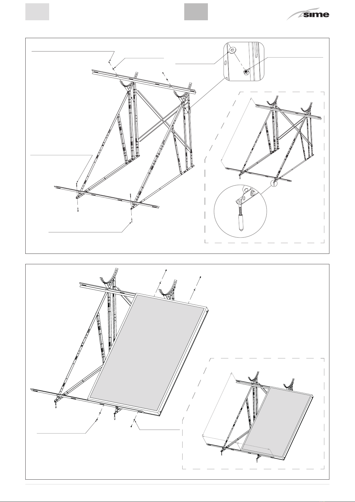
1.1.3 Installazione tetto a falda1.1.3 Installation on a sloping roof
Fig. 16

18
ITEN
31X
22X
12X
31X
Fig. 17
12X
L=1000 mm (C)
L=2000 mm (3)
L=1370 mm (A)
L=1110 mm (B)
Fig. 18
MONTAGGIO DEI COMPONENTIASSEMBLY OF COMPONENTS

19
ITEN
22X
Fig. 19
31X
2x Hexagon
head bolt
M8 x 20mm
2x Bullone a
testa esagonale
M8 x 20mm
4x Washer M8
4x Rondella M8 2x Hexagon nut M8
2x Dado esagonale M8
2x Washer M8
2x Rondella M8
2x Hexagon nut M8
2x Dado esagonale M8
2x Bullone a testa esagonale
M8 x 20mm
2x Hexagon head bolt M8 x 20mm
2x Washer M8
2x Rondella M8
2x Code 5801600
2x Cod. 5801600
2x Code 5801600
2x Cod. 5801600
Fig. 20

20
ITEN
2x Bullone a testa esagonale
M8 x 20mm
2x Hexagon head bolt M8 x 20mm
2x Washer M8
2x Rondella M8
Fig. 21
2x Bullone a testa esagonale
M8 x 20mm
2x Hexagon head bolt M8 x 20mm
2x Washer M8
2x Rondella M8
Fig. 22
This manual suits for next models
3
Table of contents
Other Sime Water System manuals


Popular Water System manuals by other brands


Schwan
Schwan SC60E user guide

Addie Water Systems
Addie Water Systems OXIDIZER PLUS owner's manual

US Water Systems
US Water Systems USCRO-350 Installation and operation manual

Presto
Presto Q4357 installation instructions

FLOJET
FLOJET LF Plus Series installation guide

Webasto
Webasto BLUE COOL Operation manual


