Fonderie Sime SpA reserves the right to amend all of the product and relative accessories specifications without prior warning.
38 39
ENG
FR
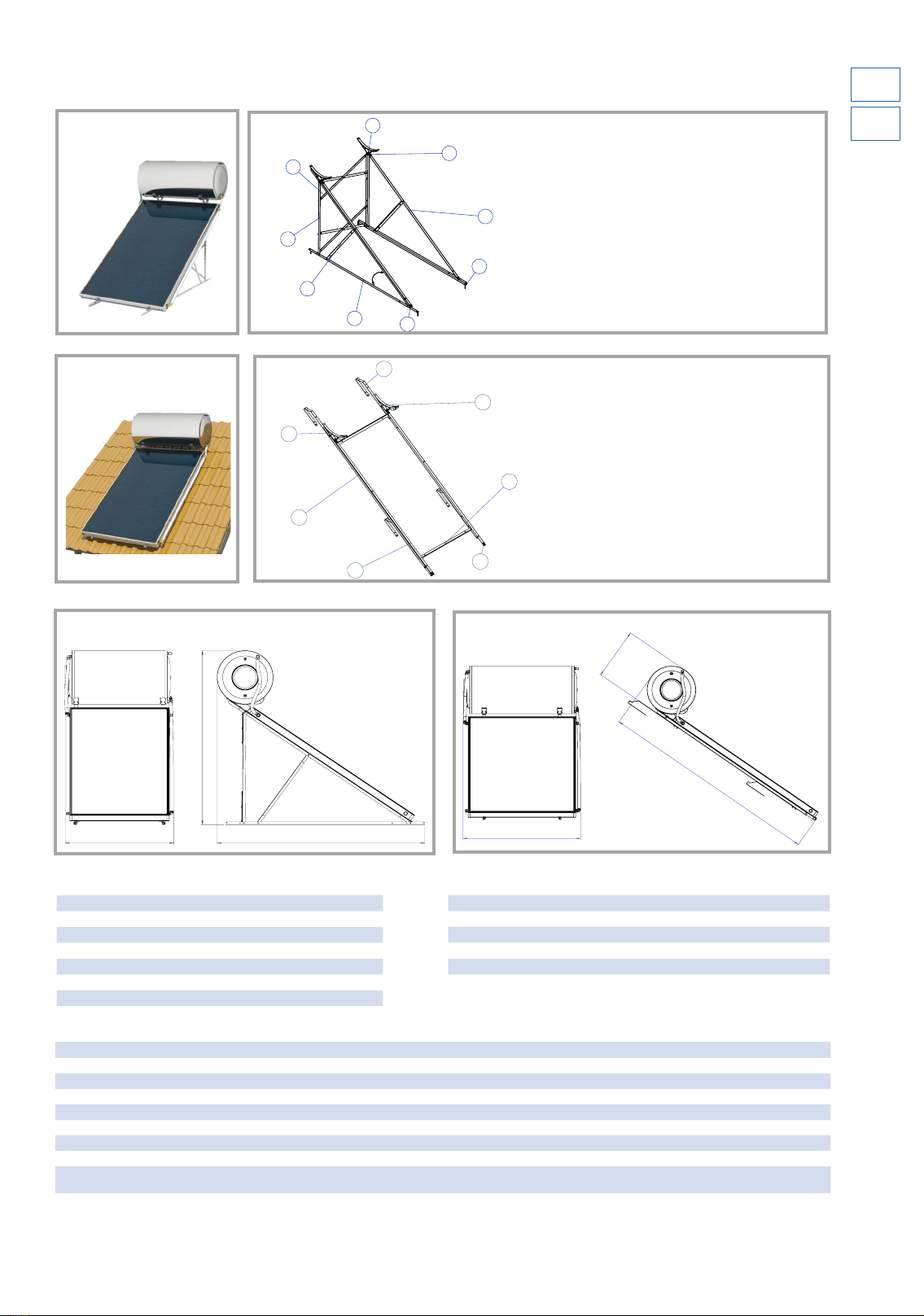
GENERAL INSTALLATION RULES
ATTENTION:
Installation must be conform to the local standards in force for hydraulic and electric plants.
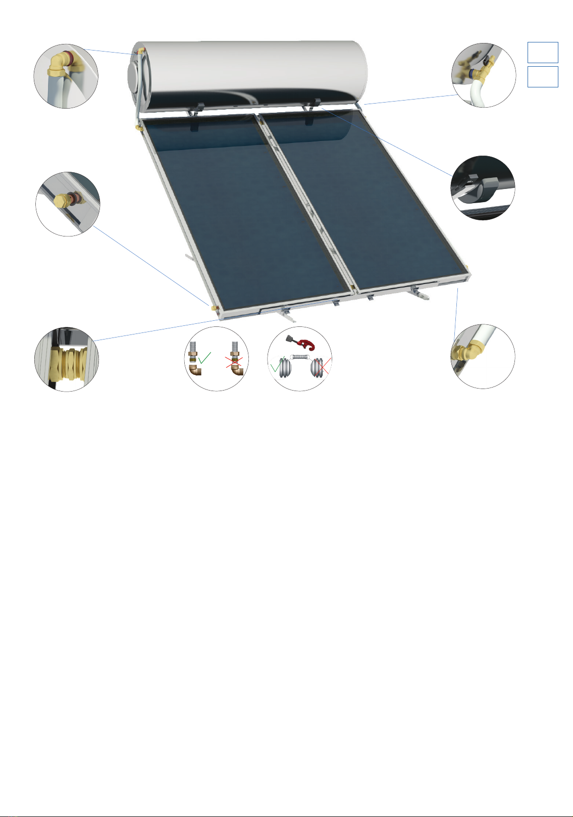
Remove the water heater packaging in the place of installation to protect the equipment against impacts during transport,
avoiding resting the collectors' weight on the pipes connection fittings. The collectors' crystals must remain covered until in-
stallation is completed, until the boiler is filled with domestic water to avoid the filling liquid from boiling or the crystals from
breaking. Remove the plastic protective caps from the boiler and collectors' connection fittings.
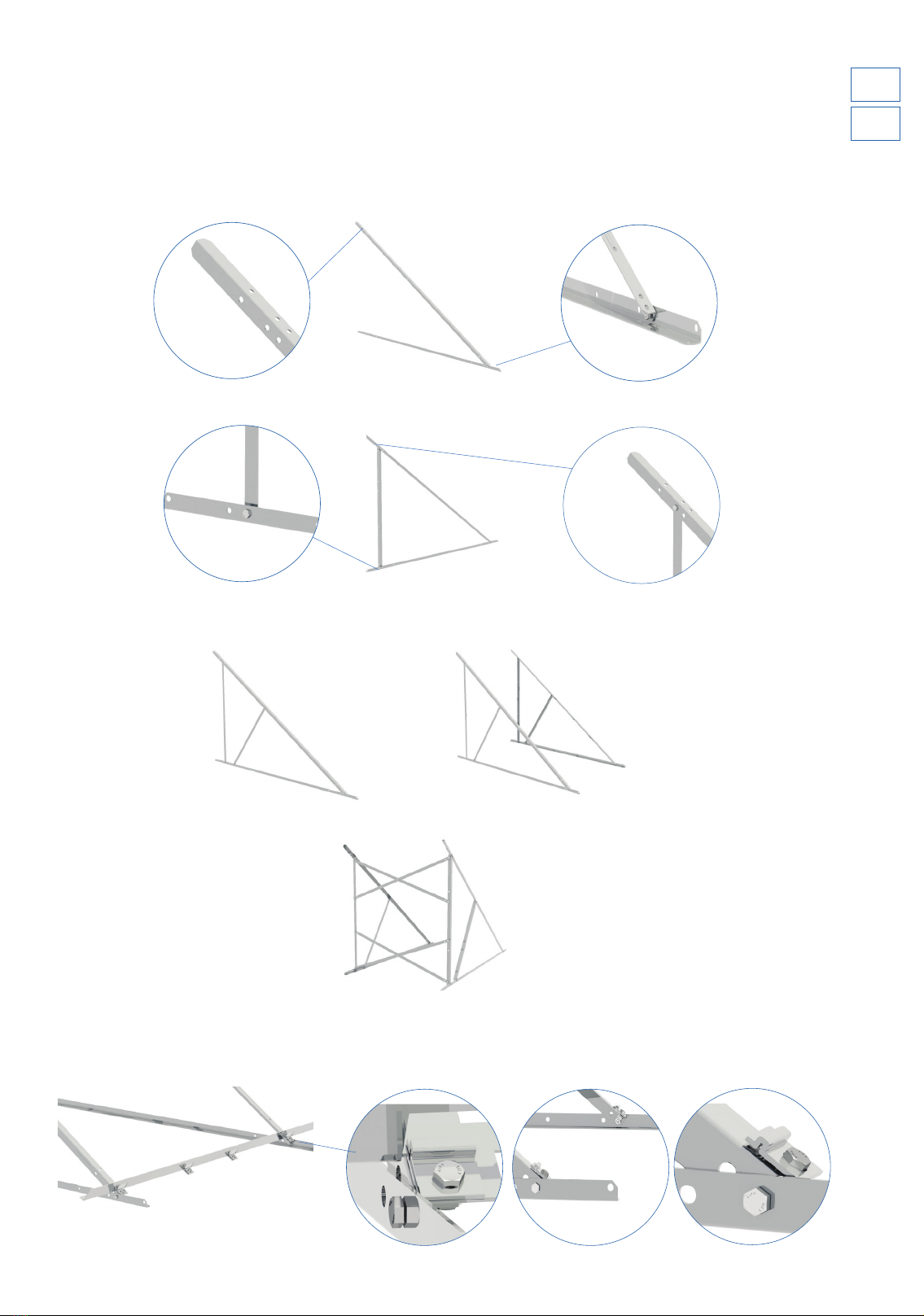
Installation point: the installer must accurately choose the place of installation before proceeding, (in agreement with the cus-
tomer). It is also necessary to check (considering the static resistance) that the surface is able to support the system's weight.
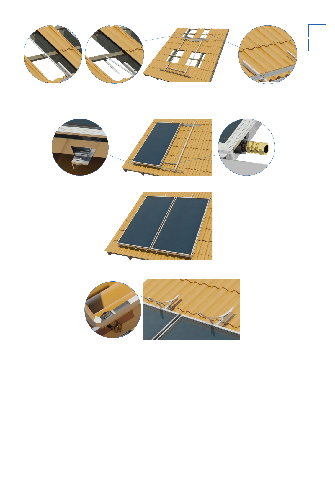
On inclined roofs, the system must never the placed between two beams but above a single beam.
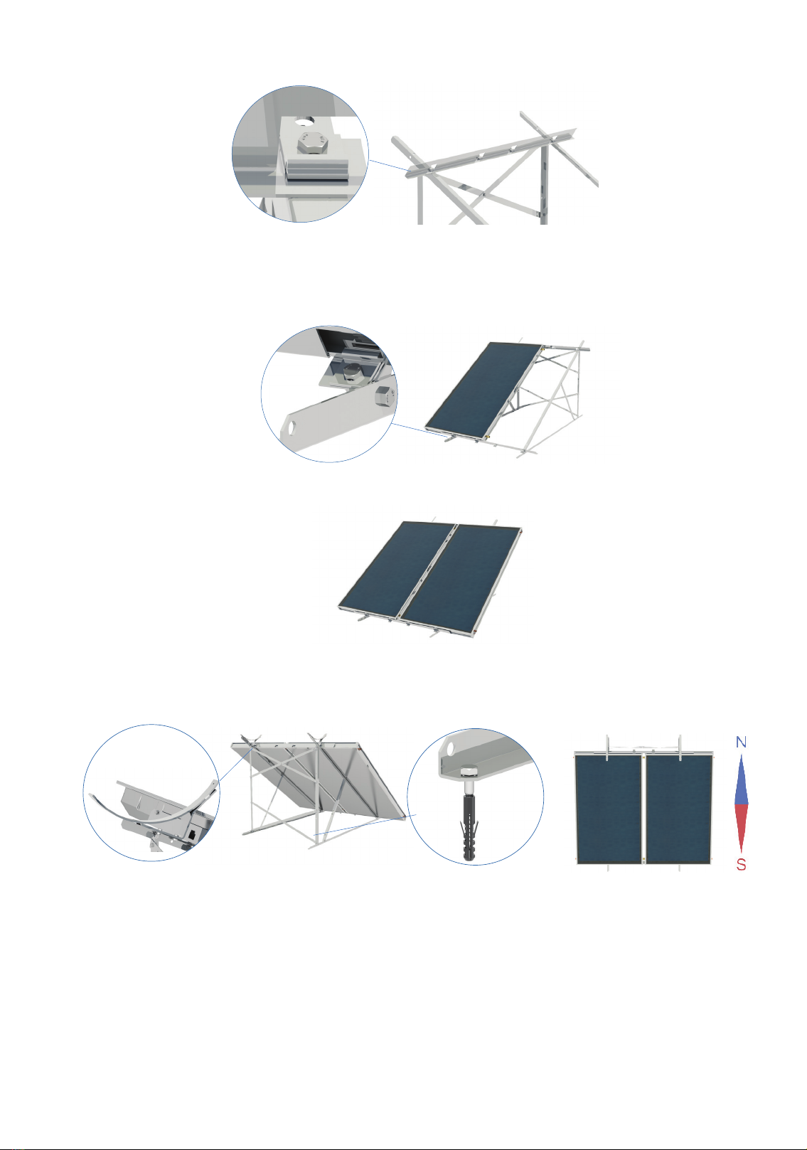
Direction - Perfect inclination - Shading: It is essential, in order to obtain maximum solar system yield, to properly choose the
inclination and direction with regard to the installation place and the maximum production period requested. The solar panels must
be directed so that their surface faces the geographic South in the northern hemisphere (geographic North in the southern hemi-
sphere), meaning they always face the equator.
A change of direction means a decrease in the plant's yield. Correct the system yield if the change of the correct direction is inevi-
table, by increasing the collectors' surface based on an assessment of the specific conditions.
As the angle of incidence of the solar radiation changes with the season and with the system's place of installation, the collectors'
angle of inclination must be almost equal to the place of installation latitude. This inclination gives a maximum annual energy
production. Avoid the system being shaded by trees,
buildings, other obstacles in order to guarantee the
collectors' surface to at least 4 hours of full exposure
of solar radiation during midday.
Installation specification: should the installation
surface of the solar heater (inclined or flat) not be
compatible with the standard equipment supplied
with the system, a different type of equipment must
be used.
The installer is responsible for choosing the equip-
ment. The company is in no way responsible. Prior
agreement with the customer, the installer is re-
sponsible for proposing and installing the different
equipment required.
Particular atmospheric conditions: it is necessary
to make sure that, in regions characterised by heavy
snow, this is immediately removed. In this case and in
regions affected by storms, strong wind, heavy show-
ers, cyclones and tornado, the system to be placed on
the roof must be as stable as possible and secured
with further metal straps.
We recommend stipulating an insurance policy for the solar water heater in areas where these conditions occur and hailstones
larger than 20 mm are seen. However, we recommend fixing the solar water heater to the basic support system using more metal
belts than supplied.
LATITUDE DISTANCE BETWEEN OBSTACLE AND COLLECTOR
(L)
0o - 25o1.0 x H
26o - 35o1.5 x H
36o - 45o2.0 x H
46o - 50o2.5 x H
> 50o3.0 x H