Simer A5300 User manual

©2016 SIM979 (Rev. 12/31/16)
OWNER’S MANUAL
Battery Backup System
NOTICE D’UTILISATION
Système de secours à batterie
MANUAL DEL USUARIO
Sistema de batería de respaldo
PumpActivity
Activitéde pompe
Actividadde la bomba
SystemAlert
Alertedu système
Alertadel sistema
ACPower
CourantAC
CA
Charging
Recharge
Encarga
BatteryStatus
Étatde batterie
Estadode la batería
AlarmSilenced
Alarmearrêtée
Alarmaapagada
TestSystem
Tester
Probarsistema
SilenceAlarm
Arrêterl’alarme
Apagaralarma
Light
Lumière
Luz
CircuitBreaker
Disjoncteur
Disyuntor
Pump
Pompe
Bomba
FloatSwitch
Interrupteurà flotteur
Interruptordel flotador
Power
Courant
Encendido
ResetSystem
Réinitialise
Restrablecersistema
+
6975 0515
A5300
Installation/Operation/Parts
For further operating, installation,
or maintenance assistance:
Call
800-468-7867
English........................... Pages 2-17
Installation/Fonctionnement/Pièces
Pour plus de renseignements
concernant l’utilisation,
l’installation ou l’entretien,
Composer le
(800)
468-7867
Français .................... Pages 18-32
Instalación/Operación/Piezas
Para mayor información sobre el
funcionamiento, instalación o
mantenimiento de la bomba:
Llame al 800-
468-7867
Español..................... Paginas 34-49
Device ID Key

Safety 2
Important Safety Instructions
SAVE THESE INSTRUCTIONS - This manual contains
important instructions that should be followed during
installation, operation, and maintenance of the product.
This is the safety alert symbol. When you see this
symbol on your pump or in this manual, look for one of
the following signal words and be alert to the potential
for personal injury!
indicates a hazard which, if not avoided,
will result in death or serious injury.
indicates a hazard which, if not avoided,
can result in death or serious injury.
indicates a hazard which, if not avoided,
can or may result in minor or moderate injury.
NOTICE addresses practices not related to personal injury.
Carefully read and follow all safety instructions in this
manual and on pump.
Keep safety labels in good condition. Replace missing or
damaged safety labels.
To avoid risk of serious bodily injury due to electrical
shock or burns and property damage due to flooding,
read the safety instructions carefully before installing
pump.
Battery acid is corrosive. Do not spill on
skin, clothing, or battery charger. Wear eye and head
protection when working with battery. Connect and
disconnect DC output terminals only after removing the
charger from the AC outlet. Never allow the DC
terminals to touch each other.
Hazardous Voltage. Can cause severe or
fatal electrical shock. Do not plug in or unplug battery
charger while standing on a wet floor or in water. Be sure
one hand is free when plugging in or unplugging charger.
If basement floor is wet, disconnect power to basement
before walking on floor.
Risk of flooding. Do not run pump dry. To
do so will damage seals and can cause leaking and
property damage.
Follow local and/or national plumbing and electrical
codes when installing the system. A ground fault circuit
interrupter (GFCI) is recommended for use on any
electrical appliance submerged in water.
Use this system only for backup sump pump duty in a
residential application. It is not designed as a primary
sump pump.
Do not lift pump by electrical cord.
Risk of electrical shock. Do not lift the
pump by the electrical cord; lift pump only by the
discharge pipe, lifting ring or handle on the pump. Lifting
by the cord can damage the cord.
Pump clear water only with this pump.
Pump is permanently lubricated at the factory. Do not try
to lubricate it!
Keep battery charger and battery box off of the floor and
in a dry, cool, well ventilated area.
NOTICE: If a Carbon Monoxide (CO) sensor is installed,
it must be at least 15 feet away from battery charger
in order to avoid nuisance CO alarms. Please refer
to your CO detector’s installation guidelines for more
information.
To avoid danger of fire or explosion, keep sparks and
flame (pilot light) away from battery.
Maximum vertical pumping distance is 15 feet (4.6M) for
Model A5300.
Make sure sump is clear of debris. Debris can damage
the pump which can result in flooding.
California Proposition 65 Warning
This product and related accessories contain
chemicals known to the State of California to cause
cancer, birth defects or other reproductive harm.
GENERAL INFORMATION
The battery backup sump system is not a substitute for
your primary sump pump. It is designed to temporarily
backup your primary sump pump during a power outage
or other problem which prevents normal operation of
the primary pump. Do not use this system to pump
flammable liquids or chemicals. Pump clear water only
with this pump.
Keep the battery charger dry and protected from damage.
This system is designed to work with a deep cycle sealed
maintenance free lead-acid AGM battery. It will also
work with a flooded lead acid battery. Gell and Sealed
flooded lead acid batteries are not recommended. In
an emergency (such as an extended power outage)
which depletes the system deep cycle battery, your
automobile battery may be temporarily substituted. Be
sure to replace the system deep cycle battery as soon
as possible. Use of an automobile battery instead of a
deep cycle battery in this system will significantly reduce
the system’s total performance. Automobile batteries
are not designed for this type of application and will be
quickly ruined by the repeated charge/discharge cycling.
NOTICE: This system is not designed for applications
involving salt water, brine, or where fish may be present!
Use with these will void warranty.

Installation 3
BASIC TOOLS AND PARTS NEEDED
(Purchase Separately)
Tongue and groove or
large adjustable pliers
Tape measure
Socket wrench or 5/16”
nut driver
Side cutters
Hacksaw (to cut PVC
pipe)
Medium size pliers
Slotted screwdriver
Phillips head screwdriver
Pencil or marker
PTFE pipe thread sealant
tape
PVC glue (solvent weld)
PVC pipe cleaner
Cloth towel
Plastic fittings
Check valve(s) - 1 or
2 depending on
installation
38-120 Ampere-Hour
Storage or Deep Cycle
Battery
Required Battery Capacity:
For best results, use the following AGM Storage Batteries:
Part Amp-Hour
Gal/Charge
at 10’
Approx Run
Time
BAT40 40 4,800 5 Hours
BAT75 75 11,500 11.5 Hours
• Unit equipped with dual battery capability
• Maximum amp-hour: 120
NOTICE: The charger will not fully charge batteries with
excessive amp hour ratings without resetting system.
BATTERY BACKUP SYSTEM (BBU)
INSTALLATION AND OPERATION
NOTICE:
• Install this system during a time when the primary
pump will not be needed. Gather all supplies before
starting. Read all warnings and installation steps
before you start.
• Be prepared for water to leak from the coupling or
piping when disassembling or cutting the discharge
pipe. Protect system components, tools and supplies
from getting wet. Dry any work areas that get wet.
NOTICE: Determine which installation method will
be best for you. The “Separate Discharge” (Figure 7)
installation is recommended.
NOTICE: Check your local codes and ordinances
regarding waste water disposal (especially when running
the pump discharge outside the house) before you start.
The installation must conform to all legal requirements.
If possible, install the BBU so that the discharge goes
directly outdoors (separate discharge pipe from the
primary sump pump discharge pipe). If this is not a
practical option, see the “Easy Install – Method A” option.
NOTICE: For ALL installations, once the installation is
complete, see page 12 for Link2O setup and complete
the registration and connection process. Run both the
primary sump pump and the BBU through at least one
complete cycle to make sure that everything operates
correctly.
Personal injury and flood hazard. Do not
turn the pump on until all the fittings are glued and the
glue has dried. Loose fittings can explode off of pipes
and cause personal injury and flooding.
Risk of electrical shock. At the circuit breaker
or fuse box, turn off the electrical power to the sump
pump before beginning this installation.
SETUP – COMMON DISCHARGE
1. Locate the high water level in your sump pit (the
water level at which the existing (primary) sump
pump starts - see Figure 1). Turn off power to pump
and mark this point on the discharge pipe with a
pencil or marker.
2. Drain the sump pit as far as possible without running
the pump dry. Do this by:
A. Piggyback switch: Unplug the pump and switch
from the outlet, then unplug the pump from the
piggyback switch. Reset the circuit breaker or
reinstall the fuse and plug the pump directly into
the outlet. The pump will start. Drain the pit and
unplug the pump. OR
b. Nopiggyback switch: Reset the circuit breaker
or reinstall the fuse and use a non-conducting
broom handle or stick to raise the float switch;
the pump should start. Drain the pit and then
release the switch.
3. When the pit has drained, turn off (open) the circuit
breaker or remove the fuse again to avoid electrical
shock while working on the installation.
'Turn on'
water level of
Primary Pump
Sump Pit
Check
Valve
Remove the
hose coupling
or mark the
1st cut here.
Support the pipe
before cutting.
3547 1016
Mark pipe with
pencil here
(2nd cut).
Figure 1 – Mark and cut pipe as shown

EASY INSTALL – METHOD A
The recommended Easy Install method suggests installing
both of the pumps on the floor of the sump pit. See
Figure 2. The minimum required sump basin diameter at
the bottom of the pit and the recommended depth of the
sump basin is 18”.
Some additional materials you will need are (2) 1-1/4”
NPT 90° elbows and (2) 1-1/4” NPT close pipe nipples.
Second Cut:
at Marked
Water Line
First Cut:
Backup Pump Installation
(Method A)
Not to Scale
Switches and
Wiring omitted
for clarity
1-1/2" x 1-1/4"
Reducer bushing
for 1-1/4" pipe
1-1/2" x 1-1/4"
Reducer bushing
for 1-1/4" pipe
Tee
1-1/2" x 1-1/2"
slip x 1-1/4" FNPT
Short Length
of Discharge Pipe
(may vary)
Primary Sump
Pump Check Valve
to prevent
recirculation
into the sump;
required if not
already installed
on pump
Cut-Off piece of
discharge pipe.
Hose Coupling
with Clamps
1-1/4" Elbow
1-1/4"
Elbow
Close
Pipe
Nipple
(1-1/4"
x 1-1/4")
Back-up Pump
Discharge Port
Primary Pump
Discharge Port
(1 Nipple
is included
with the
back-up
pump
package)
6977 0515
Check Valve
Assembly
Battery
Backup
Switch*
Figure 2 - Installation diagram – Method A
1. Make the second cut in the discharge pipe at the
pencil mark as shown in Figure 1. Clean the pipe
ends with a cloth towel and set the cut-off piece of
discharge pipe aside.
2. Thread a 1-1/4” NPT 90° elbow (purchased locally)
onto the discharge of the back-up pump.
3. Wrap the threads of all 3 of the close pipe nipples
with 2 turns of PTFE pipe thread sealant tape and
thread one of them into the elbow. Set the other 2
aside.
4. Thread the check valve assembly onto the close pipe
nipple.
NOTICE: Make sure the check valve is installed in the
correct direction. See the inset drawing in Figure 3.
Elbow
Back-up Pump
Discharge
Tee
6978 0515
Check
Valve
Assembly
Close
Pipe
Nipple
(The valve
flap opens
away from the
pump outlet)
Water
Flow
through
valve
Check Valve
Primary
required if
not already
installed
on pump
Figure 3 - Installation with close fit
5. Thread a close pipe nipple into the other end of the
check valve.
6 Thread the second 1-1/4” NPT 90° elbow onto the
pipe nipple.
7. Thread the last pipe nipple into the elbow.
8. Thread the tee onto the pipe nipple and set this
assembly aside.
9. Install a short length of pipe into the top of the check
valve in the primary pump discharge. See Figure 4.
NOTICE: There must be a check valve installed in the
Primary Sump Pump discharge pipe between the tee
and the Primary Sump Pump. This will prevent recir-
culation into the Primary Pump when the Backup
Sump Pump comes on.
10. Slip a reducer bushing (if required) onto the end of
the pipe coming from the primary pump discharge.
Do not glue this connection yet.
NOTICE: If your discharge pipe diameter is 1-1/4”,
you will need to glue the reducer bushings into the
tee first and then slip the cut off piece of discharge
pipe into the bushing.
11. Slip the tee and the back-up pump subassembly onto
the reducer bushing.
12. Glue the cut off piece of pipe into the top of the
reducer bushing in the top of the tee.
13. Mount the float switch assembly loosely to the
discharge pipe with the cable ties. See Figure 4.
Do not tighten the cable ties. Adjustments may be
needed later.
Installation 4

Installation 5
Check
valve
6979 0515
Primary
Sump Pump
Discharge Pipe
Tee
Hose
Coupling
and Clamps
Discharge
Pipe
Cable Ties
1-1/4 x 1-1/2”
Reducers
bushings
(if required)
2" Minimum
To the
back-up
pump
discharge
pipe.
Short length of
discharge pipe
(length may vary)
1-1/2"x1-1/2"
Slip Coupling
1-1/2"x1-1/2"
Slip Coupling
Auxiliary
Check Valve
Required
if a check
valve is
not already
installed
on pump
Figure 4 - Back-up pump float switch
METHOD B
1. Make a second cut in the discharge pipe at the
pencil mark made in step 1 and set the cut-off piece
of discharge pipe aside. See Figure 5.
2. Wrap the threads of the close nipple counterclock-
wise with 2 turns of PTFE pipe thread sealant tape
and set aside.
NOTICE: There must be a check valve installed in the
Primary Sump Pump discharge between the tee and
the Primary Sump Pump. This will prevent recircula-
tion into the Primary Pump when the Back Up Sump
Pump comes on. See Figure 5.
3. Thread the check valve onto the backup pump. Make
sure the check flap hinge is up and the flap swings
away from the pump.
4. Thread the close pipe nipple into the check valve
and pump assembly.
5. Thread the close nipple into the tee.
6. Repeat Steps 11, 12 and 13 above
Check
valve
6979 0515
Primary Sump
Pump Discharge
Pipe
Tee
Hose
Coupling
and Clamps
Discharge
Pipe
Cable Ties
2" Minimum
Short length of
discharge pipe
(length may vary)
1-1/2"x1-1/2"
Slip Coupling
1-1/2"x1-1/2"
Slip Coupling
Auxiliary
Check Valve
Required if
a check
valve is not
already
installed
on pump
Close
Nipple
Backup
Sump
Pump
Long End Faces
Pump, Short End
Faces Tee
Figure 5 – Method B – Make the second cut for
installation of the backup pump and check valve
assembly. Install the backup pump. Your installation may
not require the reducer bushings.
Check
Valve
Grounded
Electrical
Outlet
12" Min.
(305mm)
7" Min.
(178mm)
6980 1016
Hose Coupling
with Clamps
Coupling/
Check Valve
Assembly
Figure 6 – Double pump and float switch installation

Installation 6
INSTALLATION (TYPICAL): SEPARATE
DISCHARGE
Risk of electrical shock. Can shock, burn, or
kill. Unplug the primary sump pump before beginning
this procedure.
NOTICE: Allow for overlap when cutting piping and run a
trial (dry) fitting before you glue.
1. Use PTFE pipe thread sealant tape on male ends of
discharge pipe. Thread the 1-1/4” x 1-1/2” elbow
(supplied) onto the discharge. When tight, the elbow
must point up.
2. If possible, install the Battery Backup Unit (BBU) on
the floor of the sump; be sure that the two pumps do
not touch each other and do not interfere with switch
operation.
NOTICE: If debris or gravel is present in the bottom
of the sump pit that could get sucked up into the
pump, set both the primary sump pump and the BBU
up on bricks or cinder blocks to prevent clogging.
3. If the sump is too small to allow both pumps to sit
on the bottom of the sump, install an angle bracket
on the primary sump pump’s discharge pipe with
stainless steel hose clamps. Mount the backup
pump on the angle bracket. See Figure 7, “Separate
Discharge”.
4. Cut a piece of 1-1/2” PVC pipe to reach from the
backup pump discharge elbow to about one (1) foot
above the basement floor. This is the lower discharge
pipe.
5. To prevent airlocking the pump during operation,
drill a 1/8” hole in the lower discharge pipe about 2”
above the bottom of the pipe (below floor level).
6. Install FP0026-10 check valve (purchase separately)
on the upper end of the pipe. Tighten the hose
clamps securely. BE SURE that the flow arrows point
UP (away from the BBU). If they point down, the
valve will not pass water and the pump will not work.
7. Cut a short length of 1-1/2” PVC pipe for a riser pipe
and clamp it into the top of the check valve.
8. Install a U74-68 Hose and Clamp Assembly on the
top of the riser pipe. For 1-1/2” pipe, remove and
discard the short piece of 1-1/4” hose in the Hose
and Clamp Assembly. Leave the hose clamps loose
and slide the Assembly down below the top of the
riser pipe.
9. Determine where you want the discharge to exit the
basement. At that point, drill the necessary holes
(large enough to have clearance for a 1-1/2” pipe) to
allow you to run the discharge pipe from above the
sump to the outdoors.
10. Install the horizontal discharge pipe. Install a 90°
elbow on the inside end but do not glue.
11. Cut another short piece of 1-1/2” PVC for the Upper
Discharge Pipe to run from the top of the riser pipe
up to the 90° elbow. Be sure to allow enough overlap
for the glue joint in the elbow.
12. Do a trial fit with NO GLUE, installing the 1-1/2”
upper discharge pipe in the 90° elbow and the upper
discharge pipe in the vertical end of the 90° elbow.
The upper discharge pipe should just fit between the
riser pipe and the elbow.
13. Risk of fire and chemical inhalation.
Whenever using PVC primer and PVC cement, follow
the glue manufacturer’s instructions.
14. Make sure that the BBU will clear the primary sump
pump and its switch. If there isn’t room for both
pumps to sit on the floor of the sump, the BBU will
have to be raised (depending on your particular situ-
ation).
15. Clean, prime and glue the upper discharge pipe
into the 90º elbow. When the glue has set, slide the
Hose and Clamp Assembly up to cover the joint and
tighten all the hose clamps.
16. Install the Battery Backup Switch as shown, 1” above
start water level of primary pump. Fasten it to the
pipe with cable ties.
17. Tape the pump cord to the riser pipe so that the plug
cannot fall into the sump.
18. Go to “BBU WIRING AND SETUP” (Page 10) for
wiring instructions.
19. Once all wiring is complete, fill your pit with water
and verify that the PSP removes the water and the
BBU doesn’t run. Then, unplug your PSP and refill
your pit with water. Verify that the BBU pump
removes the water.
20. Make sure that the power is on to both pumps, and
your system is ready to use.

Installation 7
“Separate Discharge”
NOTICE:
Check Valve Flapper(s) must swing AWAY and flow arrow(s) must point
AWAY from pump being protected.
The water level when the switch shuts off must be above the BBU
pump intake.
*Supplied with the Battery Backup System.
Items in italics must be purchased separately.
FLOW
Slope DOWN
to outlet Sill
PTFE pipe thread
sealant tape on all
threaded joints
1-1/2” PVC Riser Pipe
(cut to fit)
1-1/4” FNPTx1-1/2” Slip
Elbow*
Battery Back Up
Sump Pump*
Lower Discharge Pipe
1-1/2” PVC Pipe
(cut to fit)
(2) 1-1/2” PVC
Coupler*
Primary Sump Pump
Check Valve
Check Valve*
Flow Arrow; Must point
AWAY from Pump
being Protected
1-1/2” PVC Upper
Discharge Pipe
(cut to fit)
Battery Backup
Switch*
If the sump is small,
hang the BBU from
the Primary discharge
pipe on an angle bracket.
Floor
Joist
U74-68 Hose and
Clamp Assembly*
Drill 1/8” Anti-Airlock
Hole
6782 1016
Not to scale.
Wiring omitted for clarity.
Figure 7: Typical installation with separate discharge
pipes.

Battery Requirements 8
BATTERY REQUIREMENTS
Hazardous electric current. Can cause
severe burns and start a fire if the battery terminals are
short circuited. Install the battery in the battery case. To
prevent accidental shorting across battery terminals,
close and latch the battery case securely. Do not leave
the battery uncovered.
Do not allow children to play around the battery
backup system installation.
The performance of your backup sump pump depends on
the battery used with it for power. We recommend using
our BAT40 or BAT75. You can also use a group 24M or
27M Deep Cycle battery. They will provide acceptable
performance and will stand up well to long periods of
little or no use.
This system is designed to work with either a sealed
lead-acid AGM battery or a flooded lead-acid battery.
Use of a true Gell Cell (often confused for AGM) or a
standard automotive battery with this charger is not
recommended. An automotive battery may require
charging after only 1-2 hours of continuous use, and the
repeated charging cycles may cause early plate failure in
the battery.
Use only lead-acid batteries. This unit is not designed to
use with Li-Ion, NiMh, NiCAD, Liquid Polymer, etc.
Use only the recommended battery or one of the same
type and size so it will fit in the battery box (maximum
size: 13” long x 7” wide x 10” tall (330.2mm x 177.8mm
x 254mm) including terminals) and supply enough
voltage for full performance.
BATTERY MAINTENANCE
Severe burn hazard. An acid-filled standard
lead-acid battery contains sulfuric acid. Avoid contact with
skin, eyes or clothing.
NOTICE: To protect the battery case from chipping and
gouging, do not let the battery sit on a concrete floor.
Install the battery on a shelf or protective pad (plywood,
2x4s, etc.). Always install the battery in a dry location
that is protected from flooding.
Pre-Qualification Test – 1 and 2
Charger is charging at a very low level to try to bring a
dead battery back to life. If the battery is taking too long,
try resetting the charger once or twice (push the ‘SYSTEM
TEST’ and ‘SILENCE ALARM’ buttons together to reset the
charger).
Special Features:
The charger is equipped with reverse battery, short
circuit, and “runaway charge” protection.
Possible Problems and Remedies
1. Wrong Battery Voltage
Reconnect charger to a 12 volt battery.
2. Reversed Battery Connections
Check all connections. The negative (black) on the
battery must connect to the negative (black) on
the charger, and the positive (red) on the battery
must connect to the positive (red) on the charger.
Reversing the battery connections will cause the
‘SYSTEM ALERT’ and ‘SILENCED AUDIBLE ALARM’
LEDs to flash.
3. Thermal Runaway Condition
“Thermal Runaway” is the technical term for the
condition of the battery when some (or all) of the
cells have deteriorated to the point that they won’t
take a charge. In this case, replace the battery.
4. Charge Time Monitor – 1 and 2
Battery took too long to complete its charge. The
“Charge Time Monitor” will shut down the charger
after 84 hours of continuous charging.
Possible causes are:
A) Pump ran for a long period of time during
charging, or
B) Battery is too large for the charger (including
several batteries connected in a parallel circuit).
Excessive Battery Drain
Pump may have run for a very long time, discharging the
battery. In this case:
1. If 115VAC power is OFF, the charger shuts down
until the power comes back on, but the pump will
run as long as the battery charge lasts. You may need
to replace the battery afterwards.
2. If 115VAC power is ON, the charger/controller
continues to try to charge the battery at a charging
rate of .5 AH until the battery charge is more
than 20%, at which point the charger will resume
charging at a rate of 2 AH.
3. If the pump is running and the AC power is on, you
may need to stop the pump to allow the battery to
charge.
Follow the battery manufacturer’s recommendations for
maintenance and safe use of the battery.

Wiring •Setup 9
6981 1216
BBU WIRING AND SETUP
1. Connect the positive (+) charger/controller lead
wire (red) to the positive (+) battery terminal (red).
Connect the negative (–) charger/controller lead
wire (black) to the negative (–) terminal (black) on
the battery. If you are using two batteries, use the
set of optional terminals and connect the second
battery. Use lead wires (not included) to connect
the positive (+) charger/controller terminal to the
positive (+) battery terminal and the negative (–)
charger/controller terminal to the negative (–) battery
terminal.
2. The backup pump leads are polarity sensitive;
connect the positive pump lead to the terminal
labeled Pump ‘+’ and the negative pump lead to the
terminal labeled Pump ‘–’.
NOTICE: If the leads are reversed, the pump will run
backward and not pump water.
3. The float switch leads are not polarity sensitive;
connect the float switch leads to the ‘Float Switch’
tabs on the charger/controller.
4. Test the float and the pump by lifting and holding
the float. The system alert LED will blink while
the float is up. The ‘PUMP STATUS’ LED will light
continuously and the buzzer will beep steadily. The
pump should start after 3 seconds. If the pump does
not run, check all the connections and remake them
as necessary.
5. To stop the pump, lower the float; after 25 seconds
the pump should stop, the ‘PUMP STATUS’ LED
should flash, and the buzzer should beep.
6. With the pump operating, test the ‘SILENCE ALARM’
button; hold for one second; release. The ‘ALARM
SILENCED’ LED should illuminate and the buzzer
should stop sounding. To reset the buzzer (allow it to
sound) and extinguish the ‘ALARM SILENCED’ LED,
press the ‘SILENCE ALARM’ button again for one
second.
Depress the ‘TEST SYSTEM’ button; hold it for one
second; release. The ‘PUMP STATUS’ LED should stop
flashing.

Wiring •Setup 10
NOTICE: When the unit is first plugged in, or when it first receives power from the battery, the ‘BATTERY STATUS’
LED will flash for 3 seconds.
NOTICE: To activate any Control Button, press and hold it for 1 second.
LED Display and Control Buttons
NOTICE: During normal operation, the flashing
‘PUMP STATUS’ LED indicates that the pump has
run in your absence.
1. Press and hold ‘TEST SYSTEM’ button. All LEDs will
light up, pump will run and buzzer will sound.
Release the button and LEDs should go off, pump
should stop, buzzer should stop.
2. The ‘BATTERY STATUS’ LED indicates the battery
capacity when the A.C. power is off.
A. Continuously ON - the battery voltage is above
10.9 Volts Direct Current (10.9VDC) and
capacity is above 20%.
B. Slow Beep/Slow LED Flash - the battery’s
capacity is between 0 and 20%.
C. Fast Beep/Fast LED Flash - the battery is severely
discharged. The battery will continue to charge
(as long as the 115V AC power to the charger is
on) at the rate of .5 AH until the battery’s charge
is above 20%.
When the first warning occurs (slow beep/slow
flash), you will have approximately 2 hours (or less)
of pump operation left. The actual time of operation
will depend on the condition of the battery and may
be as little as 15 minutes.
4. Connect the Power Supply cable (supplied) to the
Charger/Controller’s Power Input jack.

BATTERY BACKUP INTERNET
CONNECTION AND ALERTS
CONFIGURATION
1. Complete the Battery Backup Registration, Internet
Connection and Alert Configuration BEFORE con-
necting the battery and AC power supply to your
BBU.
NOTICE: If you have already connected the battery
and AC power supply to the BBU before connecting
to to the internet, complete the device registration
process. Then disconnect the battery and remove the
AC power supply from the BBU panel and gateway
for 2 minutes in order to reset the panel. Resume
with Step 8.
2. Go to mylink2o.com and select “sign up” (or Login if
you have an existing account).
3. Follow the online instructions and enter the required
personal information to create a new user account.
4. Register your device using the Unique Device ID Key
included on the device and your manual cover.
5. The Alerts will use the e-mail(s) and phone number(s)
entered here.
6. Find an open network connection on your internet
router or other hardwired connection (like an internet
switch).
7. Rotate the Gateway antenna up on the gateway. Us-
ing the supplied 1 meter Ethernet cable (or a longer
cable if necessary) Connect the Gateway to the open
internet port.
NOTICE: We recommend the use of an uninterrupted
power supply for your internet modem, home router,
internet switch (if applicable), and the gateway power
supply.
8. Connect the Gateway power supply to a 115 VAC
outlet, plug the cord into the back of the Gateway.
• The Gateway will blink red for a few seconds.
• When the LED becomes solid Green or solid
Green with an occasional blink – your Gateway
is communicating with the Link2O server. If not,
refer to Gateway Trouble in the manual.
9. Connect the red positive (+) charger/controller lead
wire to the positive (+) (red) battery terminal. Con-
nect the black negative (-)charger/controller lead wire
to the negative (-) (black) battery terminal.
10. Connect the Charger Power Supply cable (supplied)
to the Charger/Controller’s Power input jack. Plug
the other end into a 115 VAC outlet.
11. Check the AC power LED on the Controller – if it is
solid green the unit is communicating with the WEB
site.
12. Verify the system is operational by pressing the ‘TEST
SYSTEM’ button and observing the test sequence.
13. Test communication by clicking the “Test” icon on
the web page and verify the unit has run the test.
14. Using the drop down menu configure the desired
method of Alerts you want to receive (Text or E-mail).
15. Alerts can be tested by activating the pump with the
float switch.
Link2O™Setup 11

IF GATEWAY LED LIGHT IS NOT GREEN (GREEN, SLOW BLINK) FIRST TRY TO “POWER CYCLE” THE GATEWAY (UNPLUG THE
POWER CORD, WAIT 15+ SECONDS, THEN RE-APPLY POWER).
Gateway Status
Indicator (LED Color)
Definition Action Needed
Green Power on: gateway connected to servers. OK - Connection complete and operational
Green, quick blink Power on: data traffic to servers. OK - Operating, data is moving between BBU and
Server
Green, slow blink
(1-2 blinks per second)
Power on: gateway connected to local router, but
not connected to Internet or servers.
System is online and scanning for destination/server
(add a network switch inline to help define unit).
Red Power on: gateway has no local connection to
router. The gateway does not "recognize/see" that it
is connected to the router.
Check Ethernet cable connections and/or quality or
cable. Try a different router port. Is the router turned
on.
Red, slow blink
(1-2 blinks per second)
Power on: gateway communicating with router, but
router cannot assign Dynamic Host Configuration
Protocol (DHCP) or Domain Name System (DNS) to
gateway.
Router is not permitting the gateway to access the
internet (add a network switch inline to help define
unit).
Off Power off or product fault. Check power source, verify power adapter is
functioning. Defective gateway.
GATEWAY TROUBLESHOOTING
Link2O™Setup Setup 12

Charger/Controller LED Display 13
LED Operating Code Display System Operating Condition
CHARGING
BATTERY STATUS
PUMP ACTIVITY
AC POWER
ALARM SILENCED
SYSTEM ALERT
Indicates 115V AC Power is connected / Unit online
NOTICE: All of the situations listed above indicate normal system operation; no action is required.
However, if the BBU pump is running or has run, check the primary pump and actively monitor the
charger status for battery life. Always reset the charger after the pump runs.
During normal system operation, the ‘SYSTEM ALERT’ LED blinks while the float switch is on,
indicating the pump should start within 3 seconds. The “AC POWER” LED is lighted
(solid or blinking) as long as the system is plugged in to an operating AC power circuit.
Indicates Pump is running (continuous LED)
Indicates Audible alarm is switched off
Indicates Battery is charging normally
Indicates Continuous LED: battery charge is above 20%,
system is maintaining charge
Indicates Slow flashing LED: battery charge is below 20%
6790 0313
LED is Flashing (Slow)
=LED is OFF
LED is ON Continuously
= =
LED is Flashing (Fast)
=
Indicates Fast flashing LED: Pump has run
Indicates Fast flashing LED: Battery pre-qualification test is running
Indicates 115V AC Power is connected / Unit offline
NOTE: When the System Alert light IS NOT flashing, refer to Table II. When the System Alert light
IS flashing, refer to Table IV
TABLE II – Operating Code Displays (LEDs Lighted Continuously or Flashing)
TABLE III – LED Function Displays (LEDs Lighted Continuously)
Control LED: Continuous Illumination Indicates Normal Operation:
AC Power AC power is present. Unit is online.
Pump Status
The float switch has been activated. The LED remains on (flashing) after the pump
has stopped. Depress the ‘SYSTEM TEST’ button to reset it.
Silenced Audible Alarm Audible Alarm has been silenced. Press and release the ‘SILENCE ALARM’ button
to reset (activate) the audible alarm and turn OFF the LED.
Charging
Indicates that the battery is charging – see Table II, above.
Battery Status A. Continuous ON - the battery voltage is above 10.9 Volts DC and capacity is
above 20%.
B. Slow Beep/Slow LED Flash - the battery’s capacity is below 20%, and voltage is
between 8.2VDC and 10.9VDC.
C. Fast Beep/Fast LED Flash - the battery has been discharged to less than 8.2VDC.
System Alert Flashing (in unison with the buzzer) indicates that the charger has entered ‘Failure
Mode’. Press the ‘SYSTEM TEST’ and ‘SILENCE ALARM’ buttons to reset it.
NOTICE: If the source of the failure is not corrected, the charger will reenter
“Failure Mode”. See Table IV for error code information.
Charger/Controller LED Display 14
NOTE: When the System Alert light IS NOT flashing, refer to Table II. When the System Alert light
IS flashing, refer to Table IV
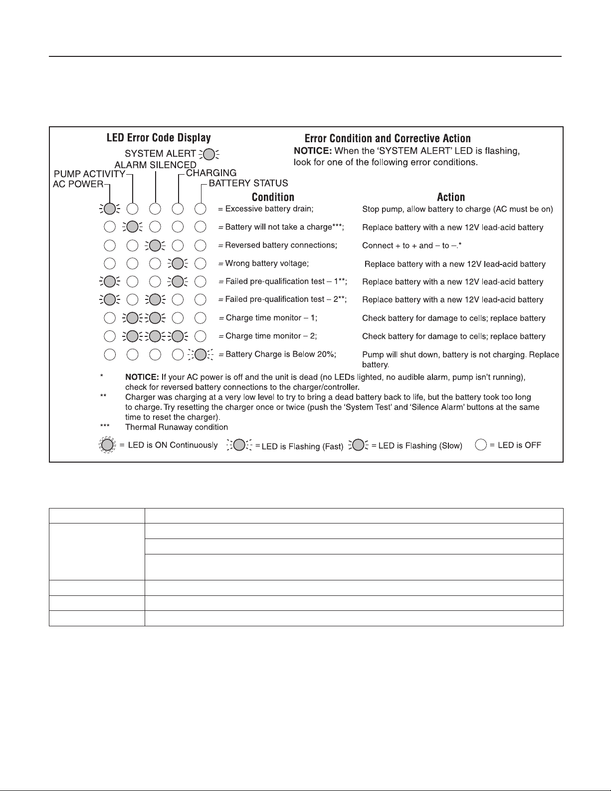
TABLE IV – Error Code Displays (LEDs Flashing)
TABLE V – Control Button Functions
Control Button: Result of Pushing Button:
System Test Pump starts and all LEDs light up.
Will reset the ‘PUMP ACTIVITY’ LED.
When pushed with the ‘SILENCE ALARM’ button, the Charger/Controller microprocessor resets
and error code resets.
Silence Alarm Toggle; Prevents the audible alarm sounding. Press and release to reset.
Light Toggles the light on the Charger/Controller on and off.
System Reset Press and release ‘TEST SYSTEM’ and ‘SILENCE ALARM’ to reset system.

Pump won’t run: Check all the wiring connections.
Check for a low or defective battery.
Check that the automatic switch is free to move up and down.
Press the circuit breaker reset button on the control panel.
Motor hums but pump won’t run: Check for low or defective battery.
Pump runs but pumps very little or no water: Make sure a check valve is installed and functioning between the
primary pump discharge and the Battery Backup wye.
Check for an obstruction in the discharge pipe.
The discharge pipe length and/or height exceeds the capacity of the
pump.
Check for a low or defective battery.
The Positive (+) and negative (–) pump wires are reversed.
Disconnect them and reconnect correctly.
Pump cycles too frequently: The check valve located between the discharge of the primary
pump and the Battery Backup wye is not installed or is not
working properly. Install an auxiliary check valve or replace the
existing check valve as required.
TROUBLESHOOTING - PUMP
Troubleshooting 15

Repair Parts 16
6982 0916
3
9
7
4
5
1
6
8 – Gateway Kit
2
10B
10C
10D 10F
10E
10B
10
10G
10A
Key No. Part Description Part Number
1DC Backup Pump PS17-2005*
21-1/4 FNPT x 1-1/2 Slip Elbow U78-1012
3Float Switch PS17-2003
4 Charger/Controller PS217-1522
5Battery Case Base
Battery Case Cover
PS17-2044
PS17-2045
6AC Adaptor PS17-2008
7Cable Ties - 11” **
8Gateway Kit (Gateway, Power Supply, 1m RJ45 Cable) U117-1568
9Switch Bracket PS17-2004
* If pump fails, replace entire system.
** Purchase at local hardware store.
NOTICE: All check valves must be installed as described in the installation instructions or the warranty is void. This
includes the check valve for the primary sump pump in a Common Discharge installation.
Part Description
Part
Number
AGM 75A-Hour BAT75
AGM 40A-Hour BAT40
Optional Battery Supplies
Sold Separately
Key Part Description Part Number
10 Hardware Replacement Kit (Includes Key Nos. 1A through 1G) PS198-270
10A Rubber Hose Coupling with Inserts (2) and Clamps (2) U74-68
10B 1-1/2 x 1-1/4 PVC Slip Reducer Bushing (2) †
10C PVC Tee 1-1/2 x 1-1/2 Slip x 1-1/4 FNP †
10D Auxiliary Check Valve †
10E 1-1/2 x 1-1/2 PVC Slip Coupling †
10F PVC Pipe Nipple, 1-1/4 NP x Close †
10G Check Valve Assembly, 1-1/4 FNP x 1-1/4 FNP †
†Included in Hardware Replacement Kit, Key No. 1.
NOTICE Key No. 10G Check Valve Assembly must be correctly installed or warranty is void. If primary sump pump has no check
valve installed below the Battery Backup Tee, Key No. 10D Auxiliary Check Valve must be correctly installed or warranty is void.

Optional Battery Supplies
Sold Separately
Warranty 17
Retain Original Receipt for Warranty Eligibility
Limited Warranty
This Limited Warranty is effective June 1, 2011 and replaces all undated warranties and warranties dated before June 1, 2011.
SIMER warrants to the original consumer purchaser (“Purchaser” or “You”) that its products are free from defects in material and
workmanship for a period of twelve (12) months from the date of the original consumer purchase. If, within twelve (12) months
from the original consumer purchase, any such product shall prove to be defective, it shall be repaired or replaced at SIMER’s
option, subject to the terms and conditions set forth herein. Note that this limited warranty applies to manufacturing defects only
and not to ordinary wear and tear. All mechanical devices need periodic parts and service to perform well. This limited warranty
does not cover repair when normal use has exhausted the life of a part or the equipment.
The original purchase receipt and product warranty information label are required to determine warranty eligibility. Eligibility
is based on purchase date of original product – not the date of replacement under warranty. The warranty is limited to repair or
replacement of original purchased product only, not replacement product (i.e. one warranty replacement allowed per purchase).
Purchaser pays all removal, installation, labor, shipping, and incidental charges.
For parts or troubleshooting assistance, DO NOT return product to your retail store. Contact SIMER Customer Service at
800-468-7867.
Claims made under this warranty shall be made by returning the product (except sewage pumps, see below) to the retail outlet
where it was purchased immediately after the discovery of any alleged defect. SIMER will subsequently take corrective action
as promptly as reasonably possible. No requests for service will be accepted if received more than 30 days after the warranty
expires. Warranty is not transferable and does not apply to products used in commercial/rentalapplications.
Sewage Pumps
DO NOT return a sewage pump (that has been installed) to your retail store. Contact SIMER Customer Service. Sewage pumps
that have seen service and been removed carry a contamination hazard with them.
If your sewage pump has failed:
• Wear rubber gloves when handling the pump;
• For warranty purposes, return the pump’s cord tag and original receipt of purchase to the retail store;
• Dispose of the pump according to local disposal ordinances.
Exceptions to the Twelve (12) Month Limited Warranty
Product Warranty Period
BW85P, M40P 90 days
2115, 2300, 2310, 2330, 2883, 2886, 2943, 2955, 2956, 2957, A5300, A5500 2 Years
4” Submersible Well Pumps, 2945, 2958, 2975PC, 3075SS, 3963, 3984, 3995,
4185, 4185P, 4186, 4188, 4190
3 Years
Pre-Charged Pressure Tanks, 3985, 3986, 3988, 3989, 5910, 5950, 5955, 5965, 5975 5 Years
General Terms and Conditions; Limitation of Remedies
You must pay all labor and shipping charges necessary to replace product covered by this warranty. This warranty does not
apply to the following: (1) acts of God; (2) products which, in SIMER’s sole judgement, have been subject to negligence, abuse,
accident, misapplication, tampering, or alteration; (3) failures due to improper installation, operation, maintenance or storage; (4)
atypical or unapproved application, use or service; (5)failures caused by corrosion, rust or other foreign materials in the system,
or operation at pressures in excess of recommended maximums.
This warranty sets forth SIMER’s sole obligation and purchaser’s exclusive remedy for defective products.
SIMER SHALL NOT BE LIABLE FOR ANY CONSEQUENTIAL, INCIDENTAL, OR CONTINGENT DAMAGES WHATSOEVER.
THE FOREGOING WARRANTIES ARE EXCLUSIVE AND IN LIEU OF ALL OTHER EXPRESS AND IMPLIED WARRANTIES,
INCLUDING BUT NOT LIMITED TO THE IMPLIED WARRANTIES OF MERCHANTABILITY AND FITNESS FOR A PARTICULAR
PURPOSE. THE FOREGOING WARRANTIES SHALL NOT EXTEND BEYOND THE DURATION PROVIDEDHEREIN.
Some states do not allow the exclusion or limitation of incidental or consequential damages or limitations on how long an
implied warranty lasts, so the above limitations or exclusions may not apply to You. This warranty gives You specific legal rights
and You may also have other rights which vary from state to state.
SIMER • 293 Wright Street • Delavan, WI U.S.A. 53115
Phone: 800-468-7867 • Fax: 800-390-5351 • www.simerpump.com

Sécurité 18
Consignes de sécurité importantes
CONSERVER CES DIRECTIVES - Ce manuel contient
des directives importantes devant être respectées lors de
l’installation, de l’utilisation et de l’entretien de ce produit.
Il s’agit du symbole d’alerte à la sécurité. Ce symbole,
lorsqu’il se trouve sur votre pompe ou votre manuel, signale
qu’il faut chercher la présence de l’un de ces mots indicateurs
et être conscient des risques de blessure!
indique un risque qui, s’il n’est pas évité, causera
des blessures graves, voire la mort.
indique un risque qui, s’il n’est pas évité, peut
causer des blessures graves, voire la mort.
indique un risque qui, s’il n’est pas évité, peut
causer des blessures mineures, voire modérées.
AVIS vise des pratiques qui ne concernent pas les blessures.
Lire soigneusement et respecter toutes les consignes de
sécurité contenues dans ce manuel ou placées sur la pompe.
Faire en sorte que les étiquettes de sécurité demeurent en
bon état. Remplacer les étiquettes de sécurité manquantes ou
endommagées.
Pour éviter tout risque de blessures graves causées par un
choc électrique ou des brûlures de même que tout risque de
dommage à cause d’une inondation, prendre le temps de bien
lire les consignes de sécurité avant d’installer la pompe.
L’acide de batterie est une matière corrosive.
Ne pas mettre en contact avec la peau, les vêtements ou le
chargeur de batterie. Porter une protection oculaire et à la tête
lorsqu’il est nécessaire de manipuler des batteries. Brancher et
débrancher les bornes de sortie CC uniquement après avoir
débranché le chargeur de la prise CA. Ne jamais laisser les
bornes CC se toucher.
Tension dangereuse. Peut causer des chocs
électriques graves, voire mortels. Ne pas brancher ou
débrancher le chargeur de batterie lorsque vous vous tenez sur
une surface mouillée ou inondée. S’assurer qu’une main
demeure libre au moment de brancher ou de débrancher le
chargeur. Si le plancher du sous-sol est mouillé, couper
l’alimentation électrique vers le sous-sol avant de marcher sur
le plancher.
Risque d’inondation. Ne pas faire fonctionner
la pompe à sec. Ce faisait, les joints de la pompe seront
endommagés, créant potentiellement une fuite et des
dommages à la propriété.
Suivre les consignes des codes de plomberie et d’électricité
locaux et nationaux au moment d’installer le système. Il est
recommandé d’utiliser un disjoncteur de fuite de terre (GFCI)
avec tout appareil électrique submergé dans l’eau.
N’utiliser ce système que comme pompe de puisard de secours
dans un milieu résidentiel. Il n’a pas été conçu pour servir de
pompe de puisard principale.
Ne pas soulever la pompe à partir de son cordon électrique.
Risque de choc électrique. Ne pas soulever la
pompe par son cordon électrique; plutôt, la soulever par le
tuyau de décharge, l’anneau de levage ou la poignée qui se
trouve dessus. Le cordon pourrait être endommagé s’il est
utilisé pour soulever la pompe.
Ne pomper que de l’eau propre avec cette pompe.
La pompe a été lubrifiée de manière permanente en usine. Ne
pas essayer de la lubrifier!
Garder le chargeur de batterie et le boîtier de batterie en
hauteur, dans un endroit sec, frais et bien aéré.
AVIS : si un détecteur de monoxyde de carbone (CO) est
installé, il doit se trouver à au moins 4,6 m (15 pi) du chargeur
de batterie, ce afin d’éviter l’occurrence de fausses alarmes. Se
reporter aux directives d’installation du détecteur de CO pour
en apprendre davantage.
Pour éviter les risques d’incendie ou d’explosion, assurer que
les sources d’étincelles ou de flammes (pilote) se trouvent à
l’écart de la batterie.
La distance de pompage verticale maximale de la pompe est de
4,3 m (14 pi), dans le cas du modèle A5300.
S’assurer qu’il n’y a pas de débris encombrant la pompe de
puisard. Les débris peuvent endommager la pompe et ainsi
entraîner une inondation.
Avertissement lié à la Proposition 65 de la Californie
Ce produit et les accessoires connexes
contiennent des produits chimiques reconnus dans l’État
de la Californie comme pouvant provoquer des cancers,
des anomalies congénitales ou d’autres dangers relatifs à la
reproduction.
RENSEIGNEMENTS GÉNÉRAUX
La pompe de puisard à batterie de secours ne peut pas se
substituer à votre pompe de puisard principale. Elle a été
conçue pour agir en tant que support pour votre pompe
principale en cas de panne d’électricité ou de tout autre
problème nuisant au fonctionnement normal de la pompe
primaire. Ne pas utiliser ce système pour pomper des liquides
inflammables ou des produits chimiques. Ne pomper que de
l’eau propre avec cette pompe.
Assurer que le chargeur de batterie demeure au sec et bien
protégé contre tout dommage.
Ce système a été conçu pour fonctionner avec une batterie
AGM (plomb-gel et feutre) scellée et sans entretien. Il peut aussi
fonctionner avec une batterie plomb-acide à électrolyte liquide
à décharge poussée. Les batteries à électrolyte gélifié et scellées
plomb-acide à électrolyte liquide ne sont pas recommandées.
En cas d’urgence (comme une panne de courant prolongée),
si la batterie à décharge poussée est complètement déchargée,
il est possible d’utiliser une batterie automobile à la place.
Prendre soins de remettre la batterie à décharge poussée en
place aussi rapidement que possible. Utiliser une batterie
automobile à la place d’une batterie à décharge poussée réduira
significativement la performance totale du système. Les batteries
automobiles ne sont pas conçues pour ce type d’application;
elles seront rapidement rendues inutiles par les cycles répétés de
charge/décharge. AVIS: ce système n’a pas été conçu pour les
applications impliquant l’eau salée, la saumure ou la présence
de poissons; l’utiliser dans ces conditions entraînera l’annulation
de la garantie!.

Installation 19
OUTILS DE BASE ET PIÈCES
NÉCESSAIRES (vendus séparément)
Pince multiprise à crémaillère ou autre pince réglable de
grande taille
Ruban à mesurer
Clé à douille ou tourne-écrou de 7,9 mm (5/16 po)
Couteau latéral
Scie à métaux (pour couper du tuyau de PVC)
Pinces de taille moyenne
Tournevis à lame plate
Tournevis cruciforme
Crayon ou marqueur
Ruban scellant pour filets de tuyau en PTFE
Colle pour PVC (soudure par solvant)
Nettoyant à tuyau de PVC
Chiffon
Raccords de plastique
Clapet(s) de non-retour - 1 ou 2, selon l’installation
Batterie à stockage de 38-120 ampères-heures ou à décharge
poussée
Capacité de batterie requise :
Pour obtenir de meilleurs résultats, se servir des batteries à
stockage AGM suivantes :
Pièce Amp-Heure
Gal/Charge à 3
m (10 pi)
Temps de
fonctionnement
approx
BAT40 40 4800 5 heures
BAT75 75 11500 11,5 heures
• Unité pouvant être équipée d’une batterie double
• Amp-heure maximum : 120
AVIS : Le chargeur ne parviendra pas à charger complètement
les batteries dont la cote d’ampères-heure est excessive sans
procéder à la réinitialisation du système.
SYSTÈME DE SECOURS À
BATTERIE (SSB) INSTALLATION ET
FONCTIONNEMENT
AVIS :
• Installer ce système à un moment où il n’est pas nécessaire
de faire fonctionner la pompe principale. Rassembler
tout le matériel nécessaire avant de commencer. Lire tous
les avertissements et les étapes d’installation avant de
commencer.
• Prendre en considération que l’eau pourrait couler des
raccords ou de la tuyauterie lors du démontage ou de la
coupe du tuyau de décharge. Protéger les composantes du
système, les outils et le matériel pour ne pas les mouiller.
Sécher la surface de travail à mesure qu’elle elle mouillée.
AVIS : lire attentivement les pages 4 à 6 pour déterminer la
méthode d’installation la plus appropriée. L’installation de type
« décharge distincte » (figure 2, page 4) est recommandée.
AVIS : vérifier les codes et les règlements locaux concernant
l’élimination des eaux usées (particulièrement lorsque la
pompe se décharge hors de la maison) avant de commencer.
L’installation doit se conformer à toutes les exigences légales.
Si possible, installer le SSB de manière à ce que la décharge soit
évacuée directement à l’extérieur (tuyau de décharge distinct
du tuyau de décharge de la pompe de puisard principale). Si
cette option n’est pas envisageable, passer à l’option « décharge
commune » (figure 3, page 4).
AVIS : Applicable pour TOUTES les installations une fois
terminées, il faut faire fonctionner en même temps les deux
pompes de puisard (la pompe principale et la pompe de
secours) pendant un cycle complet pour vérifier que tout
fonctionne correctement.
Risque de blessure et d’inondation. Ne pas mettre la
pompe en marche tant que tous les raccords n’ont pas été collés et que
la colle n’a pas eu le temps de sécher. Les raccords lâches peuvent
exploser et causer des blessures ou une inondation.
Risque de choc électrique. Sur le panneau électrique ou
la boîte de fusibles, couper l’alimentation électrique se rendant vers la
pompe de puisard avant de commencer l’installation.
Mise en place
1. Déterminer le niveau d’eau élevé dans le puits de puisard (le
niveau d’eau auquel la pompe de puisard en place (principale) se
met en marche - se reporter à la figure 1). Couper l’alimentation
vers la pompe et indiquer ce niveau sur le tuyau de décharge à
l’aide d’un crayon ou d’un marqueur.
2. Vider le puits de puisard aussi profondément que possible sans
que la pompe se mette à fonctionner à vide. Pour ce faire :
A. INTERRUPTEUR DE SORTIE CONJOINTE : débrancher
la pompe et l’interrupteur de la prise puis débrancher la
pompe de l’interrupteur de sortie conjointe. Réinitialiser le
disjoncteur de circuit ou remettre le fusible en place puis
brancher la pompe directement dans la prise. La pompe va
démarrer. Vidanger le puits et débrancher la pompe. OU
B. SANS INTERRUPTEUR DE SORTIE CONJOINTE : réinitialiser
le disjoncteur de circuit ou remettre le fusible en place et
se servir d’un manche à balai ou d’un bâton pour soulever
l’interrupteur à flotteur, ce qui devrait faire fonctionner la
pompe. Vidanger le puits puis relâcher l’interrupteur.
3. Une fois le puits vidangé, couper (ouvrir) le disjoncteur de circuit
ou enlever le fusible à nouveau pour éviter tout choc électrique
pendant l’installation.
'Turn on'
water level of
Primary Pump
Sump Pit
Check
Valve
Remove the
hose coupling
or mark the
1st cut here.
Support the pipe
before cutting.
3547 1016
Mark pipe with
pencil here
(2nd cut).
Fig 1 : faire une marque au niveau d’eau de «
démarrage »
Clapet de non
retour
Puits de puisard
Niveau de demarrage
de la pompe principlae
Débrancher
le raccord en
caoutchouc ou
repérer la première
coupe ici.
Supporter le tuyau
avant de le couper.

Installation 20
INSTALLATION FACILE – MÉTHODE A
La méthode installation facile recommandée suggère d’installer
les deux pompes sur le fond du puisard. Se reporter à la Figure
2. Le diamètre minimum requis du puisard à sa partie inférieure
et sa profondeur recommandée doivent être de 18 po.
Les autres fournitures dont on aura besoin seront 2 coudes à
90° de 1 1/4 po et 2 mamelons courts de 1 1/4 po.
Second Cut:
at Marked
Water Line
First Cut:
Backup Pump Installation
(Method A)
Not to Scale
Switches and
Wiring omitted
for clarity
1-1/2" x 1-1/4"
Reducer bushing
for 1-1/4" pipe
1-1/2" x 1-1/4"
Reducer bushing
for 1-1/4" pipe
Tee
1-1/2" x 1-1/2"
slip x 1-1/4" FNPT
Short Length
of Discharge Pipe
(may vary)
Primary Sump
Pump Check Valve
to prevent
recirculation
into the sump;
required if not
already installed
on pump
Cut-Off piece of
discharge pipe.
Hose Coupling
with Clamps
1-1/4" Elbow
1-1/4"
Elbow
Close
Pipe
Nipple
(1-1/4"
x 1-1/4")
Back-up Pump
Discharge Port
Primary Pump
Discharge Port
(1 Nipple
is included
with the
back-up
pump
package)
6977 0515
Check Valve
Assembly
Battery
Backup
Switch*
Figure 2 – Schéma de l’installation – Méthode A
1. Procéder à une deuxième coupe du tuyau de refoulement
au repère fait au crayon. Avec un chiffon propre, nettoyer
les extrémités du tuyau, puis mettre de côté le morceau de
tuyau de refoulement coupé.
2. Glisser un coude à 90° (à acheter localement) sur le
refoulement de la pompe de secours.
3. Enrouler les filets des 3 mamelons courts de deux tours
du ruban d’étanchéité en PTFE pour filetage (Réf. 3), puis
visser un mamelon sur le coude. Mettre les deux autres de
côté.
4. Revisser le clapet de non retour sur le mamelon court.
REMARQUE: S’assurer que le clapet de non retour est
installé dans le bon sens. Se reporter à l’encadré de la
Figure 3.
Elbow
Back-up Pump
Discharge
Tee
6978 0515
Check
Valve
Assembly
Close
Pipe
Nipple
(The valve
flap opens
away from the
pump outlet)
Water
Flow
through
valve
Check Valve
Primary
required if
not already
installed
on pump
Figure 3 - Installation à ajustement serré
5. Visser un mamelon court sur l’autre extrémité du clapet de
non retour.
6. Visser le deuxième coude à 90° sur le mamelon.
1 ¼ po NPT
7. Visser le dernier mamelon sur le coude.
8. Visser le té sur le mamelon, puis mettre cet ensemble de
côté.
9. Brancher une petite longueur de tuyau sur le clapet de non
retour du refoulement de la pompe principale. Se reporter
à la Figure 4.
REMARQUE: Un clapet de non retour doit être installé sur
ce tuyau de refoulement de la pompe principale, entre le
té et la pompe principale. Ceci empêchera la recirculation
dans la pompe principale lorsque la pompe de secours se
mettra en marche.
10. Glisser une bague de réduction (si requise) sur l’extrémité
du tuyau provenant du refoulement de la pompe
principale. Ne pas coller ce raccord pour le moment.
REMARQUE: Si le diamètre du tuyau de refoulement est
de 1 1/4 po, il faudra coller les bagues de réduction dans
le premier té, puis glisser le morceau coupé du tuyau de
refoulement dans la bague.
11. Glisser le té et le sous-ensemble de la patte de la pompe
de secours sur la bague de réduction.
12. Coller le morceau de tuyau coupé sur la bague de
réduction qui se trouve en haut du té.
13. Poser l’interrupteur à flotteur sur le tuyau de refoulement
avec les colliers, sans les serrer. Se reporter à la Figure 4.
Ne pas serrer les colliers. Il faudra peut-être procéder à des
réglages plus tard.
Pas à l’échelle
Les interrupteurs et
le câblage ne sont
pas montrés pour
plus de clarté.
Raccord en
caoutchouc et
colliers
Morceau coupé
du tuyau de
refoulement
Première coupe
Petite longueur de
tuyau de refoulement
(peut varier)
Clapet de non retour
de la pompe de puisard
principale; empêche
la recirculation dans le
puisard; requis si pas déjà
installé sur la pompe
Orifice de
refoulement de la
pompe principale
Mamelon
court
(1 1/4 po
x 1 1/4 po)
(1 mamelon
est livré
avec la
pompe de
secours)
Coude de
1 1/4 po
Orifice de
refoulement de la
pompe de secours
clapet de
non retour
coude de
1 1/4 po
Bague de
réduction de 1
1/2 po x 1 1/4
po pour tuyau
de 1 ¼ po
Té de 1 1/2 po x 1 1/2
po à glissement x 1 1/4
po FNPT
Bague de réduc-
tion de
1 1/2 po x 1 1/4
po pour tuyau
de 1 ¼ po
Interrupteur
de batterie de
secours*
Deuxième
coupe à la
ligne d’eau
repérée
Té Mamelon
court
Coude
Clapet de
non retour
L’eau
circule
dans le
clapet
(L’obturateur
du clapet de
non retour s’ouvre à
l’opposé du refoulement
de la pompe) Refoulement de la
pompe de secours
Clapet antiretour
primaire requis si
pas déjà installé
sur la pompe
Installation de la pompe de secours
(Méthode A)
Table of contents
Languages:
Popular Power Supply manuals by other brands

Rockwell Automation
Rockwell Automation Allen-Bradley 1606-XLE120EL installation instructions

VOLTCRAFT
VOLTCRAFT PLC-2400C operating instructions

Fisher Scientific
Fisher Scientific FB1000-2 Operator's manual

Sanela
Sanela SLZ 08 Mounting instructions

Optimal Power
Optimal Power OPR200-05S user manual

Et system
Et system LAB-SMS/E Series manual


