Oxford Instruments Shasta User manual

3900001 Rev. C Page 1 of 24
User Manual
Issue 02 / February 2015 / Shasta User Manual
Shasta High Voltage Power Supply
User Manual
Oxford Instruments
X-Ray Technology
Shasta 50/60 kV High Voltage Power Supply
Issue 02 /February 2015 /Shasta User Manual

3900001 Rev. C Page 2 of 24
User Manual
Issue 02 / February 2015 / Shasta User Manual
Shasta High Voltage Power Supply
IMPORTANT SAFETY PRECAUTIONS
GENERAL SAFETY PRECAUTIONS
This power supply generates voltages that are dangerous and may be fatal.
Please observe extreme caution when working with this equipment.
High voltage power supplies must always be grounded.
Do not touch the connections unless the equipment has been turned off and the capacitance of
both the load and power supply has been discharged.
Wait at least five minutes for the internal capacitance of the power supply to discharge.
Do not ground yourself or work under wet or damp conditions.
SERVICE SAFETY PRECAUTIONS
There are no user serviceable parts in the power supply.
Service should be performed by a trained Oxford Instruments technician.
DANGER: the product manual identifies hazards in the operation of this unit that could possibly
lead to injury or death.
CAUTION: the product manual identifies procedures to be followed to avoid possible damage to
the equipment.
The product manual can be downloaded at:
http://www.oxford-instruments.com/shasta-manual

3900001 Rev. C Page 3 of 24
User Manual
Issue 02 / February 2015 / Shasta User Manual
Shasta High Voltage Power Supply
WICHTIGE SICHERHEITSVORKEHRUNGEN
ALLGEMEINE SICHERHEITSVORKEHRUNGEN
Dieses Netzgerät erzeugt gefährliche Spannungen, die möglicherweise zum Tod führen
können.
Bitte seien Sie ausgesprochen vorsichtig, wenn Sie mit diesem Gerät arbeiten.
Hochspannungsnetzgeräte müssen immer geerdet sein.
Berühren Sie die Stecker des Netzgeräts nur, wenn das Gerät ausgeschaltet ist und sich die
elektrischen Kapazitäten der angeschlossenen Last und des Netzgeräts entladen haben.
Warten Sie mindestens fünf Minuten, bis sich die internen Kapazitäten des Netzteils entladen
haben.
Erden Sie sich nicht und arbeiten Sie nicht in einer nassen oder feuchten Umgebung.
SICHERHEITSVORKEHRUNGEN FÜR DIE WARTUNG
Die Wartung des Netzgeräts erfordert möglicherweise das Entfernen der Geräteabdeckung bei
eingeschaltetem Strom.
Die Wartung sollte von einem ausgebildeten Techniker durchgeführt werden, der die
elektrischen Gefahren kennt.
WARNHINWEISE: Im Produkthandbuch werden Gefahren beim Betrieb dieses Geräts genannt,
die möglicherweise zu Verletzungen oder zum Tod führen können.
VORSICHTSMASSREGELN: Im Produkthandbuch werden zu befolgende Vorgehensweisen
identifiziert, um mögliche Schäden am Gerät zu vermeiden.
Das Produkthandbuch kann unter folgender Adresse heruntergeladen werden:
http://www.oxford-instruments.com/shasta-manual

3900001 Rev. C Page 4 of 24
User Manual
Issue 02 / February 2015 / Shasta User Manual
Shasta High Voltage Power Supply
PRÉCAUTIONS DE SÉCURITÉ IMPORTANTES
PRÉCAUTIONS DE SÉCURITÉ GÉNÉRALES
L'alimentation génère des tensions dangereuses pouvant être mortelles.
Veuillez faire preuve d'une extrême prudence lorsque vous travaillez avec cet
équipement.
Les alimentations à haute tension doivent toujours être mises à la terre.
Ne touchez pas les connexions, sauf si l'équipement a été éteint et que la capacitance a été
déchargée pour la charge et l'alimentation.
Attendez au moins cinq minutes pour que la capacitance interne de l'alimentation se décharge.
Ne vous reliez pas à la terre et ne travaillez pas dans des conditions humides.
PRÉCAUTIONS DE SÉCURITÉ POUR L'ENTRETIEN
La maintenance de l'alimentation peut requérir le retrait du couvercle de l'instrument alors que
celui-ci est sous tension.
L'entretien doit être effectué par un technicien formé ayant connaissance des dangers
électriques.
AVERTISSEMENT : le manuel du produit identifie les risques lors de l'utilisation de cet appareil
pouvant potentiellement causer des dégâts ou la mort.
ATTENTION : le manuel du produit identifie les procédures à suivre pour éviter d'endommager
l'équipement.
Le manuel du produit est disponible au téléchargement à l'adresse suivante:
http://www.oxford-instruments.com/shasta-manual

3900001 Rev. C Page 5 of 24
User Manual
Issue 02 / February 2015 / Shasta User Manual
Shasta High Voltage Power Supply
IMPORTANTES PRECAUCIONES DE SEGURIDAD
PRECAUCIONES DE SEGURIDAD GENERALES
Esta fuente de alimentación genera voltajes peligrosos que podrían ser mortales.
Por favor tenga extremo cuidado cuando trabaje con este equipo.
Las fuentes de alimentación de alto voltaje siempre deben estar conectadas a tierra.
No toque las conexiones excepto que el equipo haya sido apagado y que la capacidad eléctrica
de la carga y de la fuente de alimentación hayan sido descargadas.
Espere al menos cinco minutos a que la capacidad eléctrica interna de la fuente de
alimentación se descargue.
No se ponga a masa ni trabaje en condiciones húmedas.
PRECAUCIONES DE SEGURIDAD DE MANTENIMIENTO
El mantenimiento de la fuente de alimentación podría requerir quitar la cubierta del instrumento
con la electricidad encendida.
El mantenimiento debe ser realizado por un técnico preparado que conozca los riesgos
eléctricos.
ADVERTENCIA: el manual del producto identifica riesgos en la operación de esta unidad que
podrían causar heridas e incluso la muerte.
PRECAUCIÓN: el manual del producto identifica procedimientos a seguir para evitar el daño
del equipo.
El manual del producto puede descargarse en:
http://www.oxford-instruments.com/shasta-manual

3900001 Rev. C Page 6 of 24
User Manual
Issue 02 / February 2015 / Shasta User Manual
Shasta High Voltage Power Supply
重要的安全注意事项
一般安全注意事项
此电源产生的高电压非常危险,甚至致命。
使用此设备时请格外小心。
高压电源必须始终接地。
不要接触连接器,除非设备电源已关闭,负载和电源内部的电容已完全放电。
至少等待 5 分钟,让电源的内部电容充分放电。
不要让自己接地,也不要在潮湿的环境下操作。
维护时的安全注意事项
维护电源时可能需要带电取下设备盖。
维护工作应当由知晓电气危害的专业技术人员执行。
警告:产品手册列出了操作此设备时出现的可能导致伤害或死亡的危害。
注意:产品手册列出了应当严格遵守的操作流程,以避免可能对设备造成的损坏。
产品手册可以从以下地址下载:
http://www.oxford-instruments.com/shasta-manual

3900001 Rev. C Page 7 of 24
User Manual
Issue 02 / February 2015 / Shasta User Manual
Shasta High Voltage Power Supply
Table of Contents
Introduction
Shasta Power Supply Overview
Shasta Models
Description
Interface
Safety and Reliability
Safety Guidelines
Regulatory Compliance
Quality Management System
Reliability
EMC
Environment
Electrical Performance
Input Power
High Voltage Output
Filament Output
Grid Voltage Output
Grounding
Protection
Control of the High Voltage Power Supply
Analog Control Overview
Interlock
Setting kV and mA Set Points
Local Control Setting
Remote Setting Control
Setting Grid Bias Scaling (Optional Feature)
Setting the Grid Bias Voltage
Filament Current Limit
Adjusting Filament Current –Off Tube

3900001 Rev. C Page 8 of 24
User Manual
Issue 02 / February 2015 / Shasta User Manual
Shasta High Voltage Power Supply
Adjusting Filament Current –On Tube
Basic Steps to X-ray Generation –Analog Control
Monitoring X-rays
LED Indicators
Electrical Connections
J1 High Voltage Output & J3 Filament/Grid Connector (3 Pin)
J2 DC Power Connector (2 Way)
J4 Monitor/Interlock Connector (4 Way)
J5 Programming Connector (9 Way)
Mechanical Outline
Input Connection Diagram
Outline Drawing
Safety Ground Connection
Maintenance
Replacement of components (including fuses)
Replacement of consumables, routine maintenance of parts
Cleaning
Repairs

3900001 Rev. C Page 9 of 24
User Manual
Issue 02 / February 2015 / Shasta User Manual
Shasta High Voltage Power Supply
Introduction
This document provides the information required to operate the Shasta series power supplies safely and
within the limits of the specification. It must be read in full before any attempt is made to operate the
power supply.

3900001 Rev. C Page 10 of 24
User Manual
Issue 02 / February 2015 / Shasta User Manual
Shasta High Voltage Power Supply
Shasta Power Supply Overview
The Shasta power supply series is designed to be used as a grounded cathode X-ray tube power driver.
It contains the power supply stages (HV, filament and optional grid) and the control circuitry necessary to
the supply and control of an X-ray tube.
Shasta Models
Model Power Voltage Filament Grid/Bias
9700001 50W Power +50kV Voltage +5V 3.5A Filament N/A
9700002 50W Power +50kV Voltage +5V 3.5A Filament -300V
9700003 60W Power +60kV Voltage +5V 3.5A Filament N/A
9700004 60W Power +60kV Voltage +5V 3.5A Filament -300V
Description
The Shasta unit is supplied from a 24Vdc rail and delivers the following outputs via three separated
power stages:
A high voltage output for the supply of the X-ray tube anode. The high voltage can supply up to
+50kV or +60kV (depending on the model) with a maximum output current of 1mA
A low voltage output for the supply of the X-ray tube filament. The filament current can supply up
to 3.5A. The maximum output voltage is +5V
An optional grid bias output with -300V 0.25mA, the grid bias is automatically increased with the
high voltage. The maximum scaling of the grid bias is adjustable
Interface
The analog interface offers the following functionalities via connectors and potentiometers located on the
front panel:
Input power Interlock
Control of the high voltage via a 0 to 10V analog input or an internal multi turn potentiometer
Control of the beam current via a 0 to 10V analog input or an internal multi turn potentiometer
(The control of the beam current is obtained via the filament loop)
Limitation of the maximum filament current is via an internal multi turn potentiometer (This sets a
limit to the filament loop current demand)
Analog outputs for the monitoring of high voltage and beam current

3900001 Rev. C Page 11 of 24
User Manual
Issue 02 / February 2015 / Shasta User Manual
Shasta High Voltage Power Supply
Safety and Reliability
This power supply is intended for indoor professional use only in a non explosive and non corrosive
environment. It is capable of producing hazardous voltages and so must be treated with respect.
The product complies with the requirements of the Low Voltage Directive 2006/95/EC by complying with
EN61010 and is CE marked accordingly. To ensure safety in its final application the power supply must
be professionally installed into a final product and used in accordance with appropriate safety standards,
e.g., EN60950 or EN61010.
To maintain continued safety of the product and to the operator it is important that the entire handbook is
read carefully, paying particular attention to the safety guidelines presented in this section. The
handbook should be read before attempting installation or operation of the power supply.
If you do not fully understand the information given in the handbook do not use the power supply.
Contact Oxford Instruments or an authorized agent for advice.
Safety Guidelines
This power supply is capable of producing hazardous voltages, which under some circumstances may
be fatal.
1) It is recommended that the power supply is only operated by personnel who are familiar with high
voltage and recognize the dangers it can pose.
2) The power supply 0V is common to the +24VDC input GND, the user interface and the
enclosure.
3) Connection of the power supply input, outputs and remote interface cables must be made in the
following order:
a) Ensure the power supply is disconnected from the supply.
b) Before touching the high voltage cable, ensure that the high voltage circuit and load are
discharged.
c) Connect the earth terminal to a protective earth.
d) Connect the user programming connector J5, monitor and interlock connector J4, ensure
the interlock is OFF.
e) Connect the filament cable (and Grid Bias if fitted) to J3
f) Connect the high voltage cable to J1 and to the load circuit.
g) Connect the de-energized supply to J2 using the input power cable, ensuring that the
earth terminal is securely connected to a protective earth.
h) Energize the supply and close the interlock as required.
4) Before removing or touching the high voltage output ensure that the input supply is de-energized
and all high voltage parts are fully discharged.
5) The input power cable (J2) and user interface (J4 and J5) must be disconnected before
disconnection of the earth terminal.
6) Where fitted the external inhibit command is purely functional and must not be considered or
used as a safety feature.
7) The output high voltage cable and load must not be accessible to the user. Ensure the equipment
enclosure housing the power supply has suitable interlocks to prevent contact with the high

3900001 Rev. C Page 12 of 24
User Manual
Issue 02 / February 2015 / Shasta User Manual
Shasta High Voltage Power Supply
voltage. Ensure that the creepage and clearance distances between the high voltage output and
the enclosure meet the requirements of a suitable safety standard, e.g., EN60950 or EN61010.
8) The power supply should only be operated with the HV output cable connected.
9) Ensure adequate ventilation of the power supply to ensure that possible ozone build up will be
kept to a safe level.
10)There are no user serviceable parts in the power supply. If the power supply fails to operate, it
must be returned to Oxford Instruments or to an Oxford Instruments authorized service center for
repair.
11)Do not use the power supply if it is damaged. Return to Oxford Instruments, or to an Oxford
Instruments authorized service center for examination.
12)The power supply should only be used for the purpose for which it is designed and manufactured.
Failure to do this may impair the protection provided by the power supply.
Regulatory Compliance
Meets the requirements of IEC61010-1:2010, EN61010-1:2010, UL61010-1:2012 and CAN/CSA C22.2
No. 61010-1:2012. The product carries the TUV SUD c/us mark.
By complying with BS EN61010-1:2010 it meets the requirements of the Low Voltage Directive (LVD),
2006/95/EC when it is installed as a component part of other equipment. It is CE Marked accordingly.
An M5 earth terminal is provided for a protective earth, this shall be connected to a safety earth at all
times when the unit is operational.
The input power shall be removed from the unit before removal of any covers or working on the HV unit.
Quality Management System
Oxford Instruments X-Ray Technology is certified to ISO 9001:2008.
Reliability
Mean time between failures (MTBF) is greater than 40000 hours in accordance with MIL-HDBK-217E.
EMC
The Shasta power supply is intended for installation as part of a system. Basic EMC filtering is provided.
The EMC performance of the power supply can only be assessed when it is installed within and as part
of the final system.

3900001 Rev. C Page 13 of 24
User Manual
Issue 02 / February 2015 / Shasta User Manual
Shasta High Voltage Power Supply
Environment
Temperature: 0 to +45ºC max case temperature (Operational)
-20 to +85ºC (Storage)
Humidity: 80% maximum relative humidity up to 31ºC, reducing
linearly to 50% at 40ºC, Non-condensing
Altitude: Sea level to 2000m
Electrical Performance
Input Power
Input voltage: 24Vdc +/-10%
Input Power: 100W, max
Protection: Reverse diode and internal series 7A fuse
High Voltage Output
Type: Voltage source
Voltage: +50kV max, 50W max, Specification applies above 5kV
Polarity: Positive
Ripple voltage: <100V peak to peak
Load regulation: Voltage: <0.01% for a 50% of max load variation,
Beam current: < ±2uA
Line regulation: For a 10% change in input voltage at rated output power
Voltage: <0.01%
Beam current: < ±2uA
Temperature coefficient: 100ppm/C over operating temperature range. Applies to voltage control,
current control, voltage monitor, and current monitor
Stability: +/-0.1% over an 8 hour period after 30 minutes warm-up
Filament Output
Type: Current source
Output Voltage: +5V
Output Current: 3.5A
Ripple voltage: <50mVpp over the whole operating range

3900001 Rev. C Page 14 of 24
User Manual
Issue 02 / February 2015 / Shasta User Manual
Shasta High Voltage Power Supply
Grid Voltage Output
Type: Voltage source
Voltage: -300V
Output Current: 0.25mA, (short circuit current 2-4mA)
Polarity: Negative
Ripple voltage: <300mV peak to peak
Load regulation: <2%, 10kΩ Output Impedance
Line regulation: <0.2% for a 10% change in input voltage at rated output load
Temperature coefficient: 300ppm/C over operating temperature range
Stability: +/-0.5% over an 8 hour period after 30 minutes warm-up
Control: The Grid bias is automatically adjusted by the kV output voltage
kV = 0, Grid bias = 0 and kV = +50kV Grid bias = maximum setting
Please note that the full scale Grid bias voltage is set by the front panel
mounted ‘Bias Adj’ potentiometer
Grounding
The system is designed to be used with a grounded cathode X-ray tube.
No isolation is provided between input and outputs, Ground (zero volts) is common to input and outputs.
Protection
The HV power supply is protected against short circuits of any duration and intermittent arcs.
The filament is protected against open circuit by a dedicated voltage control loop; it is also protected
from continuous short circuits and intermittent arcs.
Control of the High Voltage Power Supply
Analog Control Overview
Analog Control involves setting the kV and uA set points, adjusting the grid voltage (where applicable),
turning on/off x-rays and monitoring x-ray levels and fault conditions. The analog inputs can be set
either with the potentiometers located in the front panel, or by a remote voltage controller.
The filament current limit can also be adjusted, but in most cases the factory default setting should be
maintained.
Interlock
An interlock circuit is implemented that interrupts the supply to the high voltage power stage when open.
When the interlock circuit is open the high voltage and filament are turned off.
Connect pin 4 of J4 ‘INTLK’ to either a 12V 0.5W lamp or a 330R 1W resistor to the front panel earth
stud to close the interlock.
NOTE: Do not connect the ‘INTLK’ pin directly to 0V or the chassis, the unit will be
damaged if this is done as it uses a 12V internal relay.
Once the interlock is closed, the HV output and filament will be ramped up over a period of 4-6 seconds
to the demanded values.

3900001 Rev. C Page 15 of 24
User Manual
Issue 02 / February 2015 / Shasta User Manual
Shasta High Voltage Power Supply
Setting kV and mA Set Points
The kV and mA set points are set by providing an analog voltage to the ‘kV Prog’ and ‘mA Prog’ inputs.
The input range for these analog inputs is 0.0V to 10.0V.
NOTE: The Shasta supply provides a stable +10.0V reference on pin 1 of J5 that can be
used as the high end for the host’s analog outputs. Use of this reference voltage is
recommended, but not required.
For kV Prog, 0.0V corresponds to 0 kV, 10.0V corresponds to 50kV for 50kV models and 60kV for 60kV
models, Accuracy 1%
For mA Prog, 0.0V corresponds to 0 mA and 10.0V corresponds to 1.0 mA, Accuracy 1%
NOTE: For proper operation, the PROGRAM inputs must be low noise, with a peak to peak
noise of less than five millivolts. Noisy input signals will result in unstable X-ray flux.
Local Control Setting
The local control may be set by using the ‘kV Adj’ and ‘mA Adj’ potentiometers on the front panel of the
unit.
Connect pins 3 and 4 of J5 together, adjust the ‘kV Local’ potentiometer while monitoring pin 3 of
J5 ‘kV Prog Input’ to set the output voltage
Connect pins 6 and 7 of J5 together, adjust the ‘mA Local’ potentiometer while monitoring pin 6 of
J5 ‘mA Prog Input’ to set the output voltage
Remote Setting Control
The remote control may be set by applying positive voltages to the ‘kV Prog Input’ and ‘mA Prog Input’
pins. In this case, the ‘kV Local’ and ‘mA Local’ potentiometers are not used.
Apply a positive voltage on pin 3 of J5 ‘kV Prog Input’, the negative of the applied voltage should
be connected to pin 9 of J5 ‘GND’
Apply a positive voltage on pin 6 of J5 ‘mA Prog Input’, the negative of the applied voltage should
be connected to pin 9 of J5 ‘GND’

3900001 Rev. C Page 16 of 24
User Manual
Issue 02 / February 2015 / Shasta User Manual
Shasta High Voltage Power Supply
Setting Grid Bias Scaling (Optional Feature)
The grid bias scaling, available only on the 9700002 and 9700004 models, can be adjusted locally using
the ‘Bias Adj’ potentiometer on the front of the unit.
Setting the Grid Bias Voltage
1. Ensure the output voltage is set to 0kV, the unit is powered off, the HV cable is disconnected
from the power supply, and the HV well is covered with the red shipping cap.
2. Turn on the unit, and adjust the output voltage to 50kV.
3. Adjust the Grid Bias via the ‘Bias Adj’ potentiometer on the front of the unit to the optimal value
provided by Oxford Instruments (see note below). The Grid Bias may be measured directly
between J2 pin 3 (Grid Bias) and J3 pin 2 (Filament Return).
4. Adjust the output voltage back to 0kV. The Grid Bias will decrease linearly as the kV drops.
5. Power off the unit, then reconnect the cables and operate the tube normally.
NOTE: The optimal grid bias setting will vary from X-ray tube to X-ray tube. Please refer to
the documentation provided with the X-ray tube from Oxford Instruments for the optimal
grid bias setting.
CAUTION: The grid bias output can reach up to -300V. Ensure that appropriately rated
meters and cables (High impedance meter, 500VDC minimum voltage rating on meter and
test probes) are used to measure the grid voltage during programming.
Filament Current Limit
The filament current limit is a feature designed to protect the X-ray tube filament from overheating. By
default, this is set at the factory to 1.7A. It is recommended that this value not be changed by the
customer; however, instructions on how to change the filament current can be found below if it is
required by the application.
Adjusting Filament Current –Off Tube
1. Completely disconnect the X-Ray tube from the power supply
2. Place a Multimeter set to a current range greater than 4A directly across the filament output
connections J3 pins 1 and 2
3. Demand an output voltage of 500V and a beam current of maximum
4. Apply the 24Vdc to the power supply and close the interlock
5. Adjust the front panel ‘Fil Limit’ potentiometer to set the desired maximum filament current
Adjusting Filament Current –On Tube
1. Ensure that the 24Vdc is turned off
2. Adjust the front panel ‘Fil Limit’ to 0 by turning fully counter-clockwise (this may need up to 20
turns)
3. Demand the required output voltage and beam current
4. Apply the 24Vdc to the power supply and close the interlock
5. Adjust the front panel ‘Fil Limit’ clockwise to increase the maximum filament current while
monitoring the beam current monitor, stop adjusting when the required beam current has been
achieved

3900001 Rev. C Page 17 of 24
User Manual
Issue 02 / February 2015 / Shasta User Manual
Shasta High Voltage Power Supply
Basic Steps to X-ray Generation –Analog Control
1. Using either the local or remote programming options, set the kV and mA set points to the
desired set point
2. Close the interlock, enabling X-rays
3. Turn off x-ray generation by either opening the interlock or setting the kV and mA set points to 0
Monitoring X-rays
The Shasta power supply status can be monitored using the J4 and J5 connectors, as specified below:
Monitor Return/GND/0V: J4 pin 1
HV monitor: J4 pin 2 0V to +10V for 0kV to +50kV for 50kV models
0V to +10V for 0kV to +60kV for 60kV models
Accuracy ±1%
Output impedance 1kΩ
Beam current monitor: J4 pin 3 0V to +10V for 0mA to 1.0mA
Accuracy ±1%
Output impedance 1kΩ
Interlock Monitor: J5 pin 5 Open collector transistor, on when interlock closed.
No internal pull-up.
Output impedance 100Ω
Clamped to 26V, 100mA maximum
Filament current monitor: J5 pin 8 0V to 10V for 0A to 3.5A
Accuracy ±2%
Output impedance 1kΩ
LED Indicators
In addition to the connector outputs, the Shasta power supply has three LEDs which can be used to
visually identify the state of the supply:
Green LED Illuminated when +24V Input Power applied to unit
Yellow LED Illuminated when +24V Input Power applied to unit and Interlock is open
Red LED Illuminated when +24V Input Power applied to unit and Interlock is closed and HV can be
produced

3900001 Rev. C Page 18 of 24
User Manual
Issue 02 / February 2015 / Shasta User Manual
Shasta High Voltage Power Supply
Electrical Connections
J1 High Voltage Output & J3 Filament/Grid Connector (3 Pin)
The high voltage, filament and grid connections are made with custom cable assemblies, provided with
the power supply. These are available in a variety of lengths and configurations, depending on the
application requirement and type of X-ray tube being driven. The possible options are below:
Part Number
Description
9200008
Shasta Standard HV Cable, 1m
9200009
Shasta Standard HV Cable, 2m
9200010
Shasta Standard HV Cable, 3m
9200011
Shasta Apogee HV Cable, 1m
9200012
Shasta Apogee HV Cable, 2m
9200013
Shasta Apogee HV Cable, 3m
PIN
NAME
IN/OUT
FUNCTION
J3.1
FILAMENT
Output
Grounded filament positive output
J3.2
FILAMENT RETURN
Output
Grounded filament negative output
J3.3
GRID BIAS(OPTIONAL)
Output
Optional grid bias output
J2 DC Power Connector (2 Way)
Fitted to unit: PTR/Phoenix STLZ950/2-G-5.08-H-Green
Customer part: PTR/Phoenix AKZ950/2-5.08-Green (Supplied with unit)
PIN
NAME
IN/OUT
FUNCTION
1
+24V DC INPUT
Input
Main supply +24V DC
2
GND
Input
Main supply 0V
J4 Monitor/Interlock Connector (4 Way)
Fitted to unit: PTR/Phoenix STLZ950/4-G-5.08-H-Green
Customer part: PTR/Phoenix AKZ950/4-5.08-Green (Supplied with unit)
PIN
NAME
IN/OUT
FUNCTION
1
MONITOR RET/GND
Output
Return/ground for all monitor measurements
2
kV MONITOR
Output
High voltage kV monitor
3
mA MONITOR
Output
Beam current monitor
4
INTLK
Output
Interlock control connection

3900001 Rev. C Page 19 of 24
User Manual
Issue 02 / February 2015 / Shasta User Manual
Shasta High Voltage Power Supply
J5 Programming Connector (9 Way)
PIN
NAME
IN/OUT
FUNCTION
1
+10V DC REF
Output
+10V DC reference for programming
2
N/C
Unused pin. Should be left floating
3
kV PROG
Input
High voltage program input
4
kV LOCAL
Output
Output from the internal kV local program
potentiometer
5
INTERLOCK MONITOR
Output
Signal to show interlock status
6
mA PROG
Input
Beam current program input
7
mA LOCAL
Output
Output from the internal mA local program
potentiometer
8
FIL I MON
Output
Filament current monitor
9
0V/GROUND/RETURN
0V/Ground/Return for all analog program and
monitor signals

3900001 Rev. C Page 20 of 24
User Manual
Issue 02 / February 2015 / Shasta User Manual
Shasta High Voltage Power Supply
Mechanical Outline
Construction: Fabricated alloy with protective treatment
Grounding: Case and screen of output cable internally connected to 0V and chassis grounding
terminal
Cooling: Cooling of the power supply is by the conduction through the mounting panel
(case) and natural convection through the holes in the lid, one side panel and the
rear panel. Ensure that these are kept free of obstructions (or a minimum of 25mm
of clear space around these panels must be provided).
The ambient air temperature in the locality of the power supply should not exceed
45ºC and the case temperature of the power supply should not be allowed to
exceed 60ºC.
Size: Height: 140mm Width: 83.5mm Length: 240mm
Weight: 4kg (estimate)
Table of contents
Other Oxford Instruments Power Supply manuals
Popular Power Supply manuals by other brands

GRAUPNER
GRAUPNER SWITCHING POWER SUPPLY 13.8V 0-40A manual

Green Cubes
Green Cubes UNIPOWER M44 instruction manual
nextys
nextys NPSM240 Series instruction manual

SilverStone
SilverStone SST-SX500-LG Installation & optimization guide
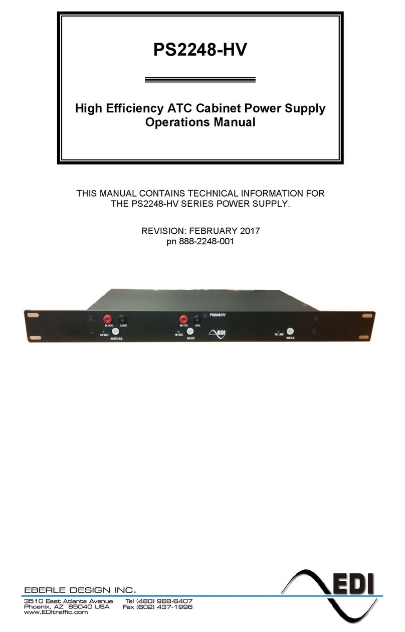
Eberle Design
Eberle Design PS2248-HV Operation manual
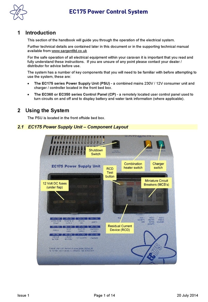
Sargent
Sargent EC175 Series manual
