Simfer T8630SM User manual
COOKER HOOD
SERVICE MANUAL

Contents
1.SAFETY INSTRUCTIONS............................................................................................................ 5
2. INTRODUCTION OF THE HOOD AND TECHNICAL DRAWINGS ............................................. 7
2.1. Technical Tables...................................................................................................................7
2.2. Drawings of the Appliance .................................................................................................... 9
2.2.1. T8630SM / T8631SM / T8632SM / T8731SM /T8930SM / T8931SM / T8932SM .......... 9
2.2.2. T8633SM / T8634SM / T8933SM / T8934SM / T8635SM /T8935SM / T8636SM /
T8936SM / T8638SM / T8938SM /T8670SM / T8671SM / T8652SM / T8952SM ....................9
2.2.3. T8639SM / T8939SM / T8640SM / T8940SM / T8649SM / T8949SM / T8650SM /
T8950SM / T8658SM / T8668SM / T8645SM / T8945SM / T8646SM / T8946SM /T7639SM /
T8651SM / T8653SM / T8655SM / T8656SM / T8673SM ......................................................10
2.2.4. T8643SM / T8644SM / T8743SM / T8743SM / T8744SM / T8641SM / T8642SM ....... 10
2.2.5. T8954SM / T8956SM (Island Type) ............................................................................. 11
3. INSTALLATION OF THE HOOD ...............................................................................................11
3.1.INSTALLATION OF HOOD MODELS T8630SM / T8631SM / T8632SM / T8731SM
/T8930SM / T8931SM / T8932SM .............................................................................................11
Installation of the Hanger Plate to the Hood ...........................................................................12
Installation of the Hanger Plate to the Wall.............................................................................12
Installation of the Inner Flue Hanger Plate..............................................................................12
Hanging the Hood to the Wall.................................................................................................13
Bringing the Hood to a Parallel Position to the Ground...........................................................13
Installation of the Aluminium Pipe...........................................................................................13
3.2. INSTALLATION OF HOOD MODELS T8633SM / T8634SM / T8933SM / T8934SM /
T8635SM /T8935SM / T8636SM / T8936SM / T8638SM / T8938SM /T8670SM / T8671SM /
T8652SM / T8952SM 15
Installation of the Hanger Plate to the Hood ...........................................................................15
Installation of the Hanger Plate to the Wall.............................................................................15
Installation of the Inner Flue Hanger Plate..............................................................................16
Hanging the Hood to the Wall.................................................................................................16
Bringing the Hood to a Parallel Position to the Ground...........................................................16
Installation of the Aluminium Pipe...........................................................................................17
3.3. INSTALLATION OF HOOD MODELS T8639SM / T8939SM / T8640SM / T8940SM /
T8649SM / T8949SM / T8650SM / T8950SM / T8658SM / T8668SM / T8645SM / T8945SM /
T8646SM / T8946SM /T7639SM / T8651SM / T8653SM / T8655SM / T8656SM / T8673SM ...18
Installation of the Hanger Plate to the Hood ...........................................................................19
Installation of the Hanger Plate to the Wall.............................................................................19
Installation of the Inner Flue Hanger Plate..............................................................................19
Hanging the Hood to the Wall.................................................................................................19

Bringing the Hood to a Parallel Position to the Ground...........................................................20
Installation of the Aluminium Pipe ..........................................................................................20
3.4. INSTALLATION OF HOOD MODELS T8643SM / T8644SM / T8743SM / T8743SM /
T8744SM / T8641SM / T8642SM .............................................................................................21
Installation of the Hanger Plate to the Hood...........................................................................22
Installation of the Hanger Plate to the Wall.............................................................................22
Installation of the Inner Flue Hanger Plate .............................................................................22
Hanging the Hood to the Wall.................................................................................................22
Bringing the Hood to a Parallel Position to the Ground...........................................................23
Installation of the Aluminium Pipe ..........................................................................................23
3.5. INSTALLATION OF HOOD MODELS T8954SM / T8956SM (Island Type) .......................25
Preparation of the Hood Upper Assembly..............................................................................25
Installation of the Hood Upper Assembly to the Ceiling..........................................................26
Installation of the Motor Box...................................................................................................27
Installation of the Aluminium Pipe ..........................................................................................27
Installation of the Outer Flue ..................................................................................................29
4. FUNCTIONS OF THE HOOD...................................................................................................31
4.1. CONTROL PANEL AND FUNCTIONS ...............................................................................31
FUNCTION/PRODUCT GROUP CHART...............................................................................31
Touch Control (applicable models): .......................................................................................32
Digital Control (applicable models): .......................................................................................32
Symbols and Functions: ........................................................................................................32
Push Button: (applicable models) ..........................................................................................32
Push Pull (applicable models): ..............................................................................................33
Operation of the Hood............................................................................................................33
Operation with Flue................................................................................................................33
Round Carbon Filter...............................................................................................................34
Usage of the Carbon Filter.....................................................................................................34
Installation of the Carbon Filter...............................................................................................34
Usage of the Aluminium Cassette Filter .................................................................................34
5. MAINTENANCE AND CLEANING OF THE HOOD...................................................................35
6.INSTALLATION / REMOVAL OF THE COMPONENTS.............................................................36
6.1.INSTALLATION...................................................................................................................37
6.2. REMOVAL..........................................................................................................................41
6.2.1. Removal of the Oil Filter ..............................................................................................41

6.2.2. Removal of the Lamp ..................................................................................................42
6.3. REMOVAL AND REINSTALLATION...................................................................................43
6.3.1. Removal of the Lamp ..................................................................................................43
7. CIRCUIT DIAGRAMS ...............................................................................................................48
With Candle Lamp, Push Button Control ...................................................................................48
With LED Lamp (2 pieces), Touch Control ................................................................................49
With LED Lamp (3 pieces), Touch Control ................................................................................50
With LED Lamp (4 pieces), Touch Control ................................................................................51
8. EXPLODED VIEW / SPARE PART LIST...................................................................................52
T8630SM /T8631SM /T8632SM / T8731SM /T8930SM / T8931SM / T8932SM ........................52
T8633SM / T8634SM / T8933SM / T8934SM / T8635SM / T8935SM / T8636SM / T8936SM /
T8638SM / T8938SM /T8670SM / T8671SM / T8652SM / T8952SM ........................................55
T8639SM / T8939SM / T8640SM / T8940SM / T8649SM / T8949SM / T8650SM / T8950SM /
T8658SM / T8668SM / T8645SM / T8945SM / T8646SM / T8946SM / T7639SM / T8651SM /
T8653SM / T8655SM / T8656SM / T8673SM ..........................................................................58
T8643SM / T8644SM / T8743SM / T8743SM / T8744SM / T8641SM / T8642SM .....................61
T8954SM / T8956SM (Island Type Hoods) ...............................................................................64

1.SAFETY INSTRUCTIONS
•This product is designed for home use.
•Operating voltage of the product is 220-240 Volt at 50Hz.
•Power cord of the appliance is grounded. This cord shall always be
connected to a grounded socket.
•The whole electrical wiring must be installed by a qualified electrician.
•Installation by unauthorized persons could lead to poor operation performance,
damage to the product, and accidents.
•The power supply cable shall not be stuck in any place or run over during
the installation process.
•The power cord shall not be routed near cookers, etc.; otherwise, it could
melt and cause a fire.
•Do not plug in the appliance before the installation.
•Make sure that the installation location allows the user to easily
unplug the power cord in case of any danger.
•Do not touch the lamps of the appliance when it is operated for a long time.
Since the lamps shall be hot, they may burn your hand.
•The kitchen cooker hoods intended for household use have been produced
for normal cooking practices. When used for other purposes, a failure risk
arises, and the appliance becomes out of warranty coverage.
•Comply with the rules and instructions for the discharge of exhaust air,
stipulated by the relevant authorities (This warning does not apply to uses
without flue).
•Flammable foods must not be cooked under the appliance.
•Switch the appliance on after placing saucepan, pan, etc. on the cooker.
Otherwise, high temperature may cause deformation of some parts of the
appliance.
•Turn off the cooker's burner before taking the saucepan, pan, etc. off the
cooker.
•Do not leave hot oil on the cooker. Pots that contain boiling oil may catch fire
by itself.
•Since oils could catch fire when you cooking fried foods in particular, be
careful about your curtains and tablecloths.
•Ensure that the filters are replaced within the specified periods. Filters not
replaced in a timely manner pose risk of fire due to accumulated grease
deposits on them.
•Do not use non-fire-resistant filtering materials instead of the filter.
•Since the packaging materials may be dangerous, they shall be kept them
away from children.

•Do not operate your appliance without filter, and do not remove
the filters when the appliance is being operated.
•In case of any flames, cut off power to the cooker hood and cooking
appliances. Cover the flames with a damp cloth or towel. Never use
water to extinguish the fire.
•If your product's periodic cleaning is not performed in a timely
manner, it could pose risk of fire.
•Cut off power supply to the appliance before maintenance
operations (by unplugging it).
•Use pipes with a diameter of 150mm or 120 mm while performing
the flue connection of the appliance. The length of the pipe
connection as well as the number of elbows must be as minimum
as possible.
•Make sure that the children does not play with the appliance. Do not
allow little children to operate the appliance.
•If the power supply cable is damaged, it shall be replaced by its
manufacturer or authorized technical service or any other personnel
qualified at the same level, in order to avoid any dangerous condition.
For safety purposes, use ‘MAX 6 A’ fuse in the wiring of the cooker hood.

NAME OF
THE
APPLIANCE
MOTOR
POWER
(W)
LAMP
POWER
(W)
TOTAL
POWER
(W)
Noise Level
(diba)
8630 S
150
56
206
63
8631 S
150
56
206
63
8632 S
150
56
206
63
8633 S
150
56
206
63
8634 S
150
56
206
63
8636 S
150
4.3
154.3
63
8637 S
150
4.3
154.3
63
8638 S
230
4.3
234.3
61
8639 S
230
4.3
234.3
61
8640 S
230
4.3
234.3
61
8641 S
230
4.3
234.3
61
8642 S
230
4.3
234.3
61
8645 S
230
4.3
234.3
61
8646 S
230
4.3
234.3
61
8649 S
230
4.3
234.3
61
8650 S
230
4.3
234.3
61
8652 S
150
4.3
154.3
63
8658 S
150
4.3
154.3
63
8659 S
150
56
206
63
8660 S
150
56
206
63
8661 S
150
56
206
63
8662 S
150
56
206
63
8663 S
150
56
206
63
8664 S
150
56
206
63
8731 S
150
56
206
63
8743 S
230
5.8
235.8
61
8744 S
230
5.8
235.8
61
8930 S
150
56
206
63
8931 S
150
56
206
63
8932 S
150
56
206
63
2. INTRODUCTION OF THE HOOD AND TECHNICAL DRAWINGS
2.1. Technical Tables

8933 S
150
56
206
63
8935 S
230
7.5
238
61
8936 S
230
7.5
238
61
8939 S
230
7.5
238
61
8940 S
230
7.5
238
61
8945 S
230
7.5
238
61
8946 S
230
7.5
238
61
8949 S
230
7.5
238
61
8950 S
230
7.5
238
61
8952 S
230
7.5
238
61
8954 S
230
7.5
238
61
8956 S
230
10
240
61
8962 S
150
56
206
63
8651 S
150
8
158
63
8653 S
150
8
158
63
8560 S
150
56
206
63
8561 S
150
56
206
63
8562 S
150
56
206
63
8563 S
150
56
206
63
8564 S
150
56
206
63
8565 S
150
56
206
63
8668 S
150
4.3
154
63
7668 S
110
8
118
63
7658 S
110
8
118
63
7631 S
110
56
166
63
7662 S
110
56
166
63
7663 S
110
56
166
63
7664 S
110
56
166
63
8670 S
150
8
158
63
8673 S
230
7.5
238
61
7639 S
150
8
158
63

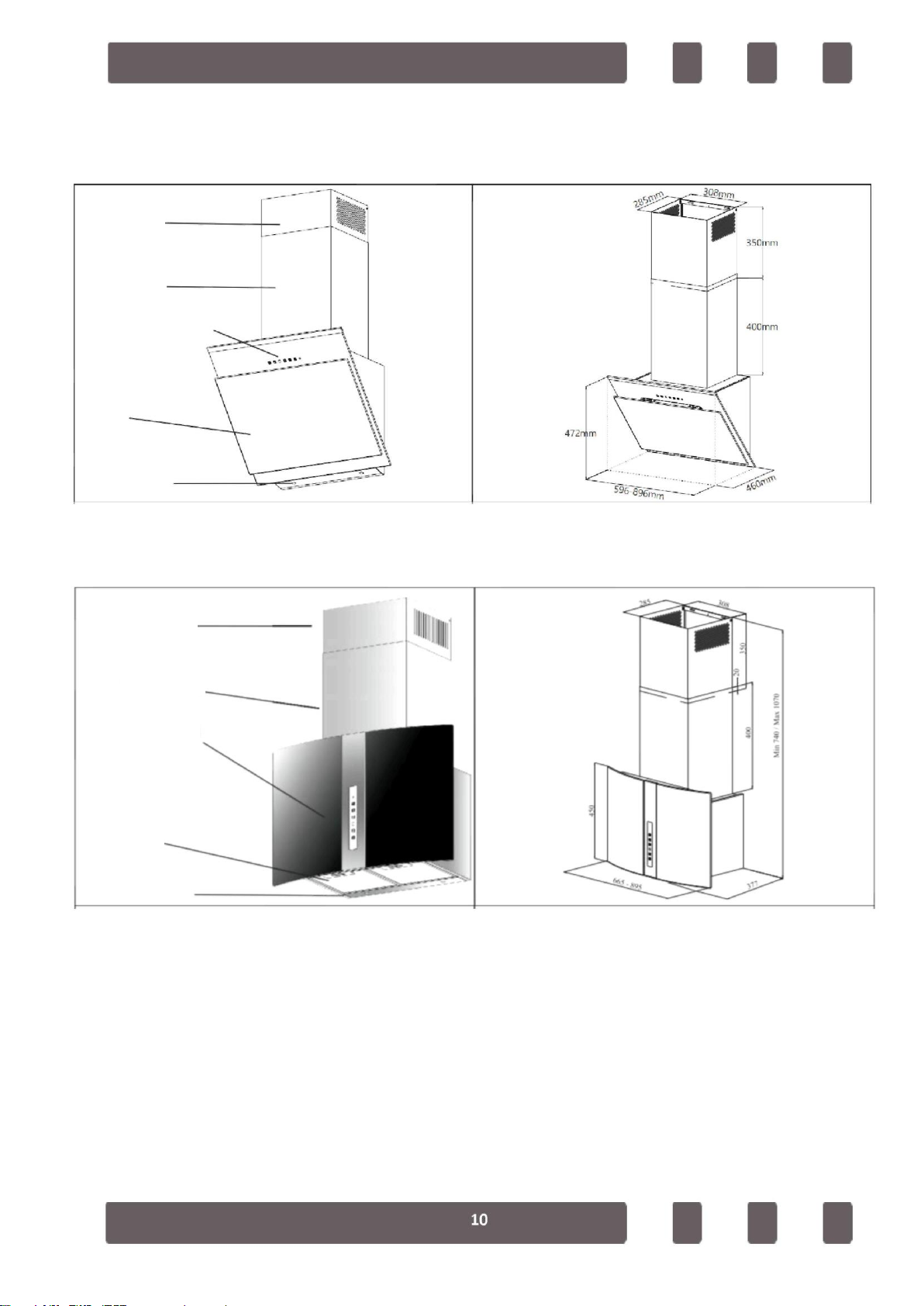
2.2. Drawings of the Appliance
2.2.1 T8630SM / T8631SM / T8632SM / T8731SM /T8930SM / T8931SM / T8932SM
Inner Flue
Min. 545mm/Max. 870mm
Outer Flue
Control Panel
Filter
Lighting
2.2.2. T8633SM / T8634SM / T8933SM / T8934SM / T8635SM /T8935SM / T8636SM /
T8936SM / T8638SM / T8938SM /T8670SM / T8671SM / T8652SM / T8952SM
Inner Flue
Outer Flue
Control panel
Lighting
Filter
2.2.3. T8639SM / T8939SM / T8640SM / T8940SM / T8649SM / T8949SM / T8650SM /
T8950SM / T8658SM / T8668SM / T8645SM / T8945SM / T8646SM / T8946SM /T7639SM /
T8651SM / T8653SM / T8655SM / T8656SM / T8673SM
Inner Flue
Outer Flue
Control panel
Filter
Lighting
2.2.4. T8643SM / T8644SM / T8743SM / T8743SM / T8744SM / T8641SM / T8642SM
Inner Flue
Outer Flue
Control panel
Filter
Lighting

2.2.5. T8954SM / T8956SM (Island Type)
Inox Crown
Inner Flue
Outer Flue
Control panel
Lighting
Filter
3. INSTALLATION OF THE HOOD
3.1. INSTALLATION OF HOOD MODELS T8630SM / T8631SM / T8632SM / T8731SM
/T8930SM / T8931SM / T8932SM
Electric Cooker
Min: 550 mm. / Max.: 750 mm. Gas Cooker
Min.: 750 mm. / Max.: 800 mm.
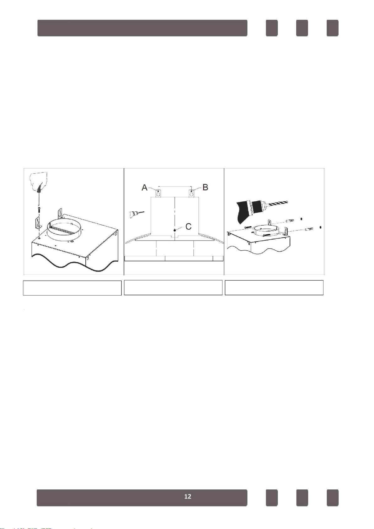
Installation of the Hanger Plate to the Hood
Secure 2 (two) hanger plates provided with the installation accessories to the
hood with 1 tightening nut screw as shown in Figure 1. Ensure that the
hanger plates are secured in their seats.
Installation of the Hanger Plate to the Wall
Drive 8 mm dowels to the holes (A, B, C) drilled as per the installation
template. Secure the hanger plate to the wall using 2 chipboard screws as
shown in Figure 2.
Installation Template
Figure 2
Figure 1
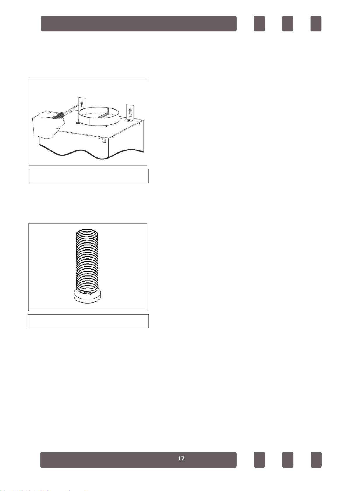
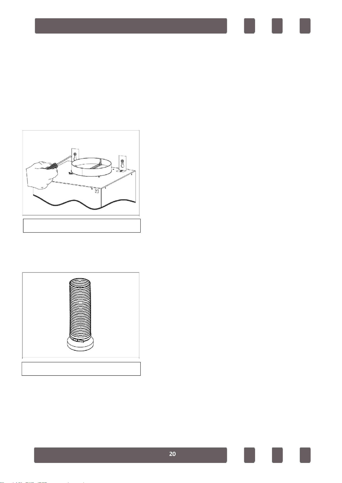
Installation of the Inner Flue Hanger Plate
Drill 2 securing holes on the wall at a suitable height and at required locations
using a Ø6mm drill to secure the inner flue hanger plate. Drive 6 mm dowels to
these holes and secure the inner flue hanger plate. At the end of the installation
of the hood, screw the inner flue to the hanger plate from the corresponding
points.
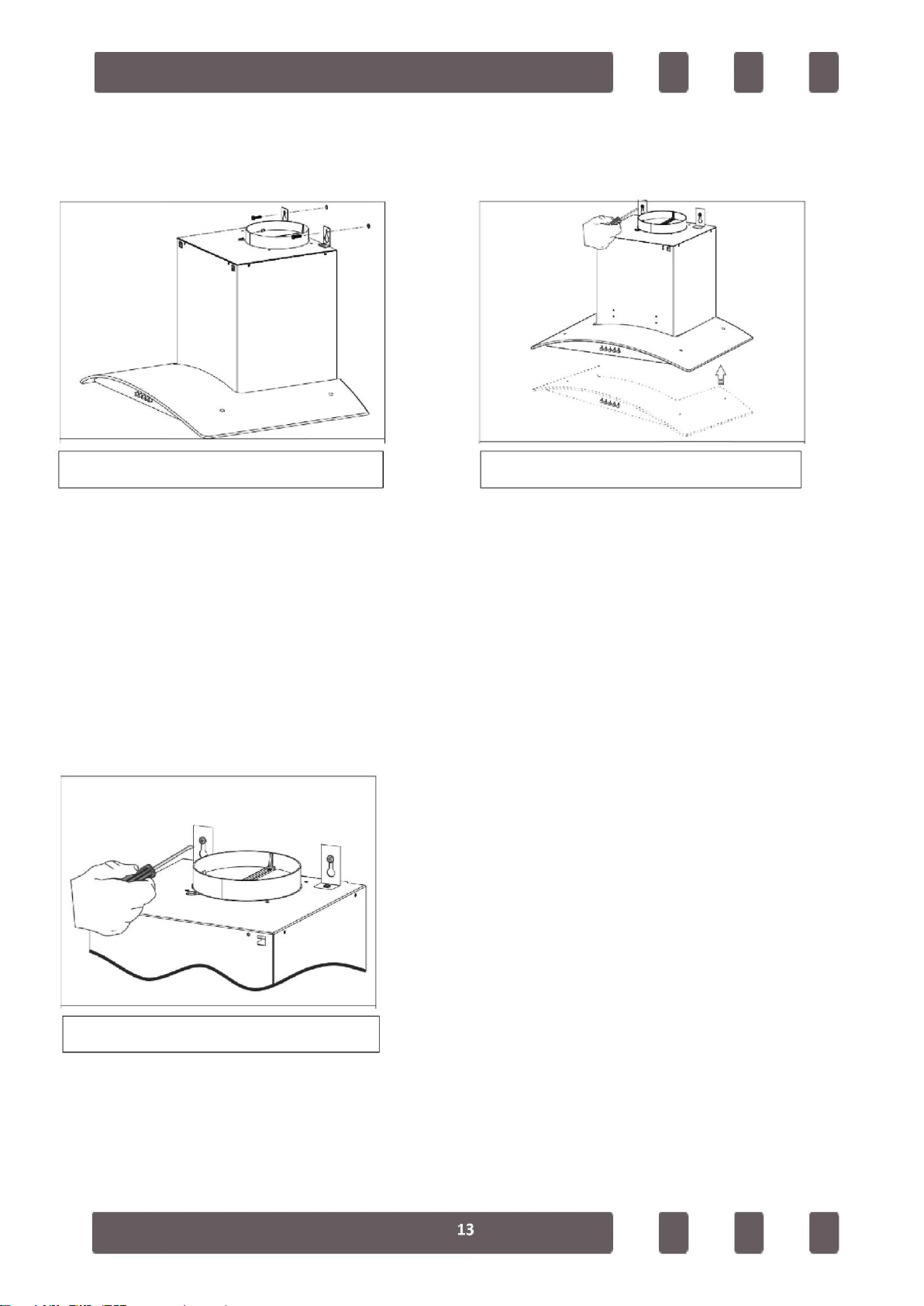
Hanging the Hood to the Wall
Raise the hood holding its body and connect hanging plates to the dowels on
the wall as shown in Figure 3.
Figure 3 Figure 4
Bringing the Hood to a Parallel Position to the Ground
In case of skewness on the appearance of the hood, use adjustment screws
shown in Figure 4 to bring the hood parallel to the ground.
Tighten the bolts shown in Figure 5 securely when the levelling operation is
complete. After securing the hood completely, secure the body from the holes
(C, D) on the body using two screws to prevent it from moving.
Figure 5
Installation of the Aluminium Pipe
Mount the flexible aluminium pipe on the plastic flue. Install the other end of the
pipe to the flue hole on the kitchen (See Figure 6)
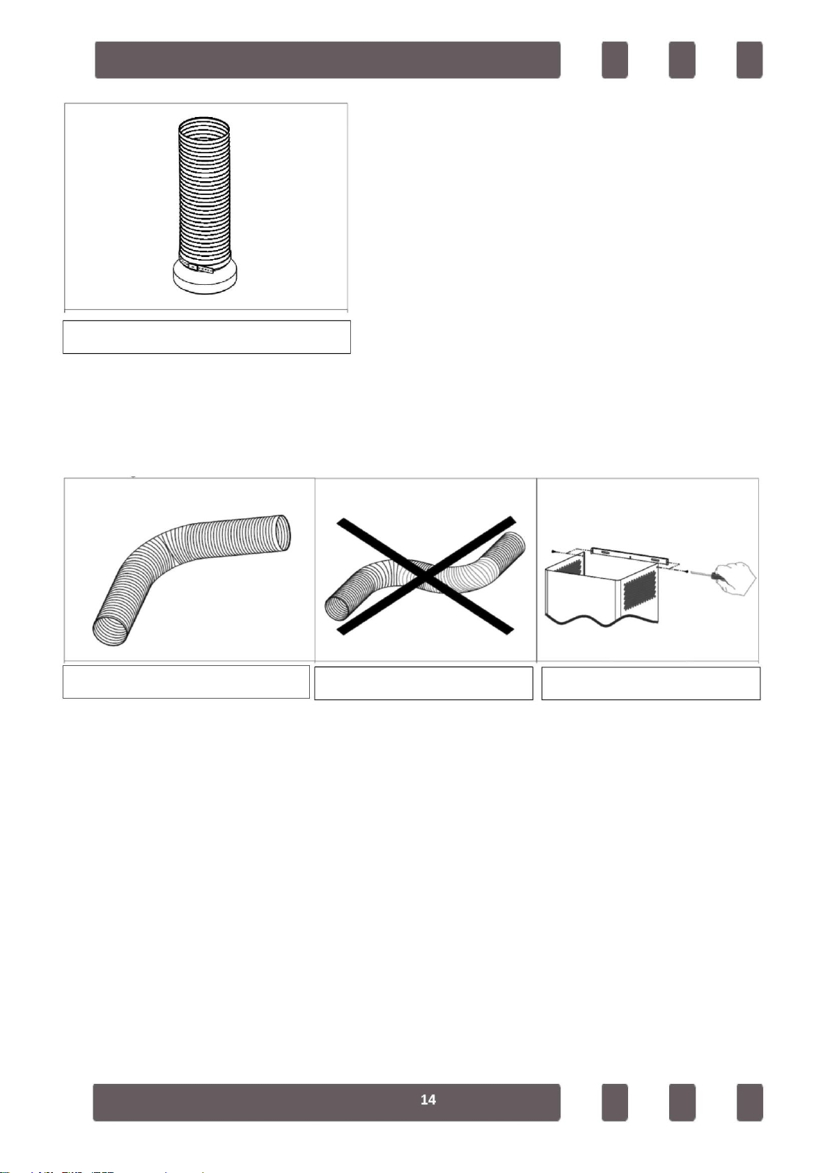
Figure 6
Since twists and bends in the aluminium pipe will lead to reduction in the air
suction power, avoid using twists and bends as much as possible. Place the
inner flue and outer flue on the appliance carefully. Secure the inner flue to the
inner flue connection plate with 2 screws. (See Figure 9)
Figure 7
Figure 8 Figure 9

3.2. INSTALLATION OF HOOD MODELS T8633SM / T8634SM / T8933SM /
T8934SM / T8635SM /T8935SM / T8636SM / T8936SM / T8638SM /
T8938SM /T8670SM / T8671SM / T8652SM / T8952SM
Installation of the Hanger Plate to the Hood
Secure 2 (two) hanger plates provided with the installation accessories
to the hood with 1 tightening nut screw as shown in Figure 1. Ensure
that the hanger plates are secured in their seats.
Installation of the Hanger Plate to the Wall
Drive 8 mm dowels to the holes (A, B, C) drilled as per the installation
template. Secure the hanger plate to the wall using 2 chipboard screws
as shown in Figure 2.
Electric Cooker
Min: 650 mm. / Max.: 750 mm. Gas Cooker
Min: 750 mm. / Max.: 800 mm.

Installation Template
Picture
Figure 1
Installation of the Inner Flue Hanger Plate
Drill 2 securing holes on the wall at a suitable height and at required locations
using a Ø6mm drill to secure the inner flue hanger plate. Drive 6 mm dowels to
these holes and secure the inner flue hanger plate. At the end of the installation
of the hood, screw the inner flue to the hanger plate from the corresponding
points.
Hanging the Hood to the Wall
Raise the hood holding its body and connect hanging plates to the dowels on
the wall as shown in Figure 3.
Figure 3 Figure 4
Bringing the Hood to a Parallel Position to the Ground
In case of skewness on the appearance of the hood, use adjustment screws
shown in Figure 4 to bring the hood parallel to the ground.
Tighten the bolts shown in Figure 5 securely when the levelling operation is
complete. After securing the hood completely, secure the body from the holes
(C, D) on the body using two screws to prevent it from moving.
Figure 5
Installation of the Aluminium Pipe
Mount the flexible aluminium pipe on the plastic flue. Install the other end of the
pipe to the flue hole on the kitchen (See Figure 6)
Figure 6
Since twists and bends in the aluminium pipe will lead to reduction in the air
suction power, avoid using twists and bends as much as possible. Place the
inner flue and outer flue on the appliance carefully. Secure the inner flue to the
inner flue connection plate with 2 screws. (See Figure 9)

Figure 8
Figure 9
Figure 7
3.3. INSTALLATION OF HOOD MODELS T8639SM / T8939SM / T8640SM /
T8940SM / T8649SM / T8949SM / T8650SM / T8950SM / T8658SM / T8668SM /
T8645SM / T8945SM / T8646SM / T8946SM /T7639SM / T8651SM / T8653SM /
T8655SM / T8656SM / T8673SM
Gas Cooker
Min.: 550 mm. / Max.: 650 mm.
Electric Cooker
Min: 450 mm. / Max.: 550 mm.

Installation of the Hanger Plate to the Hood
Secure 2 (two) hanger plates provided with the installation accessories
to the hood with 1 tightening nut screw as shown in Figure 1. Ensure
that the hanger plates are secured in their seats.
Installation of the Hanger Plate to the Wall
Drive 8 mm dowels to the holes (A, B, C) drilled as per the installation
template. Secure the hanger plate to the wall using 2 chipboard screws
as shown in Figure 2.
Figure 2
Figure 1 Installation Template
Installation of the Inner Flue Hanger Plate
Drill 2 securing holes on the wall at a suitable height and at required locations
using a Ø6mm drill to secure the inner flue hanger plate. Drive 6 mm dowels to
these holes and secure the inner flue hanger plate. At the end of the installation
of the hood, screw the inner flue to the hanger plate from the corresponding
points.
Hanging the Hood to the Wall
Raise the hood holding its body and connect hanging plates to the dowels on
the wall as shown in Figure 3.
Figure 3 Figure 4
Bringing the Hood to a Parallel Position to the Ground
In case of skewness on the appearance of the hood, use adjustment screws
shown in Figure 4 to bring the hood parallel to the ground.
Tighten the bolts shown in Figure 5 securely when the levelling operation is
complete. After securing the hood completely, secure the body from the holes
(C, D) on the body using two screws to prevent it from moving.
Figure 5
Installation of the Aluminium Pipe
Mount the flexible aluminium pipe on the plastic flue. Install the other end of the
pipe to the flue hole on the kitchen (See Figure 6)
Figure 6
Since twists and bends in the aluminium pipe will lead to reduction in the air
suction power, avoid using twists and bends as much as possible. Place the
inner flue and outer flue on the appliance carefully. Secure the inner flue to the
inner flue connection plate with 2 screws. (See Figure 9)
This manual suits for next models
109
Table of contents
Other Simfer Ventilation Hood manuals


