Simfer 8668 User manual
Instruction Manual
DECORATIVE CHIMNEY HOOD
DEKORATIVNA KAMINSKA NAPA
GB
H10-20-300-031 Rev 001
Navodila za uporabo SI

Dear Customer,
Thank you very much for your preference for Simfer products. Our
objective is to ensure that you enjoy this product, manufactured
environmentally-friendly with a total sense of quality in a precise working
environment at our modern facilities, most efficiently.
We recommend you to read the instruction manual carefully and keep
it handy before you use this Simfer chimney hood so that it maintains its
quality just like the first day you bought it and serves you most efficiently.
NOTE:
This Instruction Manual has been prepared for a variety of models.
Some of the features specified in the Manual may not exist in your device.
These features are marked with *.
Our devices are designed for domestic use. They are not for
professional use.
"PLEASE READ THE INSTRUCTIONS BEFORE YOU INSTALL OR
USE THIS DEVICE."
This product has been manufactured in an environmentally-friendly
and modern plants without harming the nature.
“Conforms with the EEE Regulations."
GB

CONTENTS:
1.SAFETY INTRODUCTIONS 3
2. INTRODUCTION AND TECHNICAL DRAWING OF THE CHIMNEY HOOD... 4
3.INSTALLATION OF CHIMNEY HOOD........................................ 5
3.1.Location of the Chimney Hood.........................
3.2.Installation of Mounting Bracket to the Chimney
Hood...................................................................
3.3.Installation of Wall Mounting Bracket...............
3.4.Installation of Inner Duct Mounting Bracket .....
4.MOUNTING THE CHIMNEY HOOD ON THE WALL..........................6
4.1.Leveling the Chimney Hood..............................
4.2.Mounting the Aluminum Pipe...........................
5. .....................................7FUNCTIONS OF THE CHIMNEY HOOD
5.1.Control Panel and its Functions.......................
5.2.Operating the Chimney Hood..........................
5.3.In ducted use................................................
5.4.Round Charcoal Filter.....................................
5.5.Use of Charcoal Filter.....................................
5.6.Installation of Charcoal Filter..........................
5.7.Use of Aluminum Cartridge Filter.....................
6.REPLACING THE BULB........................................................ 9
7.MAINTENANCE OF THE CHIMNEY HOOD................................. 10
8.IF CHIMNEY HOOD DOES NOT WORK.....................................11

1.SAFETY INSTRUCTIONS
ŸThis product is designed for domestic use.
ŸProduct Voltage is 220-240 Volts 50Hz.
ŸPower cord of your product is fitted with grounded plug. This cord must be
plugged into a grounding socket.
ŸAll electrical installation must be done by a qualified electrician.
ŸInstallation by unqualified persons may lead the product run with lower
performance, be damaged or cause accidents.
ŸPower supply cord should not be jammed or crushed. Power cord should
not be close to hobs, etc, otherwise it may melt and cause fire.
ŸDo not plug in the product into a socket before the installation is complete.
ŸMake sure the mains switch is easily accessible in order to cut the power of
the product in case of any danger.
ŸDo not touch the bulbs of your product if used for a long period of time. The
bulbs will be hot and may burn your hand.
ŸKitchen chimneys are designed for domestic use. If used for other
purposes, it may lead to a failure and not be covered under the warranty.
ŸFollow the authorized agencies' rules and regulations regarding letting out
the air. (This warning does not apply to usage with non-ducted chimney
hoods.)
ŸFood that may burst into flames should not be cooked under the device.
ŸTurn on the product after you place pots, pans, etc on the hobs. Otherwise
excess heat may cause deformation of some parts of your product.
ŸDo not leave hot oil on the hobs. Pans with hot oil inside may cause self-
ignition.
ŸWhen cooking i.e. deep frying, hot oil may burst into flames. Be careful on
your curtains and cloths.
ŸMake sure you replace the filters at the recommended intervals. Filters not
replaced on time carry fire risk due to increase of grease on them.
ŸDo not use non-fire-resistant materials instead of filters.
ŸKeep the potentially dangerous packaging materials away from children.
ŸDo not use your product without a filter, do not remove filters when the
product is operating.
ŸIn case of start of flames, cut off the power of the chimney fan and cooker.
(Cut off the power by unplugging the device).
GB
3
1.SAFETY INSTRUCTIONS
ŸTurn off the hobs before you remove pots, pans, etc.
ŸIf the cleaning is not done periodically, your product may carry fire risk.
ŸCut off the power supply before any maintenance work. (Cut off the power
by unplugging the device.)
ŸFor duct-out chimney hoods, use pipes with a diameter of 150mm or
120mm. You should minimize the ducting distance with minimum bends.
ŸMake sure your children do not play with the product. Do not let young
children operate the product.
ŸIf the power cord is damaged, the damaged cord should be replaced by the
manufacturer or its service agent or similarly specialized personnel in
order to avoid a dangerous situation.
ŸIn case of start of flames, cut off the power of the chimney fan and cooker
and cover the flame. Do not use water to extinguish the fire.
Install "MAX 6 A" fuse for the extractor fan.
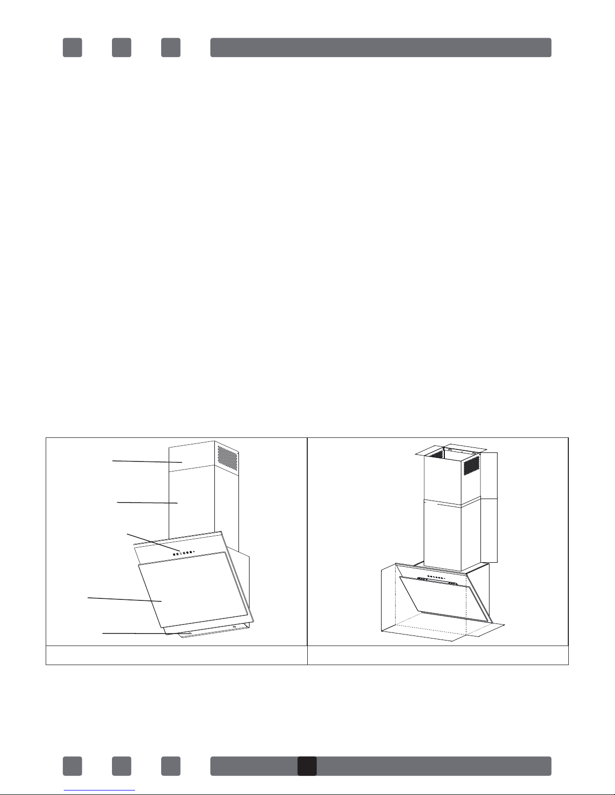
2. INTRODUCTION AND TECHNICAL DRAWING OF THE CHIMNEY HOOD
4
Inner Duct
Outer Duct
Lighting
Filter
Control Panel
472mm
400mm
350mm
285mm
308mm
460mm
596-896mm
GB
5
0
80
50
130
220
180
250
MAX
90
80
70
40
30
10
20
50
0
60
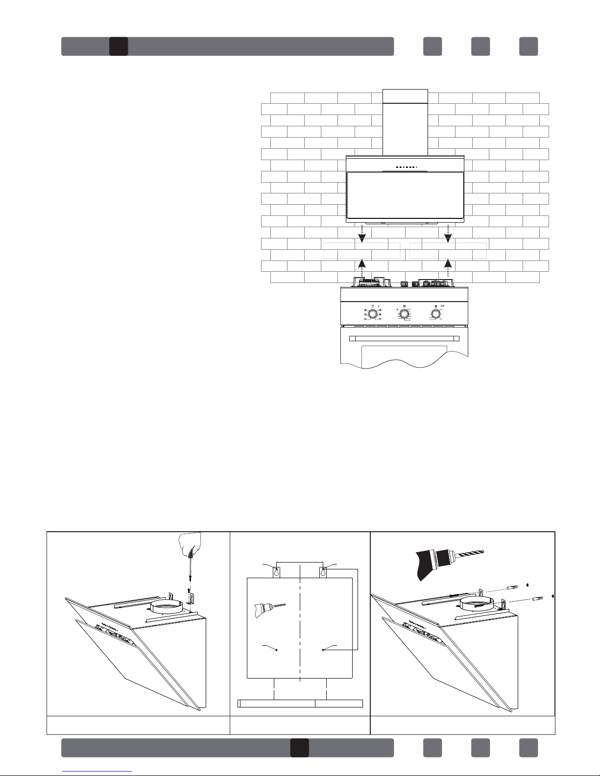
Electric Stove
Min.: 450 mm. / Max.:550 mm.
Gas Stove
Min.: 550 mm. / Max.:650 mm.
3.INSTALLATION OF CHIMNEY HOOD
3.1.Location of the Chimney Hood
3.2.Installation of Mounting Bracket to the Chimney Hood
Fix the 2 (two) Mounting brackets among the installation accessories to the
chimney hood with one 1 screw nut as shown in Figure 1. Make sure mounting
brackets are inserted in motor box.
3.3.Installation of Wall Mounting Bracket
3 drywall (8mm) anchors are nailed into the holes drilled according to
installation template (A,B,C,D). They are fixed into the wall with 2 brackets as
shown in Figure 2.
A
C D
B
Installation Template
Fig 1 Fig 2

6
Fig 3 Fig 4
3.4.Installation of Inner Duct Mounting Bracket
2 fixing holes are drilled on the wall with Ø6mm electric drill at a suitable
height and place to fix the inner duct hanger plate onto the wall. 6mm drywall
anchors are nailed into those holes and inner duct mounting brackrets are
pinned down.
At the last step of chimney hood installation, the inner duct is screwed on the
inner duct mounting brackets.
4.MOUNTING THE CHIMNEY HOOD ON THE WALL
Lift the chimney hood body and fix the hanger plates onto the wall anchors as
shown in Figure 3.
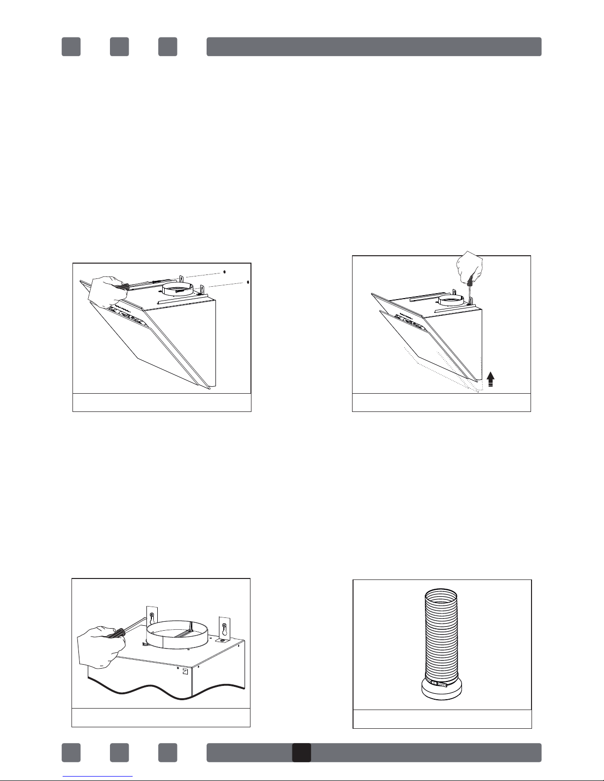
4.1.Leveling the Chimney Hood
If the chimney hood is inclined on one side, the chimney hood can be leveled
with the adjustment screws as shown in Figure 4.
Once the balancing is complete, the screws shown in Figure 5 must be fixed
tightly.
After this, fix the body with one screw through the hole on the body.
4.2.Mounting the Aluminum Pipe
Place the aluminum pipe on the plastic duct. Place the other end of the pipe
into the air outlet in the kitchen. Figure 6
Fig 5 Fig 6
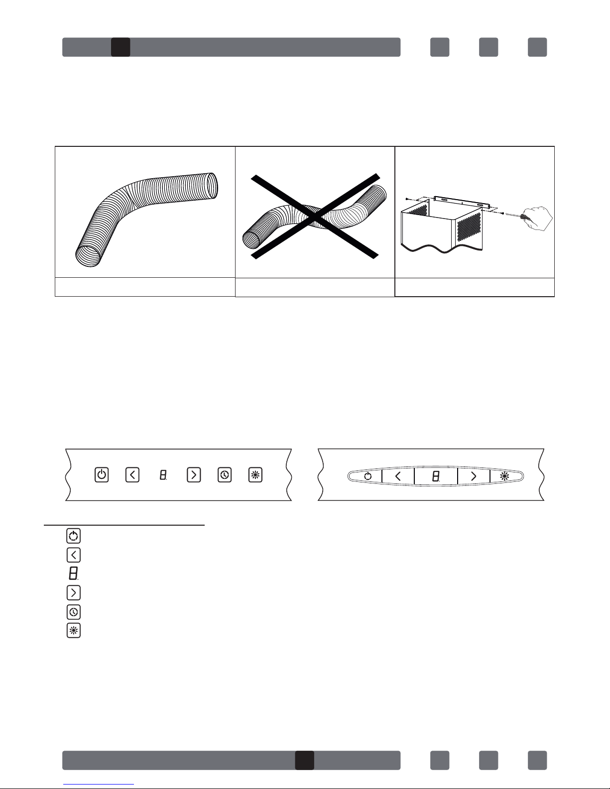
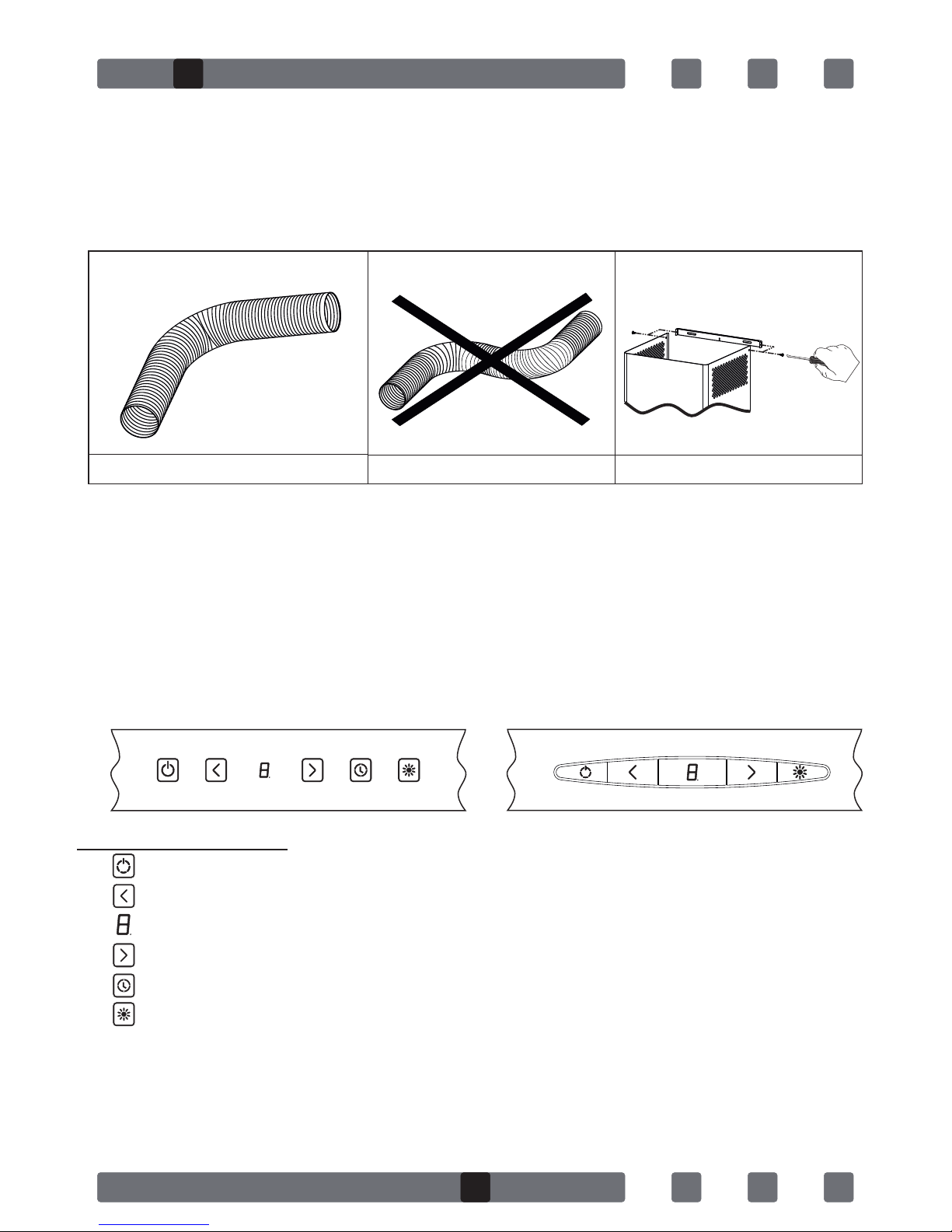
Twists and bends on the aluminum pipe may cause minimizing the air suction
so avoid unnecessary bends and twists as much as possible.
Place the inner duct and outer duct carefully on the product. Fix the inner
duct to inner duct connection plate with 2 screws. (Figure 9)
5.FUNCTIONS OF THE CHIMNEY HOOD
5.1.Control Panel
ŸTouch Control: Touch the symbols on the glass surface. If Press a symbol
longer (more 3 sec) may operate various functions.
ŸDigital Control: touch the symbols on the keys. (On/Off function and timer
are on the same key; if pressed for 1 sec on-off function will operate. If
pressed for 3 sec. 15 minutes timer will operate.
Note: When the product operates for a certain time, the aluminum filters
get dirty and the digital display shows "C" Clean sign. This means the
filters should be cleaned. Press the speed reduction key for 5 secs in
order to delete "C" sign from the display.
Fig 7 Fig 8 Fig 9
SYMBOLS FUNCTIONS
ŸSwitches on and off the motor. (Except for the lighting)
ŸDecreases the speed when the motor is running.
ŸDisplay
ŸIncreases the speed when the motor is running.
ŸIf pressed this symbol, the motor turns itself off 15 minutes later.
ŸOnly switches on and off the lighting system.
GB
7

8
New Function!
When the timer key is pressed for 3 secs digital display starts to change.
Air-circulation system of the chimney hood becomes active. The chimney
hood runs for 10 minutes in the lowest speed. Then the system automatically
shuts down.
5.2.Operating the Chimney Hood
Chimney hood is used in ducted and non-ducted kitchens.
5.3.In ducted use;
In ducted use, extractor fan should be connected to an air outlet to send the
air out. In order to use your chimney hood efficiently, make sure length of the
pipe system between the chimney hood and the air outlet should be short.
Your product has been manufactured suitable for ducted and non-ducted
use.
5.4.Round Charcoal Filter
In kitchens with no duct, a round charcoal filter should be reintroduced the
clean air into the kitchen. You can obtain the round filter from your service or
dealer.
5.5.Use of Charcoal Filter
ŸOur products allow the installation of charcoal filter
ŸRegardless of use of charcoal filters or not, grease filters should be
installed on the product. Do not use your product without grease filter.
ŸUse of charcoal filteris as follows.
ŸCut off the device power before replacing charcoal filter.
ŸCharcoal filter is used in the kitchens with no duct therefore should be
replaced in every 3-5 months depending on the frequency of use.
ŸCharcoal filter should never be washed.
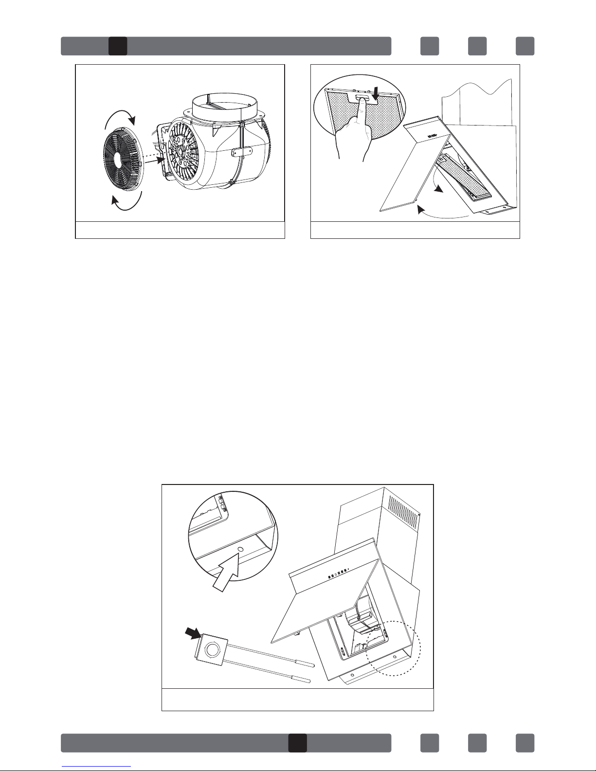
5.6Installation of Charcoal Filter
ŸCharcoal filters are used in the kitchens with no duct.
ŸCharcoal filters are installed onto both sides of the fan as shown in Figure
10 by turning 10 degrees clock-wise.
ŸWhen uninstalling, reverse the same procedure.
5.7Use of Aluminum Cartridge Filter
ŸAluminum cartridge filter holds dust and grease in the air. Chimney hood
should never be used without aluminum cartridge filter. Figure 11
GB
9
Fig 12
Kırmızı
Siyah
1
2
6.REPLACING THE BULB
Always switch off the electrical supply before carrying out any operation
ŸLED bulb does not operate is possible to remove as shown in Figure 12
ŸA new bulb to be supplied from service points is replaced with the same
reoperation.
ŸCables are designed with sockets. The plug in should be made according
to previous connection.
Note: Remove the holder on the LED bulb as shown in Figure 12/2 . Put the
new LED bulb on the holder housing of the LED bulb you removed as shown in
Figure 12/1 .
Installing Posion
Fig 10 Fig 11

10
7.MAINTENANCE OF THE CHIMNEY HOOD
ŸDevice should be unplugged or switch should be turned off before cleaning
and maintenance procedures.
ŸMetal filter should be cleaned once a month with hot soapy water or in the
dishwasher, if possible. (60 °C)
ŸRemove the aluminum cartridge filter by pressing on the spring catches on
the side. Do not refit before drying after wash.
ŸOuter surface of the extractor hood should be wiped with a damp cloth
soaked with soapy water.
ŸMake sure electronic parts do not contact with water or similar materials.
ŸFor inox products, using inox cleaning and maintenance products
available in the market will provide longer usage life for your device.
ŸAluminum filters can be washed in dishwasher. After several washes,
aluminum filters may change colour. This is normal and filters do not need
to be replaced.
WARNING
When used with devices which use fuel (heaters working with gas, diesel fuel,
coal or firewood, water heaters, etc) and the air in the environment; should be
used cautiously. The chimney hood sending the air out in the environment
may affect the burning adversely.
This warning is not applicable to non-ducted use.
Efficient use of Chimney Hood
ŸWhen installing the chimney hood to the air duct, use 150/120 mm
diameter pipes and use bends as minimum as possible.
ŸBe ware of cleaning periods of metal filters and replacing times of charcoal
filters.
ŸWhen dense suction power is not required, use the product in medium
setting.
ŸFor right ventilation, the windows in the kitchen leading to the outside
should be kept closed.

X X
X XX
X XX
XX
Chimney Hood does not
work
Light bulb is not
working
Chimney hood air
suction is poor
Do not send air out (in
non-ducted cases)
Check electricity connection (mains
voltage should be 220-240 V, Chimney
hood should be connected to grounding
socket.)
Check motor switch (Motor switch should
be on.)
Check bulb switch (Bulb switch should be
on.)
Check aluminum filter (Aluminum
cartridge filter should be washed once a
month in normal use.)
Check bulbs (Bulbs should be in working
condition.)
Check air outlet shaft (Air outlet shaft
should be unblocked.)
Check charcoal filter (Charcoal filters
should be replaced quarterly in normal
use.)
8.IF CHIMNEY HOOD DOES NOT WORK
Before contacting the service, make sure the product is plugged and the fuse
in the electrical installation is working. Do not do anything that may harm the
product.
Service and spare parts:
Have one of our authorized services install your device free of charge.
You can supply spare parts of your device from your dealer or authorized
services.
The package includes a list of authorized services with the product.
When you contact your service or dealer to ask for any spare parts, notify them
of product model name shown in the product label. When you remove the
aluminum cartridge filter, you will see the product label.
Before contacting your service, check your chimney hood against the table
below. If problem persists, contact your dealer or authorized service point.
TR
GB
11

Spoštovani uporabnik!
Veseli nas, da ste izbrali izdelke Simfer. Želimo si, da bi izdelek, ki smo ga
izdelali na okolju prijazen nain in upoštevanju kakovosti v natanno
nadzorovanem delovnem okolju v našem sodobnem obratu, uporabljali im
bolj uinkovito in z veseljem.
Svetujemo vam, da pred uporabo nape Simfer natanno preberete navodila
za uporabo in jih shranite na prironem mestu ter ohranjate njegovo
izvorno kakovost in ga im uinkoviteje uporabljate.
OPOMBA:
navodila za uporabo so pripravljena za razline modele. Nekatere lastnosti,
navedene v navodilih, morda ne veljajo za vašo napravo. Te lastnosti so
oznaene s simbolom *.
Naše naprave so zasnovane za domao uporabo in niso namenjene
profesionalni uporabi.
»PRED NAMESTITVIJO ALI UPORABO NAPRAVE PREBERITE TA
NAVODILA ZA UPORABO.«
Izdelek je bil izdelan v okolju prijaznem in sodobnem obratu brez vpliva na
okolje.
»Skladnost z uredbami o elektrini in elektronski opremi (EEE).«
SI
12

VSEBINA:
1. VARNOSTNA OPOZORILA..................................................1 4
2. PREDSTAVITEV IN TEHNIČNA SKICA NAPE............................ 15
3. NAMESTITEV NAPE ........................................................... 16
3.1. Mesto Namestitve Nape....................................
3.2. Pritrditev namestitvenega okvirja na napo...........
3.3. Namestitev stenskega namestitvenega okvirja......
3.4. Namestitev okvirja notranje cevi.........................
4.NAMESTITEV NAPE NA STENO..............................................17
4.1. Izravnava nape..................................................
4.2. Nameščanje aluminijaste cevi.............................
5.LASTNOSTI NAPE...............................................................18
5.1. Funkcije nadzorne plošče..................................
5.2. Uporaba nape..................................................
5.3. Uporaba z zračnikom........................................
5.4. Okrogli ogleni filter...........................................
5.5. Uporaba oglenega filtra.....................................
5.6. Namestitev oglenega filtra.................................
5.7. Uporaba aluminijastega kasetnega filtra.............
6. MENJAVANJE SIJALKE........................................................ 20
7. VZDRŽEVANJE NAPE.......................................................... 22
8. ODPRAVLJANJE NAPAK V DELOVANJU NAPE............................23
13

1. VARNOSTNA NAVODILA
ŸTa naprava je zasnovana za domačo uporabo.
ŸIzdelek je primeren za delovanje pri napetosti 220–240 V pri frekvenci 50
Hz.
ŸNapajalnik naprave je opremljen z ozemljenim vtičem. Napajalnik
vključite v ozemljeno vtičnico.
ŸElektrično namestitev mora izvesti usposobljen električar.
ŸČe namestitev izvede neusposobljena oseba, lahko pride do zmanjšane
učinkovitosti delovanja naprave, poškodbe naprave ali nesreče pri njeni
uporabi.
ŸNapajalni kabli ne smejo biti zagozdeni ali stisnjeni. Napajalnega kabla ne
približujte grelnim ploščam/gorilnikom itd., saj se lahko stopijo in
povzročijo požar.
ŸNaprave ne vključite v vtičnico, preden do konca ne izvedete namestitve.
ŸZagotovite, da je omrežno stikalo lahko dostopno, da lahko v primeru
nevarnosti hitro prekinete napajanje naprave.
ŸNe prijemajte sijalk naprave ob njeni dolgotrajnejši uporabi, saj so vroče,
zaradi česa lahko dobite opekline.
ŸKuhinjske nape so zasnovane za domačo uporabo. Ob nenamenski uporabi
nap lahko pride do okvare in posledične razveljavitve garancije.
ŸGlede odvajanja zraka upoštevajte pravila in predpise pooblaščenih
agencij. (To opozorilo ne velja za uporabo nape brez zračnika.)
ŸPod napo ne pripravljajte hrane, ki lahko zagori.
ŸNapravo vklopite šele, ko na grelno ploščo/gorilnike namestite posode,
ponve itd. V nasprotnem primeru lahko prekomerna toplota povzroči
deformacijo nekaterih delov naprave.
ŸNa grelni plošči/gorilnikih ne puščajte vročega olja. Vroče olje v ponvi
lahko spontano zagori.
ŸMed kuhanjem, zlasti cvrtjem, lahko vroče olje zagori. Zaščitite zavese in
oblačila.
ŸFiltre menjajte v priporočenih intervalih. Filtre, ki jih ne menjate
pravočasno, vključujejo tveganje požara zaradi kopičenja maščobe.
ŸFiltrov ne nadomeščajte z materiali, ki niso odporni proti požaru.
ŸPotencialno škodljivo embalažo shranite zunaj dosega otrok.
14
SI

Notranji del
Zunanji del
zračnika
Osvetlitev
Filter
Nadzorna
plošča
472mm
400mm
350mm
285mm
308mm
460mm
596-896mm
1. VARNOSTNA NAVODILA
ŸNaprave ne uporabljajte brez nameščenega filtra in filtrov ne odstranjujte
med delovanjem naprave.
ŸV primeru zanetenja ognja prekinite napajanje nape in kuhalnika.
(Izključite napravo s prekinitvijo napajanja.)
ŸGrelno ploščo/gorilnike pred odstranjevanjem posod, ponev itd. izklopite.
ŸČe čiščenja ne izvajate redno, lahko naprava vključuje nevarnost požarov.
ŸPred vzdrževanjem izključite napajanje. (Izključite napravo s prekinitvijo
napajanja.)
ŸZa nape z zračnikom uporabite cevi s premerom od 120 do 150 mm.
Dolžino zračnika zmanjšajte tako, da vsebuje čim manj zavojev.
ŸOtrokom preprečite igranje z napravo. Majhnim otrokom preprečite
uporabo naprave.
ŸČe je napajalni kabel poškodovan, ga mora za preprečitev nevarnosti
zamenjati proizvajalec ali njegov servisni zastopnik ali podobno
usposobljena oseba.
ŸV primeru zanetenja ognja prekinite napajanje nape in kuhalnika ter
plamene pokrijte s posodo. Požara ne gasite z vodo.
Ÿ
Za odvodni ventilator namestite varovalko z največjo močjo 6 A.
2. PREDSTAVITEV IN TEHNIČNA SKICA NAPE
15

0
80
50
130
220
180
250
MAX
90
80
70
40
30
10
20
50
0
60
Električni kuhalnik
Najm.: 450 mm/najv.: 550 mm
Plinski kuhalnik
Min.: 550 mm. / Max.:650 mm.
3. NAMESTITEV NAPE
3.1. MESTO NAMESTITVE NAPE
3.2. Pritrditev Namestitvenega Okvirja na Napo
Dva (2) namestitvena okvirja, ki sta na voljo med dodatki za namestitev,
pritrdite na napo z enim vijakom z matico tako, kot je prikazano na sliki 1.
Zagotovite, da namestitvena okvirja vstavite v ohišje motorja.
3.3 Namestitev Stenskega Namestitvenega Okvirja
Tri (3) sidrne vijake za mavčne plošče (premera 8 mm) privijte v izvrtine glede
na namestitveno shemo (A,B,C,D). Na steno so pritrjeni z dvema (2)
namestitvenima okvirjema, kot je prikazano na sliki 2.
16
A
C D
B
Namestitvena shema
Slika 1 Slika 2
SI
Slika 3 Slika 4
3.4. Namestitev Okvirja Notranje Cevi
V steno z električnim vrtalnikom s svedrom premera 6 mm izvrtajte dve (2)
pritrdilni odprtini na ustrezni višini in okvir pritrdite, da boste lahko nanj
namestili ploščo za notranji zračnik. V te izvrtine pričvrstite sidrne vijake za
mavčne plošče premera 6 mm, da pritrdite namestitvene okvirje.
V zadnjem koraku namestitve nape notranji zračnik privijte na namestitveni
okvir.
4. NAMESTITEV NAPE NA STENO
Dvignite ogrodje nape in obesno ploščo namestite na sidrne stenske vijake,
kot je prikazano na sliki 3.
4.1. Izravnavanje Nape
Če je napa ob strani nagnjena, jo lahko izravnate s nastavitvenimi vijaki, kot
je prikazano na sliki 4.
Po izravnavi nape tesno privijte vijake, prikazane na sliki 5.
Napo nato pritrdite z enim vijakom, ki ga vstavite skozi odprtino v ohišju.
4.2. Nameščanje Aluminijaste Cevi
Aluminijasto cev namestite na plastični zračnik. Drugi konec cevi vstavite v
odprtino za odvod zraka v kuhinji. Slika 6
17
Slika 5 Slika 6
Zavoji in ukrivljenost aluminijaste cevi lahko vpliva na slabše sesanje zraka,
zato se jim pri namestitvi v čim večji meri izogibajte. (Slika 7-8)
Notranji in zunanji del zračnika previdno namestite na napravo. Notranji
del zračnika z dvema (2) vijakoma namestite na notranjo ploščo za
namestitev zračnika. (Slika 9)
5. FUNKCIJE KAMINSKE NAPE
5.1. Nadzorna plošca
ŸNadzor na dotik: dotaknite se simbolov na stekleni površini. S pridržanjem
simbola (dlje kot 3 sekunde) lahko vklopite ve funkcij.
ŸDigitalni nadzor: dotaknite se simbolov na tipkah. Funkciji za vklop/izklop
in asovnik so na isti tipki; e tipko pritisnete in jo držite 1 sekundo, se bo
vklopila funkcija za vklop/izklop. e jo pritisnete in držite 3 sekunde, se bo
vklopil 15-minutni asovnik.
Opomba: Po določenem času delovanja nape se aluminijasti filtri zamašijo
in na zaslonu se prikaže znak »C« za čiščenje. To pomeni, da je treba filtre
očistiti. Pritisnite tipko za zmanjšanje hitrosti in jo držite 5 sekund, če
želite izbrisati znak »C« na zaslonu.
Slika 7 Slika 8 Slika 9
SIMBOLI FUNKCIJE
ŸVklop in izklop motorja. (ne vpliva na osvetlitev)
ŸZnižanje hitrosti ob delovanju motorja.
ŸZaslon
ŸZvišanje hitrosti ob delovanju motorja.
ŸČe pritisnete ta simbol, se motor samodejno izklopi po 15 minutah.
ŸVklop in izklop sistema osvetlitve.
18
SI

5.2 Uporaba Nape
Napa se uporablja v kuhinjah z zračnikom in brez njega.
5.3 Uporaba v kuhinjah z zračnikom
V kuhinjah z zračnikom je treba odvodni ventilator namestiti na odprtino za
odvod zraka, ki bo odvajala zrak. Za učinkovito uporabo nape poskrbite, da bo
dolžina cevnega sistema med napo in odprtino za odvod zraka kratka.
Naprava je bila izdelana tako, da je primerna za uporabo v kuhinjah z
zračnikom ali brez.
5.4. Okrogli Ogleni Filter
V kuhinjah brez zračnika je treba za zagotavljanje čistega zraka v kuhinji
namestiti okrogli ogleni filter. Okrogli filter je mogoče kupiti pri servisnem
zastopniku ali prodajalcu.
5.5. Uporaba Oglenega Filtra
ŸNaše naprave omogočajo namestitev oglenega filtra.
ŸKljub uporabi oglenega filtra je treba na izdelek namestiti maščobni filter.
Naprave ne uporabljajte brez nameščenega maščobnega filtra.
ŸOgleni filter uporabljajte po naslednjem postopku:
ŸPred namestitvijo filtra izklopite napajanje naprave.
ŸOgleni filter se uporablja v kuhinjah brez zračnika, zato ga je glede na
pogostost uporabe treba zamenjati po 3 do 5 mesecih.
ŸOglenega filtra nikoli ne čistite z vodo.
5.6 Namestitev Oglenega Filtra
ŸOgleni filtri se uporabljajo v kuhinjah brez zračnika.
ŸOglene filtre je treba namestiti na obeh straneh ventilatorja, kot je
prikazano na Sliki 10, z obračanjem 10 stopinj v desno.
ŸPri odstranitvi celoten postopek ponovite v obratnem vrstnem redu.
5.7 Uporaba aluminijastega kasetnega filtra
Aluminijasti kasetni filter zadržuje prah in maščobo iz zraka. Kaminske nape
nikoli ne uporabljajte brez aluminijastega kasetnega filtra. Slika 11
19
This manual suits for next models
1
Table of contents
Languages:
Other Simfer Ventilation Hood manuals


Popular Ventilation Hood manuals by other brands


Victory
Victory PSD Installation guide and user's manual

ELICA
ELICA EVV648S1 Use, care and installation guide

Futuro Futuro
Futuro Futuro Magnus Series Instruction booklet

Novy
Novy Flat'line 7600 Operating and installation instructions

Thermador
Thermador VTR630D installation instructions

IKEA
IKEA BEJUBLAD manual


