Simons Voss Technologies SREL User manual
SREL, SREL.ADV,
SREL.W
SREL.G2, SREL.G2.W,
SREL2.G2
Manual
02.12.2020

Content
1 Intended use ................................................................................................................................................4
2 General safety instructions..................................................................................................................... 5
3 Product specific safety instructions ....................................................................................................8
4 Meaning of the text formatting .............................................................................................................9
5 General ........................................................................................................................................................ 10
5.1 Versions .............................................................................................................................................................. 10
5.2 Accessories ........................................................................................................................................................12
5.3 Power supply.................................................................................................................................................... 14
5.4 Determining installation position ........................................................................................................... 14
5.5 More information............................................................................................................................................ 15
6 Initial operation......................................................................................................................................... 16
7 Connections................................................................................................................................................17
7.1 SREL ......................................................................................................................................................................17
7.2 SREL.ADV, SREL.W, SREL.G2, SREL.W.G2........................................................................................ 18
7.2.1 Notes on SREL connection.......................................................................................................19
7.3 SREL2.G2.W..................................................................................................................................................... 24
7.3.1 Notes on SREL2 connection ...................................................................................................25
8 Configurations in the software ........................................................................................................... 26
8.1 LSM ...................................................................................................................................................................... 26
8.1.1 SmartRelay (G1): SREL, SREL.ADV, SREL.W .................................................................26
8.1.2 SmartRelay (G2): SREL.G2, SREL.W.G2, SREL2.G2 ....................................................31
8.2 MobileKey ......................................................................................................................................................... 34
9 Signalling ....................................................................................................................................................35
10 Maintenance............................................................................................................................................. 36
10.1 Battery warning and battery replacement when SREL.BAT is used................................... 36
10.2 Backup battery............................................................................................................................................... 36
11 Technical specifications ........................................................................................................................37
11.1 Technical specifications SREL, SREL.ADV, SREL.W, SREL.G2, SREL.W.G2.....................37
11.2 Drilling template SREL, SREL.ADV, SREL.G2 .................................................................................. 38
11.3 Drilling template SREL.W, SREL.W.G2............................................................................................... 39
11.4 Technical specifications SREL2.G2.W................................................................................................ 39
11.5 Drilling template SREL2.G2.W................................................................................................................40
12 Declaration of conformity ..................................................................................................................... 41
SREL, SREL.ADV, SREL.W SREL.G2,
SREL.G2.W, SREL2.G2 (Manual)
Content
2 / 44

1 Intended use
SimonsVoss SmartRelay is an electronic switch which can be activated
with suitable ID media
such as transponders
. SmartRelay administration
varies depending on the SmartRelay in question:
ADMINISTRATION PROGRAMMING
3063
LSM Basic, Business or
Professional SMART.CD
LSM Starter CD.STARTER
or
SMART.CD
MobileKey Web application MK.CD.STARTER
Some SmartRelays can be optionally programmed via internal LockNodes
with suitable routers. However, a programming device should always be
used to perform initial programming.
SmartRelays may only be used for the purposes described in this manual.
No other use is permitted as it may cause damage to the SmartRelay.
NOTE
SmartRelays should always be programmed before installation and con-
nection
SREL, SREL.ADV, SREL.W SREL.G2,
SREL.G2.W, SREL2.G2 (Manual)
1. Intended use
4 / 44
2 General safety instructions
Signal word (ANSI
Z535.6) Possible immediate effects of non-compliance
DANGER Death or serious injury (likely)
WARNING Death or serious injury (possible, but unlikely)
CAUTION Minor injury
IMPORTANT Property damage or malfunction
NOTE Low or none
WARNING
Blocked access
Access through a door may stay blocked due to incorrectly fitted and/or in-
correctly programmed components. SimonsVoss Technologies GmbH is
not liable for the consequences of blocked access such as access to in-
jured or endangered persons, material damage or other damage!
Blocked access through manipulation of the product
If you change the product on your own, malfunctions can occur and access through a door can
be blocked.
Modify the product only when needed and only in the manner described in the
documentation.
Do not swallow battery. Danger of burns from hazardous substances
This product contains lithium-based button cells. If the button cell is swallowed, severe internal
burns can occur within just two hours and can lead to death.
1. Keep new and used batteries away from children.
2. If the battery compartment does not close securely, stop using the product and keep it away
from children.
3. If you think batteries have been swallowed or are in any part of your body, seek medical
attention immediately.
Risk of explosion due to incorrect battery type
Inserting the wrong type of battery can cause an explosion.
Only use the batteries specified in the technical data.
SREL, SREL.ADV, SREL.W SREL.G2,
SREL.G2.W, SREL2.G2 (Manual)
2. General safety instructions
5 / 44
CAUTION
Fire hazard posed by batteries
The batteries used may pose a fire or burn hazard if handled incorrectly.
1. Do not try to charge, open, heat or burn the batteries.
2. Do not short-circuit the batteries.
IMPORTANT
Damage resulting from electrostatic discharge (ESD)
This product contains electronic components that may be damaged by electrostatic discharges.
1. Use ESD-compliant working materials (e.g. Grounding strap).
2. Ground yourself before carrying out any work that could bring you into contact with the
electronics. For this purpose, touch earthed metallic surfaces (e.g. door frames, water pipes
or heating valves).
Damage resulting from liquids
This product contains electronic components that may be damaged by liquids of any kind.
Keep liquids away from the electronics.
Damage resulting from aggressive cleaning agents
The surface of this product may be damaged as a result of the use of unsuitable cleaning agents.
Only use cleaning agents that are suitable for plastic or metal surfaces.
Damage as a result of mechanical impact
This product contains electronic components that may be damaged by mechanical impacts of
any kind.
1. Avoid touching the electronics.
2. Avoid other mechanical influences on the electronics.
Damage as a result of overcurrent or overvoltage
This product contains electronic components that may be damaged by excessive current or
voltage.
Do not exceed the maximum permissible voltages and/or currents.
Damage due to polarity reversal
This product contains electronic components that may be damaged by reverse polarity of the
power source.
Do not reverse the polarity of the voltage source (batteries or mains adapters).
SREL, SREL.ADV, SREL.W SREL.G2,
SREL.G2.W, SREL2.G2 (Manual)
2. General safety instructions
6 / 44
Operational malfunction due to radio interference
This product may be affected by electromagnetic or magnetic interference.
Do not mount or place the product directly next to devices that could cause electromagnetic
or magnetic interference (switching power supplies!).
Communication interference due to metallic surfaces
This product communicates wirelessly. Metallic surfaces can greatly reduce the range of the
product.
Do not mount or place the product on or near metallic surfaces.
NOTE
Intended use
SimonsVoss-products are designed exclusively for opening and closing
doors and similar objects.
Do not use SimonsVoss products for any other purposes.
Malfunctions due to poor contact or different discharge
Contact surfaces that are too small/contaminated or different discharged batteries can lead to
malfunctions.
1. Only use batteries that are approved by SimonsVoss.
2. Do not touch the contacts of the new batteries with your hands.
3. Use clean and grease-free gloves.
4. Always replace all batteries at the same time.
Qualifications required
The installation and commissioning requires specialized knowledge.
Only trained personnel may install and commission the product.
Incorrect installation
SimonsVoss Technologies GmbH accepts no liability for damage caused to doors or compon-
ents due to incorrect fitting or installation.
Modifications or further technical developments cannot be excluded and may be implemented
without notice.
The German language version is the original instruction manual. Other languages (drafting in the
contract language) are translations of the original instructions.
Read and follow all installation, installation, and commissioning instructions. Pass these instruc-
tions and any maintenance instructions to the user.
SREL, SREL.ADV, SREL.W SREL.G2,
SREL.G2.W, SREL2.G2 (Manual)
2. General safety instructions
7 / 44
3 Product specific safety instructions
IMPORTANT
Unauthorised access
The relay in the controller can be short-circuited by unauthorised persons.
Mount the controller with the relay in an environment that is protected against unauthorised
access.
Unauthorised switching of the relay by magnet
The relay can switch unintentionally due to strong magnets nearby.
1. Mount the controller with the relay in an environment that is inaccessible to unauthorised
persons with magnets.
2. Alternatively, operate the relay permanently activated (invert output and use NC+COM
instead of NO+COM).
NOTE
Remove the backup battery if the SmartRelay is to be stored for more than
a week.
Perform a function test after installation or battery replacement.
SREL, SREL.ADV, SREL.W SREL.G2,
SREL.G2.W, SREL2.G2 (Manual)
3. Product specific safety instructions
8 / 44
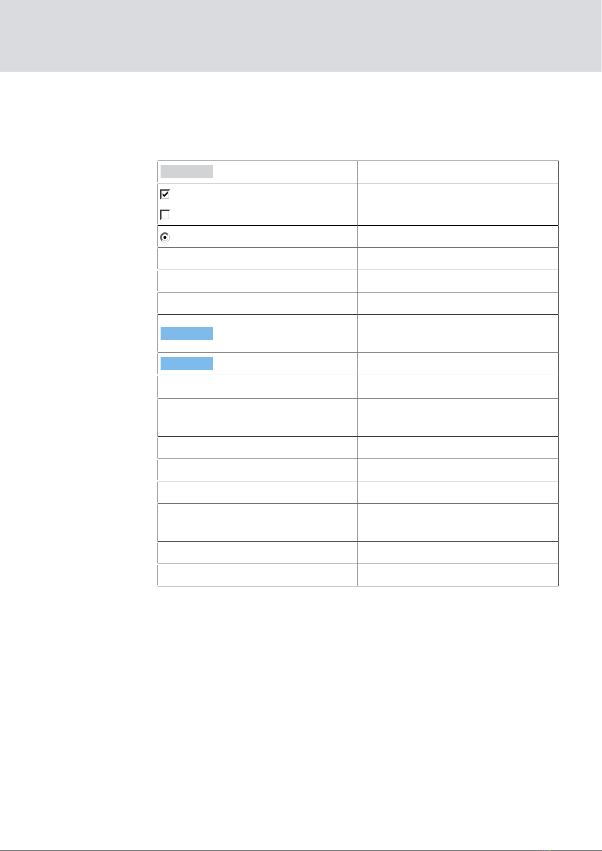
4 Meaning of the text formatting
This documentation uses text formatting and design elements to facilitate
understanding. The table explains the meaning of possible text formatting:
Example button
Example
Example checkbox
Example Option
[Example] Tab
"Example" Name of a displayed window
|Example| Upper programme bar
Example Entry in the expanded upper pro-
gramme bar
Example Context menu entry
▼ Example Name of a drop-down menu
"Example" Selection option in a drop-down
menu
"Example" Area
Example Field
Example
Name of a (Windows) service
Example
Commands (e.g. Windows CMD
commands)
Example Database entry
[Example] MobileKey type selection
SREL, SREL.ADV, SREL.W SREL.G2,
SREL.G2.W, SREL2.G2 (Manual)
4. Meaning of the text formatting
9 / 44
5 General
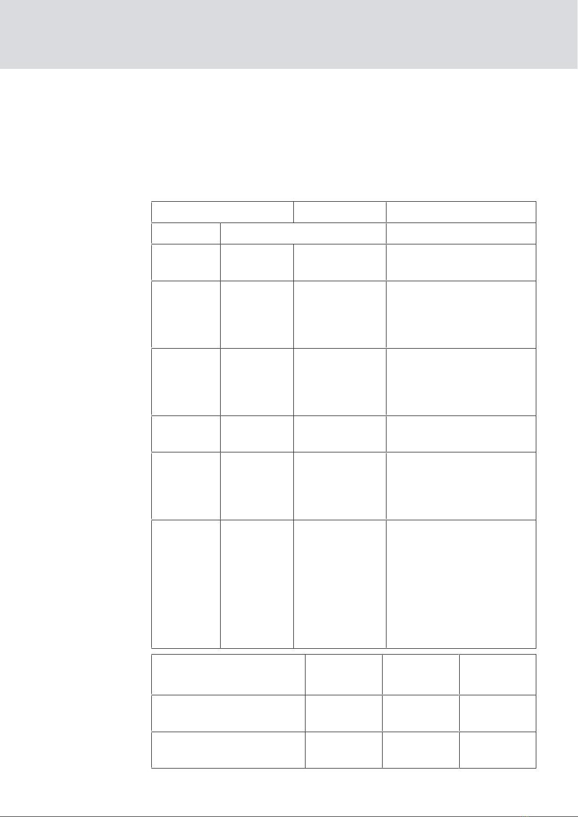
5.1 Versions
SmartRelays are available in an extensive variety of versions for different
product lines. Carefully check which SmartRelay is the right one for your
use before placing an order.
SREL
(black)
SREL2
(white)
G1 G2
SREL SREL.G2 SREL.W.G2 Basic version of SmartRelay
3063.
SREL.ZK SREL.ZK.G2 SREL.W.ZK.G2
As the basic version of
SmartRelay 3063, plus ac-
cess control and time zone
control.
SREL.ADV
As the access control ver-
sion of SmartRelay 3063,
but with additional func-
tions for issuing.
SREL2.G2.W Basic version of SmartRe-
lay2 3063.
SREL2.ZK.G2.W
As the basic version of
SmartRelay2 3063, plus ac-
cess control and time zone
control.
SREL2.ZK.MH.
G2.W
As the access control ver-
sion of SmartRelay2 3063,
but also with support for an
internal MIFARE® card
reader and connection op-
tions for a maximum of
three external MIFARE®
card readers.
SREL SREL
.ZK
SREL
.ADV
Authorised for up to 8,184
transponders XXX
Authorised for up to 64,000
transponders
SREL, SREL.ADV, SREL.W SREL.G2,
SREL.G2.W, SREL2.G2 (Manual)
5. General
10 / 44
Other manuals for SREL
1
This manual suits for next models
5
Table of contents
Other Simons Voss Technologies Switch manuals


