Simphoenix V800 Series User manual

PREFACE
Thanks for choosing V800 Series High Performance Closed-Loop Vector Frequency
Inverter produced by Shenzhen Simphoenix Electric Technology Co, Ltd.
This Manual is the operating manual for V800 series closed-loop vector frequency
inverter. It provides all relevant instructions and precautions for installation, wiring,
functional parameters, daily care and maintenance, fault diagnosis and troubleshooting
of V800 series inverter.
In order to use this product correctly, guarantee product's best performance and ensure
safety of users and equipment, be sure to read this manual carefully before using V800
series inverters. Improper use may cause abnormity and malfunction of the inverter,
reduce its service life and even damage equipments and lead to personal injury and
death, etc.
This user manual is delivered with the device. Please keep it property for future
overhaul and maintenance.
Owing to constant improvement of products, all data may be changed without further
notice.
V800 Series High Performance Closed-Loop Vector Inverter User Manual
Version: V1.1
Revision Date: june. 2018
This Manual is applicable to V6100 and above programs.

CATALOG
1. PRODUCT CONFIRMATION AND OPERATION CAUTIONS...............................................
1.1 PRODUCT CONFIRMATION.........................................................................................................
1.1.1 CONFIRMATION OF FREQUENCY INVERTER BODY AND ACCESSORIES.
1.1.2 NAMEPLATE OF FREQUENCY INVERTER..............................................................
1.2 SAFETY CAUTIONS.......................................................................................................................
1.2.1 NOTICES DURING INSTALLATION.............................................................................
1.2.2 SAFETY CAUTION FOR WIRING................................................................................
1.2.3 SAFETY CAUTION FOR RUNNING OPERATION...................................................
1.2.4 SAFETY CAUTION FOR MAINTENANCE CHECK..................................................
1.3 KNOWLEDGE ON OPERATION..................................................................................................
1.3.1 APPLICATION KNOWLEDGE OF DRIVING GENERAL MOTOR.........................
1.3.2 APPLICATION KNOWLEDGE OF DRIVING SPECIAL MOTOR...........................
1.3.3 AMBIENT ENVIRONMENT.............................................................................................
1.3.4 CONNECTION KNOWLEDGE OF PERIPHERAL EQUIPMENT...........................
1.3.5 TRANSPORTATION AND STORAGE..........................................................................
1.4 ABANDON CAUTION......................................................................................................................
1.5 OTHER CAUTIONS.........................................................................................................................
2. PRODUCTION INTRODUCTION................................................................................................
2.1 INVERTER MODEL..........................................................................................................................
2.2 PRODUCT APPEARANCE.............................................................................................................
2.3 MODEL TABLE..................................................................................................................................
2.4 PRODUCT TECHNICAL INDEX AND SPECIFICATIONS......................................................
3. INSTALLATION OF FREQUENCY INVERTER........................................................................
3.1 INSTALLATION OF FREQUENCY INVERTER.........................................................................
3.1.1 MOUNTING SURFACE....................................................................................................
3.1.2 INSTALLATION SPACE...................................................................................................
3.1.3 MULTIPLE INSTALLATIONS..........................................................................................
3.2 SIZE AND ASSEMBLY OF OPERATION PANEL......................................................................
3.3 DISASSEMBLY OF TERMINAL COVER.....................................................................................
3.3.1 DISASSEMBLY AND INSTALLATION OF PLASTIC COVER PLATE...................
3.3.2 DISASSEMBLY AND INSTALLATION OF SHEET-METAL COVER PLATE........
3.4 INSTALLATION SIZE OF PANEL..................................................................................................
3.5 DISASSEMBLY AND INSTALLATION OF EXPANSION BOARD..........................................
1
1
1
1
1
2
2
2
3
3
3
3
3
3
4
4
4
5
5
5
7
8
11
11
11
11
11
12
14
14
14
15
16

3.6 INSTALLATION AND DISASSEMBLY OF FUNCTION BOARD............................................
3.7 INSTALLATION SIZE OF FREQUENCY INVERTER...............................................................
4. WIRING OF FREQUENCY INVERTER......................................................................................
4.1 CAUTIONS OF WIRING.................................................................................................................
4.2 CONNECTION OF OPTIONAL FITTINGS AND FREQUENCY INVERTER......................
4.3 WIRING OF CONTROL TERMINAL.............................................................................................
4.3.1 WIRING OF CONTROL PANEL STANDARD TERMINAL CON1 AND CON2....
4.3.2 FUNCTION DESCRIPTION OF CONTROL TERMINAL..........................................
4.3.3 CAUTIONS TO THE WIRING OF CONTROL TERMINAL.......................................
4.3.4 DESCRIPTION OF DIP SWITCH ON CONTROL PANEL.......................................
4.4 WIRING OF MAJOR LOOP TERMINAL......................................................................................
4.4.1 TERMINAL FUNCTIONS.................................................................................................
4.4.2 WIRING OF MAJOR LOOP TERMINAL AND TERMINAL BLOCKS.....................
4.5 WIRING CONNECTION OF BASIC OPERATION....................................................................
5. OPERATION AND SIMPLE RUNNING OF FREQUENCY INVERTER................................
5.1 BASIC FUNCTION OF PANEL......................................................................................................
5.2 BASIC FUNCTIONS AND OPERATING METHODS OF PANEL..........................................
5.2.1 BASIC FUNCTIONS OF PANEL....................................................................................
5.2.2 OPERATING METHODS OF PANEL............................................................................
5.3 SIMPLE RUNNING OF FREQUENCY INVERTER..................................................................
5.3.1 OPERATION PROCESS..................................................................................................
5.3.2 INITIAL SETTING OF FREQUENCY INVERTER......................................................
5.3.3 SIMPLE OPERATION.......................................................................................................
5.3.3.1 SVC (NON-INDUCTIVE VECTOR) OPERATION.......................................
5.3.3.2 VC (INDUCTIVE VECTOR) OPERATION....................................................
6. FUNCTIONAL PARAMETER TABLE.........................................................................................
6.1 EXPLANATIONS...............................................................................................................................
6.2 FUNCTION TABLE...........................................................................................................................
6.2.1 SYSTEM MANAGEMENT PARAMETER.....................................................................
6.2.2 SELECTION OF RUNNING COMMANDS..................................................................
6.2.3 FREQUENCY SETTING..................................................................................................
6.2.4 CONTROL COMMAND SOURCE.................................................................................
6.2.5 START AND STOP............................................................................................................
6.2.6 ACCELERATION AND DECELERATION CHARACTERISTICS
PARAMETERS.............................................................................................................................
6.2.7 CARRIER FREQUENCY.................................................................................................
16
17
20
20
21
24
24
24
25
25
26
26
26
30
31
31
32
32
34
36
36
38
39
39
40
41
41
41
41
44
45
46
46
48
48

6.2.8 V/F PARAMETERS AND OVERLOAD PROTECTION (MOTOR 1)......................
6.2.9 V/F PARAMETERS AND OVERLOAD PROTECTION (MOTOR 2)......................
6.2.10 STEADY RUNNING........................................................................................................
6.2.11 VECTOR RUNNING PARAMETERS (MOTOR 1)...................................................
6.2.12 VECTOR RUNNING PARAMETERS (MOTOR 2)...................................................
6.2.13 PARAMETER MEASUREMENT AND PRE-EXCITATION.....................................
6.2.14 MULTIFUNCTIONAL INPUT TERMINAL...................................................................
6.2.15 MULTIFUNCTIONAL OUTPUT TERMINAL..............................................................
6.2.16 PULSE INPUT..................................................................................................................
6.2.17 PULSE OUT......................................................................................................................
6.2.18 ANALOG INPUT..............................................................................................................
6.2.19 ANALOG INPUT CURVE CORRECTION..................................................................
6.2.20 ANALOG OUTPUT..........................................................................................................
6.2.21 ANALOG INPUT POWER FAILURE DETECTION..................................................
6.2.22 VIRTUAL ANALOG INPUT............................................................................................
6.2.23 HOPPING FREQUENCY...............................................................................................
6.2.24 BUILT-IN AUXILIARY TIMER........................................................................................
6.2.25 BUILT-IN AUXILIARY COUNTER................................................................................
6.2.26 AUXILIARY FUNCTIONS..............................................................................................
6.2.27 MOTOR TEMPERATURE DETECTION....................................................................
6.2.28 MULTI-STAGE FREQUENCY SETTING...................................................................
6.2.29 SIMPLE PROGRAMMABLE MULTI-STAGE OPERATION...................................
6.2.30 SWING FREQUENCY OPERATION..........................................................................
6.2.31 PROCESS PID (4MS CONTROL CYCLE)................................................................
6.2.32 PROCESS PID MULTI-STAGE SETTING.................................................................
6.2.33 PROCESS PID SLEEP FUNCTION...........................................................................
6.2.34 REVOLUTION SETTING AND FEEDBACK..............................................................
6.2.35 REVOLUTION CLOSED-LOOP PARAMETER........................................................
6.2.36 PROTECTION PARAMETER.......................................................................................
6.2.37 TORQUE CONTROL......................................................................................................
6.2.38 COMPENSATION PID (RUNNING CYCLE: 1MS)..................................................
6.2.39 COMPENSATION PID CONTROLLER PARAMETER SELECTION..................
6.2.40 MODBUS FIELDBUS (STANDARD EXPANSION CARD CONFIGURATION).
6.2.41 MAPPING ACCESS PARAMETER.............................................................................
6.2.42 COMMUNICATION LINKAGE SYNCHRONOUS CONTROL...............................
6.2.43 EXPANSION MULTIFUNCTIONAL INPUT TERMINAL..........................................
49
49
50
51
52
53
53
54
55
55
56
56
57
58
59
59
60
62
63
64
64
65
66
67
69
70
70
71
72
73
74
76
77
78
78
79

6.2.44 EXPANSION MULTIFUNCTIONAL OUTPUT TERMINAL.....................................
6.2.45 SERVOCONTROL AND SCALE POSITIONING......................................................
6.2.46 VIRTUAL INPUT AND OUTPUT...................................................................................
6.2.47 PROTECTION FUNCTION CONFIGURATION PARAMETER.............................
6.2.48 CORRECTION PARAMETER.......................................................................................
6.2.49 SPECIAL FUNCTIONAL PARAMETERS...................................................................
6.2.50 OTHER CONFIGURATION PARAMETERS..............................................................
6.2.51 HISTORICAL FAULT RECORDING............................................................................
6.2.52 OPERATION STATUS AT THE LAST FAULT............................................................
6.2.53 BASIC STATUS PARAMETER.....................................................................................
6.2.54 AUXILIARY STATUS PARAMETER............................................................................
6.2.55 MODBUS FIELDBUS STATUS PARAMETER (Standard Expansion Card)......
6.2.56 TERMINAL STATUS AND VARIABLE.........................................................................
6.2.57 COUNTER TIMER VALUE............................................................................................
6.2.58 SPINDLE CONTROL AND SCALE POSITIONING STATUS PARAMETER......
6.2.59 EQUIPMENT INFORMATION.......................................................................................
7. DESCRIPTION OF SPECIFIC FUNCTIONS...............................................................................
7.1 SYSTEM MANAGEMENT (GROUP F0.0)....................................................................................
7.2 RUNNING COMMAND SELECTION (GROUP F0.1).................................................................
7.3 FREQUENCY SETUP (GROUP F0.2)........................................................................................
7.4 CONTROL COMMAND SOURCE (GROUP F0.3)...................................................................
7.5 START AND STOP (GROUP F0.4)..............................................................................................
7.6 ACCEL AND DECEL CHARACTERISTICS (GROUP F1.0)...................................................
7.7 CARRIER FREQUENCY (GROUP F1.1)...................................................................................
7.8 V/F PARAMETERS AND OVERLOAD PROTECTION (MOTOR 1) (GROUP F1.2)........
7.9 V/F PARAMETERS AND OVERLOAD PROTECTION (MOTOR 2) (GROUP F1.3)........
7.10 STEADY RUNNING (GROUP F1.4)..........................................................................................
7.11 VECTOR RUNNING PARAMETERS (MOTOR 1) (GROUP F2.0).....................................
7.12 PARAMETER MEASUREMENT AND PRE-EXCITATION (GROUP F2.2).......................
7.13 MULTIFUNCTIONAL INPUT TERMINAL (GROUP F3.0).....................................................
7.14 MULTIFUNCTIONAL OUTPUT TERMINAL (GROUP F3.1)................................................
7.15 PULSE INPUT (GROUP F3.2)...................................................................................................
7.16 PULSE OUTPUT (GROUP F3.3)...............................................................................................
7.17 ANALOG INPUT (GROUP F4.0)................................................................................................
7.18 ANALOG INPUT CURVE CORRECTION (GROUP F4.1)...................................................
7.19 ANALOG OUTPUT (GROUP F4.2)...........................................................................................
80
80
82
84
85
85
86
87
87
88
90
90
91
91
92
92
97
97
105
111
114
116
123
125
126
128
128
132
133
134
142
145
146
147
148
148

7.20 ANALOG INPUT WIRE-BREAK DETECTION (GROUP F4.3)...........................................
7.21 HOPPING FREQUENCY (GROUP F5.0)................................................................................
7.22 BUILT-IN AUXILIARY TIMER (GROUP F5.1).........................................................................
7.22.1 BASIC FUNCTIONS OF THE TIMER........................................................................
7.22.2 TRIGGER AND GATE CONTROL FUNCTION SETTING OF TIMER...............
7.22.3 CLOCK CONCATENATION FUNCTION SETTING OF TIMER..........................
7.22.4 CONCATENATION TRIGGER FUNCTION SETTING OF TIMER......................
7.23 BUILT-IN AUXILIARY COUNTER (GROUP F5.2).................................................................
7.24 AUXILIARY FUNCTIONS (GROUP F5.3)................................................................................
7.25 MOTOR TEMPERATURE DETECTION (GROUP F5.4)......................................................
7.26 MULTI-STAGE FREQUENCY SETTING (GROUP F6.0).....................................................
7.27 SIMPLE PROGRAMMABLE MULTI-STAGE OPERATION (GROUP F6.1)....................
7.28 SWING FREQUENCY OPERATION (GROUP F6.2)............................................................
7.29 PROCESS PID (4MS CONTROL CYCLE) (GROUP F7.0).................................................
7.30 PROCESS PID MULTI-STAGE SETTING (GROUP F7.1)..................................................
7.31 PROCESS PID SLEEPING FUNCTION (GROUP F7.2).....................................................
7.32 REVOLUTION SETTING AND FEEDBACK (GROUP F8.0)...............................................
7.33 REVOLUTION CLOSED-LOOP PARAMETER (GROUP F8.1).........................................
7.34 PROTECTIVE PARAMETERS (GROUP F8.2)......................................................................
7.35 TORQUE CONTROL (GROUP F8.3).......................................................................................
7.36 COMPENSATION PID (1MS CONTROL CYCLE) (GROUP F9.0)....................................
7.37 PARAMETER SELECTION OF COMPENSATION PID CONTROLLER.........................
7.38 MODBUS FIELDBUS (GROUP FA.0)......................................................................................
7.39 MAPPING PARAMETER ACCESS (GROUP FA.1)..............................................................
7.40 COMMUNICATION LINKAGE SYNCHRONOUS CONTROL (GROUP FA.2)................
7.41 EXPANSION MULTIFUNCTIONAL INPUT TERMINAL (GROUP FB.0 AND FB.1).......
7.42 SERVO CONTROL AND SCALE POSITIONING (GROUP FB.2).....................................
7.43 VIRTUAL INPUT AND OUTPUT (GROUP FF.0)....................................................................
7.44 PROTECTING FUNCTION CONFIGURATION PARAMETERS (GROUP FF.1)...........
7.45 CORRECTION PARAMETERS (GROUP FF.2).....................................................................
7.46 SPECIAL FUNCTIONAL PARAMETERS (GROUP FF.3)....................................................
7.47 OTHER CONFIGURATION PARAMETERS (GROUP FF.4)...............................................
8. WARNING, ALARM DIAGNOSIS AND COUNTER MEASURES........................................
8.1 TROUBLESHOOTING WITH WARNING OR ALARM DISPLAY..........................................
8.1.1 ALARM DISPLAY AND TROUBLESHOOTING.........................................................
8.1.2 WARNING DISPLAY AND TROUBLESHOOTING...................................................
150
150
151
151
152
152
153
153
154
157
159
163
163
166
171
171
171
174
175
176
179
180
181
181
182
184
184
187
188
188
190
190
192
192
192
197

8.2 ABNORMAL OPERATION WITHOUT PROMPTS AND THE SOLUTIONS......................
8.3 FAILURES IN SETTING OPERATION OF FREQUENCY INVERTER...............................
8.4 INQUIRY FOR FAILURE RECORD.............................................................................................
8.5 RESET OF WARNING OR ALARM FAILURE..........................................................................
9. MAINTENANCE............................................................................................................................
9.1 ROUTINE MAINTENANCE...........................................................................................................
9.2 INSPECTION AND DISPLACEMENT OF THE VULNERABLE COMPONENTS............
9.2.1 FILTER CAPACITOR......................................................................................................
9.2.2 COOLING FAN..................................................................................................................
9.3 STORAGE.........................................................................................................................................
9.4 WARRANTY......................................................................................................................................
10. EXAMPLE OF USAGE..............................................................................................................
10.1 ENERGY-SAVING TRANSFORMATION OF ESCALATORS.............................................
10.1.1 SCHEME DESCRIPTION.............................................................................................
10.1.2 WIRING DIAGRAM........................................................................................................
10.2 MAKE SIMPLE TENSION CLOSED-LOOP CONTROL WITH OFFSET PID.................
10.2.1 DIAGRAM OF CONSTANT TENSION CONTROL.................................................
10.2.2 DIAGRAM OF CONTROL STRUCTURE.................................................................
10.2.3 CONFIGURATION.........................................................................................................
10.2.4 WIRING DIAGRAM........................................................................................................
10.3 APPLICATION IN MECHANICAL FACTORY..........................................................................
10.3.1 CONFIGURATION.........................................................................................................
10.3.2 EXTERNAL CIRCUIT WIRING DIAGRAM...............................................................
10.4 MULTI-PID SETUP, MULTI-PART PID SETUP, FORM A MULTI- STEP PIDSETUP....
10.4.1 PARAMETER SETUP...................................................................................................
10.4.2 DIAGRAM OF STEP PID VALUE GIVEN.................................................................
11. DESCRIPTION OF COMMUNICATION PROTOCOL..........................................................
11.1 MODBUS PROTOCOL DESCRIPTION...................................................................................
11.1.1 PROTOCOL OVERVIEW.............................................................................................
11.1.2 INTERFACE AND TRANSMISSION METHOD.......................................................
11.1.3 DATA STRUCTURE.......................................................................................................
11.1.4 PARAMETER CONFIGURATION FOR FREQUENCY INVERTERS................
11.1.5 BRIEF INTRODUCTION OF FUNCTIONS..............................................................
11.1.6 ACCESS ADDRESS SUMMARY................................................................................
11.1.7 DETAILED MODBUS ADDRESS-FINDING DISTRIBUTION..............................
11.1.8 EXAMPLES.....................................................................................................................
200
203
204
205
206
206
207
207
207
208
208
209
209
209
210
210
211
211
211
212
213
213
213
214
214
214
215
215
215
215
215
215
216
216
217
222

12. EMC...............................................................................................................................................
12.1 CE.....................................................................................................................................................
12.2 DEFINITION....................................................................................................................................
12.3 OBEY STANDARD ORDER........................................................................................................
12.3.1 OBEY EMC ORDER......................................................................................................
12.3.2 OBEY LVD ORDER.......................................................................................................
12.4 GUIDANCE OF EMC EXTERNAL ACCESSORIES INSTALLATION AND Selection....
12.4.1 NOTICE OF I EMI INPUT FILTER INSTALLATION...............................................
12.4.2 DC REACTOR.................................................................................................................
12.4.3 FU INPUT REACTOR...................................................................................................
12.4.4 AC OUTPUT REACTOR...............................................................................................
12.5 SHIELDED CABLE.......................................................................................................................
12.6 CABLE WIRING REQUIREMENTS..........................................................................................
12.7 LEAKAGE CURRENT RESPONSE REQUIREMENTS.......................................................
12.8 COMMON EMC INTERFERENCE PROBLEM AND SOLUTION......................................
13. ACCESSORIES...........................................................................................................................
13.1 BRAKE ASSEMBLY......................................................................................................................
13.1.1 MODEL OF BRAKE UNIT............................................................................................
131.2 GUIDE OF BRAKE RESISTANCE SELECTION .....................................................
13.1.3 APPEARANCE OF BRAKE UNIT ...............................................................................
13.1.4 INSTALLATION SIZE OF BRAKE UNIT...................................................................
13.1.5SINGLE BRAKE UNIT AND INVERTER REFERENCE WIRING SKETCH......
13.1.6 WIRING PRECAUTIONS.............................................................................................
13.2 I/O EXPANSION CARD (STANDARD TYPE: DEC350VS, PN: 050M008003000)........
13.3 PG EXPANSION CARD (STANDARD DEB3PG12VA, PN: 050M009012002)...............
13.4 INTRODUCTION OF LCD OPERATING PANEL...................................................................
13.4.1 OUTSIDE VIEW OF LCD OPERATING PANEL.....................................................
13.4.2 LED OPERATION PANEL............................................................................................
13.4.3 FUNCTION OF KEYS...................................................................................................
224
224
224
224
224
224
225
225
225
226
227
229
229
230
231
232
232
232
232
234
234
235
235
236
237
238
238
238
238
Product Confirmation And Operation Cautions
1
V800 Series High Performance Closed-Loop Vector Inverter User Manual
1. PRODUCT CONFIRMATION AND OPERATION
CAUTIONS
1.1 PRODUCT CONFIRMATION
Check the outer packing carefully to see if there is any damage after the arrival of the goods; if there is a
label on the outer packing, please confirm the model and specification of it to see if they are in accordance
with your order. If any damage or discrepancy is found, please contact the supplier promptly for solution.
1.1.1 CONFIRMATION OF FREQUENCY INVERTER BODY AND ACCESSORIES
Confirm the frequency inverter body and accessories carefully when unpacking, to see if there is any
damage during the transit, and if the parts and components are damaged or dropped, and if there is the
frequency inverter entity and the following accessories:
Operation instruction;
Certification;
Product list;
Other ordered accessories
If there is any omission or damage, please contract the supplier promptly for solution.
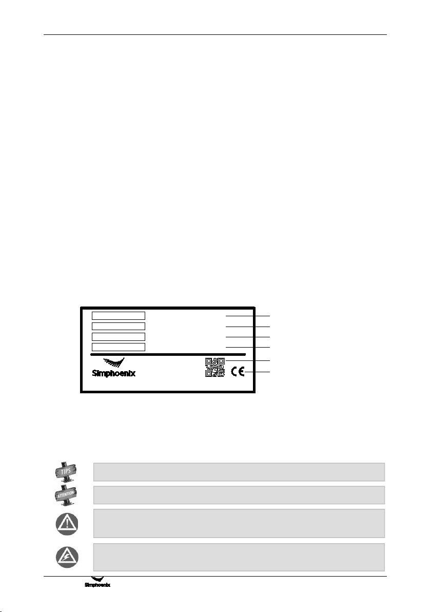
1.1.2 NAMEPLATE OF FREQUENCY INVERTER
On the frequency inverter, there is a nameplate marked with model, rated parameters, product serial-number
and bar code of frequency inverter. The content of nameplate is shown as below:
1.2 SAFETY CAUTIONS
Read this instruction carefully prior to installation, wiring, operation and maintenance, to ensure proper
operation of this product.
"Tips", "Attention", " Warning " and " Danger " in this operation manual are defined as follow:
Warning: Without operation according to the requirements, moderate injuries or minor
injuries of personnel and material loss may be caused.
Danger: Without operation according to the requirements, serious damage to the
equipment or personnel injuries may be caused.
Attention: Matter requires attention during operation.
Tips: Tips for some useful information.
Shenzhen Simphoenix Electric Technology Co.,Ltd
V800-4T0011G/4T0015P
3PH 380V 50/60Hz
2.0KVA 3.0A/2.4KVA 3.7A
XXXXXXXXXX
TYPE
SOURCE
OUTPUT
SERIAL No.
MADE IN CHINA
Model of frequency inverter
Rated input voltage number of phase,
voltage and frequency
Rated output capability and current
Product serial-number
QR code
Certification logos

2
Product Confirmation And Operation Cautions
V800 Series High Performance Closed-Loop Vector Inverter User Manual
1.2.1 NOTICES DURING INSTALLATION
1. The frequency inverter shall not be installed on combustibles, in case of the risk of fire.
2. The frequency inverter shall not be installed at places with direct sunlight, in case of danger.
3. The frequency inverter of this series shall not be installed in the environment of explosive gases, in case of
the danger of explosion.
4. Do not install the Frequency inverter if damaged or lf components are missing. Installation may lead to
personal injury, fire or other accidents.
5. Do not remove or modify the frequency inverter without authorization.
6. No foreign matter is allowed to be dropped into the frequency inverter, in case of breakdown of the
frequency inverter.
7. During installation, the frequency inverter shall be installed at the place able to bear its weight; otherwise,
it may fall down.
1.2.2 SAFETY CAUTION FOR WIRING
1. Please authorize the professional staff to conduct wiring. If the wiring operation is not proper, it may
damage to the equipment and the individuals.
2. Please start to wire after the panel digital tube of frequency inverter is out for ten minutes, otherwise, there
can be electric shock risk.
3. The grounding terminal of frequency inverter must be reliably grounded; otherwise, there can be electric
shock risk.
4. Connection of AC power onto the output terminals U, V and W of frequency inverter, will damage the
frequency inverter, and may lead to personal injury.
5. Confirm that the input voltage and frequency converter are in consistent with rated voltage value;
otherwise, the frequency inverter may be damaged.
6. Confirm that the motor and frequency converter are adaptive with each other, otherwise, the motor can be
damaged or frequency converter protection can be caused.
7. Brake resistor cannot be connected onto the (+), (-) of DC bus directly; otherwise, there can be fire risk.
1.2.3 SAFETY CAUTION FOR RUNNING OPERATION
1. Please do not operate the switch with wet hand; otherwise, there can be electric shock.
2. Please install the front cover prior to plugging in, and shall not demount the cover while power is on,
otherwise, here can be electric shock.
3. During the frequency converter is with power on, even the motor is stopped, do not touch the terminals of
frequency converter, otherwise, here can be electric shock.
4. If you apply the function of restart, do not approach the load equipment, for it may restart suddenly after
alarm removed, otherwise, personal injuries may caused. Please set the system as ensuring personal and
property safety even when restarting.
5. Please set additional emergency stop switch, otherwise, personal injuries may be caused.
6. The temperature of cooling fin and direct current reactor can be very high, therefore, do not touch them, in
case of the danger of burns.

Product Confirmation And Operation Cautions
3
V800 Series High Performance Closed-Loop Vector Inverter User Manual
1.2.4 SAFETY CAUTION FOR MAINTENANCE CHECK
1. Maintenance operations of overhaul and device replacement only can be done by trained professional
maintenance staff. During operation, insulation protection tools shall be applied. It is strictly prohibited to
leave thrum and metal in the machine. Otherwise, there can be dangers of electric shock, fire, and
personal and property damage.
2. After replacement of control board, corresponding parameters must be set before operation; otherwise,
there can be danger of property damage.
1.3 KNOWLEDGE ON OPERATION
1.3.1 APPLICATION KNOWLEDGE OF DRIVING GENERAL MOTOR
1. The temperature when driving general motor applied with frequency converter can be a little higher than
that of industrial frequency power. With long-term operation at low speed, the operation life of motor can
be affected due to the poorer heat dissipation effect. In this case, special frequency converter shall be
selected or lighten the motor load.
2. If when the equipment is installed with frequency converter drive, sometimes, there can be resonance due
to the natural vibration frequency of mechanical system, please consider about applying flexible coupling
and insulation rubber, or applying the function of hopping frequency of the frequency converter, to avoid
the resonance point for operation.
3. There can be larger noise when driving general motor applied with frequency converter than that of
industrial frequency power. In order to reduce the noise, the carrier frequency of frequency converter can
be increased properly.
1.3.2 APPLICATION KNOWLEDGE OF DRIVING SPECIAL MOTOR
1. For high-speed motor, if the set frequency of frequency converter is above 120Hz, please conduct
combination test with motor, to make sure it can be operated safely.
2. For synchronous motor, there must be correspondences according to the types of motor. Please contract
the manufacturer for consultation.
3. Operation of single-phase motor is not applied with frequency converter. Even when input with single
phase, there is three-phase output, please apply with three-phase motor.
1.3.3 AMBIENT ENVIRONMENT
Application shall be applied in the indoor range with environment temperature of -10 to +45°C, humidity
around below 95% (without condensation of moisture), no dust, no direct sunlight, no corrosive gas, no
combustible gas, no oil mist, no steam, no water or floating fiber or mental particles; if there is special
requirements of clients, please contract the manufacturer for consultation.
1.3.4 CONNECTION KNOWLEDGE OF PERIPHERAL EQUIPMENT
1. For the protection of wirings, please configure breaker for wirings on the input side of frequency converter.
Please do not apply device with larger capacity than recommendation.
2. If it needs to switch to industrial frequency power and others, when installing electromagnetic contactor on
the output side of frequency converter, please switch after frequency converter and motor stop running.
3. When applying with motor thermal relay, if the wiring of motor is too long, sometimes it is affected with the
high-frequency current flowing through capacitance distributed with wiring, current below the set value of
thermal relay may also cause trip. In this case, please lower the carrier frequency, or apply with output
filter.
4. For noise interference, connection filter, magnet ring and shielded wire can be applied as corresponding
measures.

4
Product Confirmation And Operation Cautions
V800 Series High Performance Closed-Loop Vector Inverter User Manual
1.3.5 TRANSPORTATION AND STORAGE
1. During product handling, please capture the both sides of the bottom of the entity, rather than the cover or
parts only.
2. Please do not make the parts of plastic excessive forced, otherwise, there can be falling down or damage.
3. When it is for temporary storage and long-term storage, pay attention to the followings:
Try to be packaged in the packing case of our company as the original package for storage.
Long-term of storage will lead to the characteristics of electrolytic capacitor worsen, therefore, it shall
be powered on every half year at least, and with conduction time more than half an hour, and the input
voltage must be risen to the rated value gradually with voltage regulator.
1.4 ABANDON CAUTION
1. Explosion of the electrolytic capacitor: Electrolytic capacitor in the frequency converter may cause
explosion while burning.
2. Waste gas of plastic burning: Harmful and toxic gas may be produces while burning the plastic and rubber
product of the frequency converter.
3. Disposal methods: Please deal with the frequency converter as industrial waste.
1.5 OTHER CAUTIONS
1. This product shall not be applied for life support device and other application concerning directly with
human body safety, otherwise, there can be accident.
2. If serious accident or serious losses caused due to the failure of this product, please install safety device
for this product, otherwise, there can be accident.
1.6 INCASE OF DAMAGE
1. during the operation process,please observe the procedure of antistatic regulation(ESD,otherwise the
static electricity might cause damage of the internal components.
2. Do not allowed to do withstand voltage test with any part of the inverter because lots of precision devices
are used in the inverter and that might cause performance disability even inverter failure.

V800 Series High Performance Closed-Loop Vector Inverter User Manual
Product Introduction
5
2. PRODUCTION INTRODUCTION
2.1INVERTER MODEL
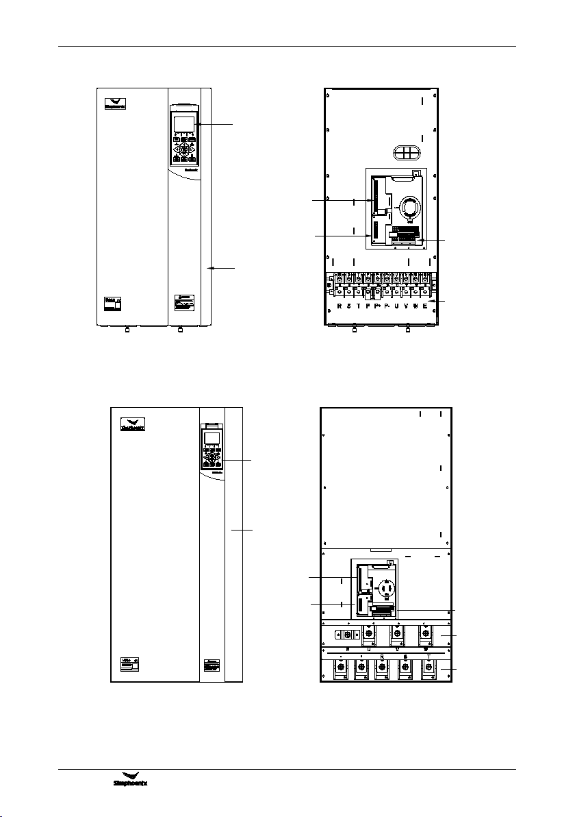
2.2 PRODUCT APPEARANCE
Appearance of Category ⅡApplicable for:V800-4T0040G/4T0055P ~ V800-4T0300G/4T0370P
Appearance of Category ⅢApplicable for:V800-4T0370G/4T0450P ~ V800-4T1320G/4T1600P
Wiring entrace of extension loopr
Plugboard
Fan
Wiring entrace of main loop
Lower cover
Radiator
Upper housing
Operating panel
Function expansion card
Port of operating panel
Expansion loop terminal
Major loop terminal
Port of remote operating panel
Crystal connector position
(remote operation)
Major loop terminal
Control loop terminal
Port of operating panel
Upper cover
Wiring entrace of extension loopr
Wiring entrace of control loop
Plugboard
Wiring entrace of main loop
Lower cover
Lower housing
Upper housing
Operating panel
6
Product Introduction
V800 Series High Performance Closed-Loop Vector Inverter User Manual
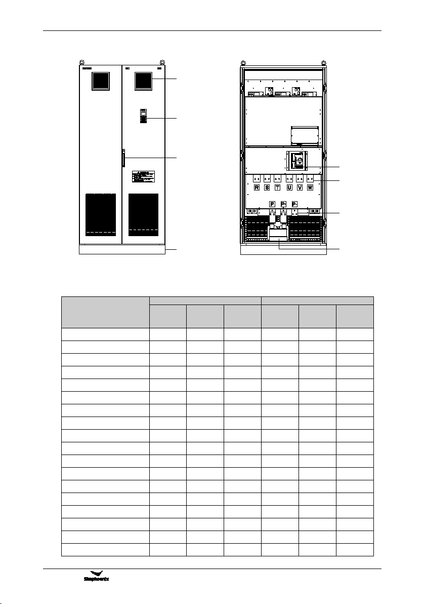
Appearance of Category ⅣApplicable for: V800-4T1600G/4T1850P ~ V800-4T3150G/4T3500P
Operating panel
Control loop
terminal
Major loop
terminal
Major loop
terminal
Extension loop
terminal 1
Extension loop
terminal 2
Upper cover
Appearance of Category ⅤApplicable forV800-4T3500G/4T4000P ~ V800-4T8000G/4T9000P
Operating panel
Upper cover
4T0450G/4T0550P
62.5KVA 95A/72.7KVA 115A
Extension loop
terminal 2
Extension loop
terminal 1 Control loop
terminal
Major loop
terminal
V800 Series High Performance Closed-Loop Vector Inverter User Manual
Product Introduction
7
DC Reactor
Operating
panel
Ventilation
window
Control loop terminal
Major loop terminal
Major loop terminal
Lock
Foundation
2.3 MODEL TABLE
Model
Variable Torque Load
Constant Torque Load
Rated
capacity
(KVA)
Rated
current
(A)
Motor
power
(KW)
Rated
capacity
(KVA)
Rated
current
(A)
Motor
power
(KW)
V800-4T0011G/4T0015P
2.0
3.0
1.1
2.4
3.7
1.5
V800-4T0015G/4T0022P
2.4
3.7
1.5
3.6
5.5
2.2
V800-4T0022G/4T0030P
3.6
5.5
2.2
4.9
7.5
3.0
V800-4T0030G/4T0040P
4.9
7.5
3.0
6.3
9.5
4.0
V800-4T0040G/4T0055P
6.3
9.5
4.0
8.6
13.0
5.5
V800-4T0055G/4T0075P
8.6
13.0
5.5
11.2
17.0
7.5
V800-4T0075G/4T0090P
11.2
17.0
7.5
13.8
21
9.0
V800-4T0090G/4T0110P
13.8
21
9.0
16.5
25
11
V800-4T0110G/4T0150P
16.5
25
11
21.7
33
15
V800-4T0150G/4T0185P
21.7
33
15
25.7
39
18.5
V800-4T0185G/4T0220P
25.7
39
18.5
29.6
45
22
V800-4T0220G/4T0300P
29.6
45
22
39.5
60
30
V800-4T0300G/4T0370P
39.5
60
30
49.4
75
37
V800-4T0370G/4T0450P
49.4
75
37
62.5
95
45
V800-4T0450G/4T0550P
62.5
95
45
75.7
115
55
V800-4T0550G/4T0750P
75.7
115
55
98.7
150
75
V800-4T0750G/4T0900P
98.7
150
75
116
176
90
V800-4T0900G/4T1100P
116
176
90
138
210
110
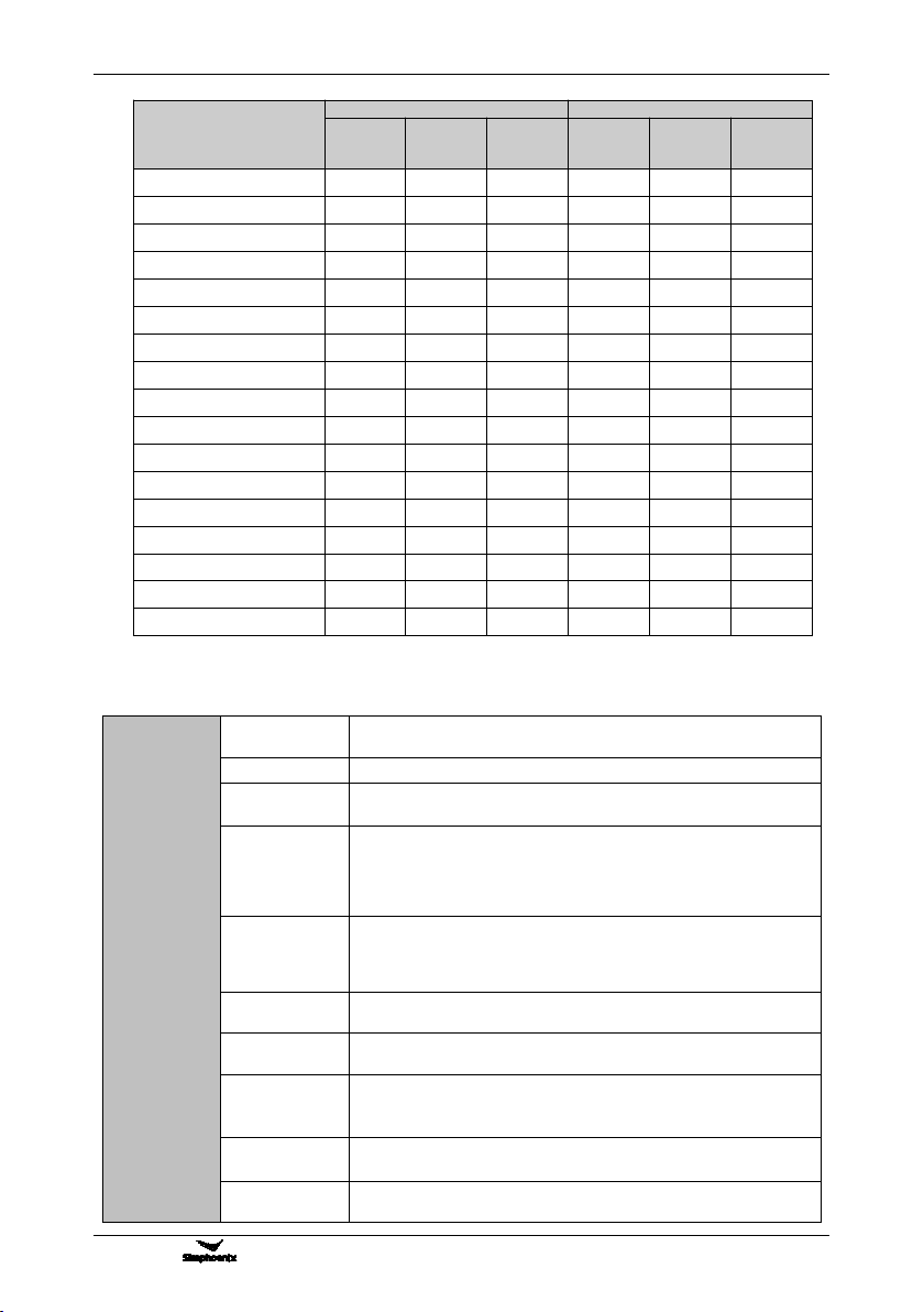
8
Product Introduction
V800 Series High Performance Closed-Loop Vector Inverter User Manual
Model
Variable Torque Load
Constant Torque Load
Rated
capacity
(KVA)
Rated
current
(A)
Motor
power
(KW)
Rated
capacity
(KVA)
Rated
current
(A)
Motor
power
(KW)
V800-4T1100G/4T1320P
138
210
110
171
260
132
V800-4T1320G/4T1600P
171
260
132
204
310
160
V800-4T1600G/4T1850P
204
310
160
237
360
185
V800-4T1850G/4T2000P
237
360
185
253
385
200
V800-4T2000G/4T2200P
253
385
200
276
420
220
V800-4T2200G/4T2500P
276
420
220
313
475
250
V800-4T2500G/4T2800P
313
475
250
352
535
280
V800-4T2800G/4T3150P
352
535
280
395
600
315
V800-4T3150G/4T3500P
395
600
315
424
645
350
V800-4T3500G/4T4000P
428
650
350
480
730
400
V800-4T4000G/4T4500P
480
730
400
527
800
450
V800-4T4500G/4T5000P
527
800
450
592
900
500
V800-4T5000G/4T5600P
592
900
500
658
1000
560
V800-4T5600G/4T6300P
658
1000
560
737
1120
630
V800-4T6300G/4T7000P
737
1120
630
823
1225
700
V800-4T7000G/4T8000P
823
1225
700
955
1450
800
V800-4T8000G/4T9000P
955
1450
800
1053
1600
900
2.4 PRODUCT TECHNICAL INDEX AND SPECIFICATIONS
Input
Output
Rated voltage
frequency
Three phase(4T# series) 380V 50/60Hz
Output voltage
4T# series: 0~380 V
Output
frequency
Low frequency mode:0.0~300.00Hz;
High frequency mode:0.0~2000.0Hz.
Digital input
V800-4T0030G/4T0040P and power below :Standard configuration:
5-circuit digital input (DI)
V800-4T0040G/4T0055P and power above:Standard configuration:
6-circuit digital input (DI), extensible to 16-circuit (optional extension
components)
Digital output
V800-4T0030G/4T0040P and power below:Standard configuration:
1-circuit digital output (DO)
V800-4T0040G/4T0055P and power above:Standard configuration:
2-circuit digital output (DO)
Pulse in and out
0~100.0KHz pulse input, can receive OC or 0~24V level signal
(optional)
Pulse output
0 -100.0KHz pulse output(optional), PWM output mode can be selected
to extend analog output terminal.
Analog input
Standard configuration: 0~10V voltage intput (AI1);
0~20mA current input (AI2)
Standard IO board: -10V~10V voltage input
Analog output
Two-circuit 0-10V analog output signal
(can be set to 0~10V current output mode)
Contact output
Standard one group of AC 250V/2A normally open and closed contacts,
extensible 1-6 groups normally open and closed contacts

V800 Series High Performance Closed-Loop Vector Inverter User Manual
Product Introduction
9
Control
Characteristics
Control Mode
Closed-loop vector
control
Open-loop vector
control
V/F control
Starting torque
0 speed 200%
0 speed 180%
0 speed 180%
Speed
adjustable range
1 : 1000
1 : 200
1 : 100
Steady speed
precision
±0.02%
±0.2%
±0.5%
Torque control
precision
±5%
±5%
--
Control
Characteristics
Torque response
time
≦5ms
≦25ms
--
Frequency
resolution
Low frequency mode:0.01Hz;
High frequency mode:0.1Hz.
Frequency
precision
Low frequency mode:digital setting--0.01 Hz,
Analog setting - highest frequency ×0.1%
High frequency mode:digital setting--0.1 Hz,
Analog setting - highest frequency ×0.1%
Load capacity
Universal load mode: 110% - long-term; 150% - 60s; 180% -5s
Steady load mode (capacity increase mode): 105% - long-term;
120% - 60 s; 150% - 1 s
Carrier
frequency
Two-phase vector composition:1.5~15.0KHz;
Three-phase vector composition: 1.5 ~ 12.0KHz (HIgh frequency
mode can reach 15KHz)
Deceleration
and acceleration
time
0.01 - 600.00Sec. / 0.01 - 600.0Min.
Magnetic flux
brake
Achieve rapid retarding brake of the motor by increasing the motor's
magnetic flux (30-120% allowed)
DC
brake/band-type
rake
DC brake/band-type brake initial frequency: 0.0 - upper limiting
frequency, brake/band-type brake injection current 0.0 ~ 100.0%
Strike frequency
0.0 ~ 50.00Hz
Typical
Function
Multi-segment
running
16-segment frequency/speed running, independent setting of the
running direction, time and acceleration and deceleration of each
segment; 7-segment process PID setting
Built-in PID
Two built-in PID controller (process PID, compensation PID), can be
either used independently by external equipment or be used to create
complicated internal compensation control.
Wakening and
sleeping
Process PID has simple sleeping and wakening functions.
MODBUS
communication
Standard MODBUS communication protocol (optional) allowing for
flexible parameter reading and mapping
Temperature
detection
Able to receive detecting signals of PT100 or PTC thermo-sensitive
elements, hence allows for over-temperature protection for the motor or
external equipment.
Dynamic braking
(Standard configuration for models below V800-4T0220G/4T0300P)
Actuating voltage: 650~760V, braking ratio: 50~100%
General
Functions
Power cut restart; Fault self-recovery, motor parameter dynamic/static
self-identification. Start enabling, operation enabling, start delay, over
current suppression, over voltage/under voltage suppression, V/F
custom curve, analog input curve correction, line brake detection,
textile machinery disturbance (frequency swing) operation.
Function
Features
Virtual IO
terminal
8-circuit one-to-one virtual output and input terminals, allowing for
complicated engineering onsite application in an easy way.
Position servo
Allows for easy servo control and precision positioning of spindle angle.

10
Product Introduction
V800 Series High Performance Closed-Loop Vector Inverter User Manual
and division
positioning
Communication
linkage
synchronization
Easily allows for synchronized rotation of multiple rotation, and free
selection of linkage balance of multiple machines based on current,
torque and power, and the position synchronized balance function can
ensure zero cumulative error of multi-machine linkage.
Function
Features
Load dynamic
balance
Also allows for dynamic balance of multi-machine load (not limited to
communication linkage) and able to achieve torque motor
characteristics.
Strong starting
torque
For load featuring high inertia and high static friction, super strong
starting torque for certain period can be set.
Setting priority
Users can freely select the priority of various frequency/revolution
setting channel; Suitable for combined application for various
occasions.
Setting
combinations
Up to hundreds of setting combinations of frequency, revolution and
torque.
Compensation
PID
Especially built-in compensation PID, flexibly allowing for tension
control, drawing machine control and other special applications.
Dual motor
parameter
With two sets of asynchronous motor parameters, allowing for motor
switch even in the mode of vector control.
Timer
3 built-in timers: 5 kinds of time, 5 kinds of trigger modes, multiple door
access signals and working modes, and 7 kinds of output signals.
Counter
2 built-in counters: Time margin selection, 4 kinds of trigger modes and
7 kinds of output signal
Macro
parameter
Application macro: Allowing for conveniently setting and partially curing
multiple common group parameters and simplifying parameter setting
for common applications.
System macro: Allowing for conveniently switching equipment’s
working mode, and automatically redefining local parameters.
Parameter
testing
Any un-stored parameter tested on site can be stored with one key or
abandoned and restored to original value.
Parameter
display
Allowing for automatically shielding parameters of unused functional
modules or selectively displaying modified, stored or changed
parameters.
Protection
Function
Power supply
Under voltage protection and three-phase power supply unbalancing
protection
Running
protection
Over current protection, over voltage protection, inverter over
temperature protection, inverter overload protection, motor overload
protection, output phase lack protection, and module drive protection.
Equipment
abnormity
Current detected abnormity, EEPROM memory abnormity, and
abnormal control unit, motor over temperature, MC pull-in fault, and
temperature acquisition loop fault.
Motor
connection
Motor not connected, motor’s three-phased parameters unbalanced
and parameter misidentification.
Extension card
Detect and protect the extension card for compatibility or conflict.
Environment
Installation
environment
Indoor vertical installation, not subjecting to direct sunshine, free of
dust, corrosive and flammable gas, oil mist, vapor and free of drips or
salt.
Altitude
0~1000 m. The output current capability drops by 10% for every rise of
1000 m.
Ambient
temperature
Working ambient temperature: -10°C ~ +40°C
Storage ambient temperature: -20°C ~ +60°C
Humidity
Blow 95%, no condensed water
Vibration
< 20m/s2
Installation Of Frequency Inverter
V800 Series High Performance Closed-Loop Vector Inverter User Manual
11
3. INSTALLATION OF FREQUENCY INVERTER
3.1 INSTALLATION OF FREQUENCY INVERTER
This series of frequency inverters are wall-mounted or cabinet frequency inverters, which should be installed
vertically. In order to be in favor of circulation and heat dissipation, please install the frequency inverter at
indoor place with good ventilation. Please refer to 1.3.3 for installation environment. If there is special
installation requirement from customer, please contact with manufacturer in advance.
3.1.1 MOUNTING SURFACE
Sometimes, the temperature of cooling fin may rise to around 90℃, so please install the mounting surface at
the place which can stand for this temperature rise.
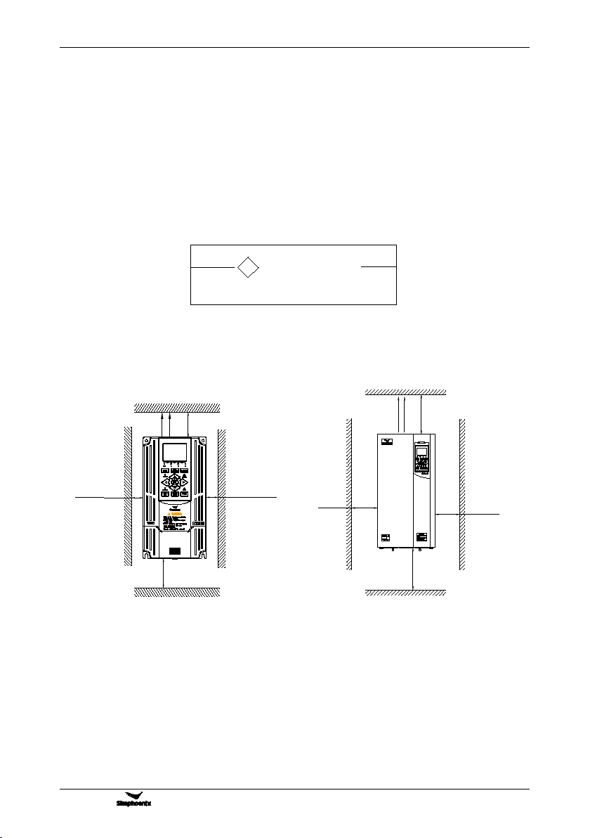
3.1.2 INSTALLATION SPACE
Requirements for installation spacing distance of single frequency inverter are as shown in Figure 3-1-A and
Figure 3-1-B. Reserve enough space around the frequency inverter.
120mm above
Fan
exhaust
120mm above
50mm above
50mm above
150mm above
300mm above
150mm above
300mm above
Fan
exhaust
4T0450G/4T0550P
62.5KVA 95A/72.7KVA 115A
3.1.3 MULTIPLE INSTALLATIONS
If install more than 2 sets of frequency inverters in device or control cabinet, please conduct parallel
installation in principle as shown in Figure 3-3. If there is no choice but vertical installation, please consider
setting partition plate as shown in Figure 3-2, to make no influence on upper frequency inverter from lower
frequency inverter.
Figure 3-1-B Installation spacing
distance (37KW above)
Figure 3-1-A Installation spacing
distance (30KW below)
DANGER
Please install it on flame-retardant object such as metal,
otherwise may cause fire.
!

12
Installation Of Frequency Inverter
V800 Series High Performance Closed-Loop Vector Inverter User Manual
3.2 ASSEMBLY OF OPERATION PANEL
The name of operation panel, model, code and applicable inverter, as follows:
name
Double line LED panel
Double line LCD operation
panel(shuttle type)
Double line LCD standard
operation panel
model
DPNL350EM
DPNL360CB
DPNL360EA
code
050M007033701
050M007360002
050M007360001
Standard
model
Apply to the inverter below
V800-4T0030G/4T0040P
Apply to
V800-4T0040G/4T0055P ~
V800-4T0300G/4T0370P
Apply to the inverter above
V800-4T0370G/4T0450P
appearance
Figure 3-3 Installation sizes of right and
left frequency inverters (4.0KW above)
Baffle plate
Frequency
inverter
Frequency
inverter
Figure 3-2 Installation spacing between
upper and lower frequency inverters
Horizontally close installation is only for 4.0KW below, and -10℃~ 45℃environmental
temperature.
For parallel installation of frequency inverters with different sizes, please carry out
installation after aligning the upper parts of all the frequency inverters, thus to be in favor
of changing cooling fan.
Please don’t install frequency inverter in the environment with tattered cotton yarn and
damp dust which may cause blockage of cooling fin. If necessary to operate in such
environment, please install in the control cabinet which can keep tattered cotton yarn out.
If necessary to install at the place with more than 1000m height above sea level, please
de-rate operation. See 2.4 product technical indexes and specifications for details.
C
A
A
A
A
B
B
Right-and-left space upper-and-lower space
Align the upper part
DD
A-50mm above B-30mm above C-20mm above D-120mm above
This manual suits for next models
35
Table of contents
Other Simphoenix Inverter manuals

Popular Inverter manuals by other brands

ABB
ABB PVI-3.0-TL-OUTD product manual

Solectria Renewables
Solectria Renewables PVI 3000S Installation and operation manual

Whistler
Whistler GO AC PP150AC owner's manual

Mastervolt
Mastervolt AC Master 700 User and installation manual

Potek
Potek PI5000-AP owner's manual

Pioneer
Pioneer WYT-22 Series Installation & user manual


Hoymiles
Hoymiles HA S-3.0LV-EUG1 Quick installation guide

Tektronix
Tektronix AFG1022 Technical reference

Nord Drivesystems
Nord Drivesystems NORDAC PRO SK 500P Manual with installation instructions

CyberPower
CyberPower CPS1000AI user guide

HP
HP 85640A Operating and service manual

Tronic
Tronic TSW 150 A1 operating instructions