2
Included Accessories
1x Installation and Owner’s Manual
1x 16 ft. Communication Cable
SPLIT-TYPE ROOMAIR CONDITIONER
CS78421-548-754
IMPORTANTNOTE:
Read this manual carefully before installing
or operating your new air conditioning
unit. Make sure to save this manual for
future reference.
Installation and
Owner’s Manual
Page 7
Name
Appearance
1x 16 ft. Insulated Copper Pipe
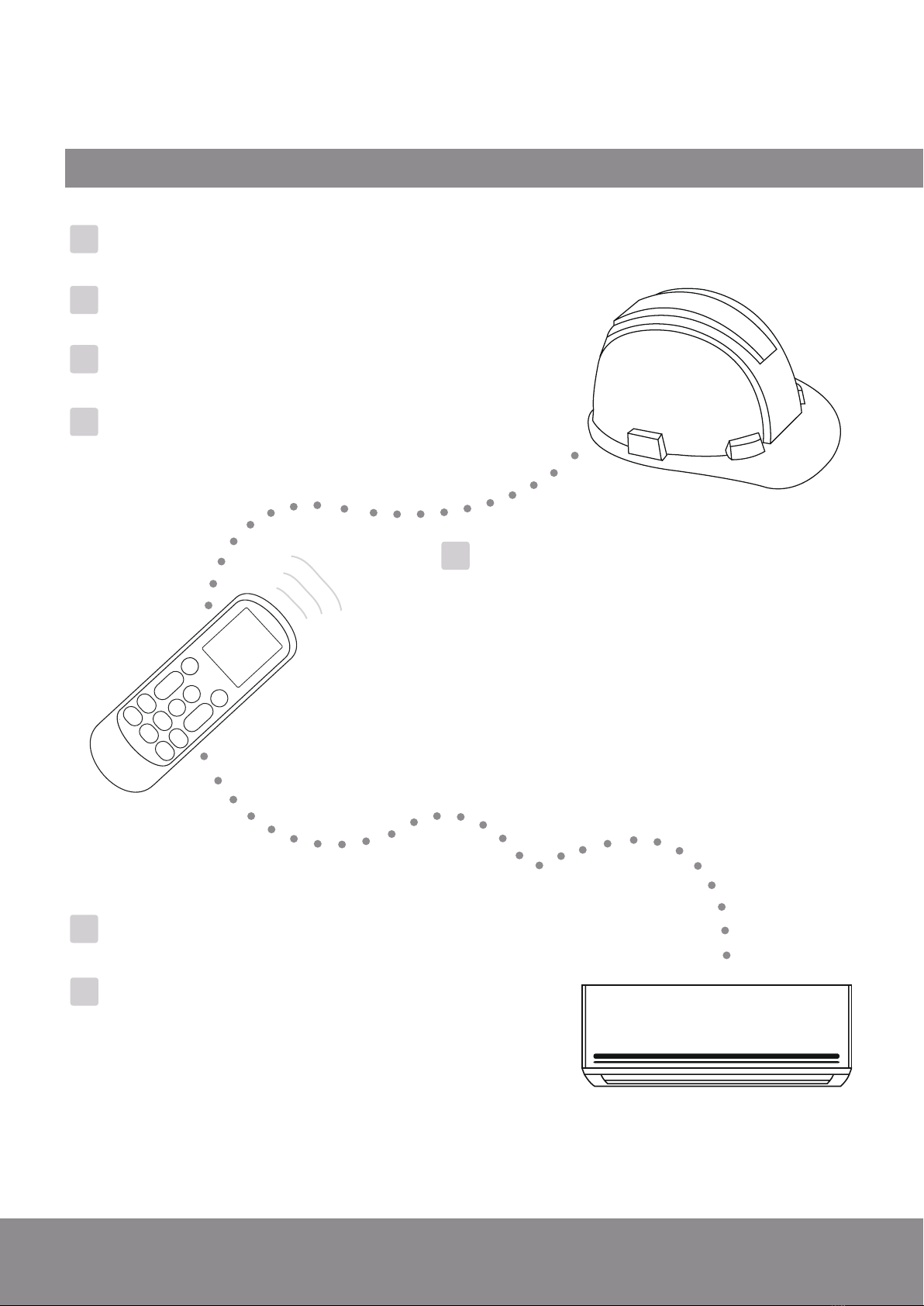
1x Remote Controller
1x Remote Controller Holder
2x Remote Controller Batteries
1x Warranty Card
1x Indoor Unit Mounting Plate
1x Condensate Drain Hose
Name
Appearance
1x Wrapping Tape
1x Wall-Hole Packing Sealant
1x Wall Sleeve
1x Allen Wrench
1x Set of Mounting Plate Screws
1x Plastic Drain Joint Plug
Connecting Pipe Diameters
9000
12000
18000
24000
BTU Capacity Liquid Line
Gas Line
1/4”3/8”
1/2” 1/4”
5/8” 1/4”
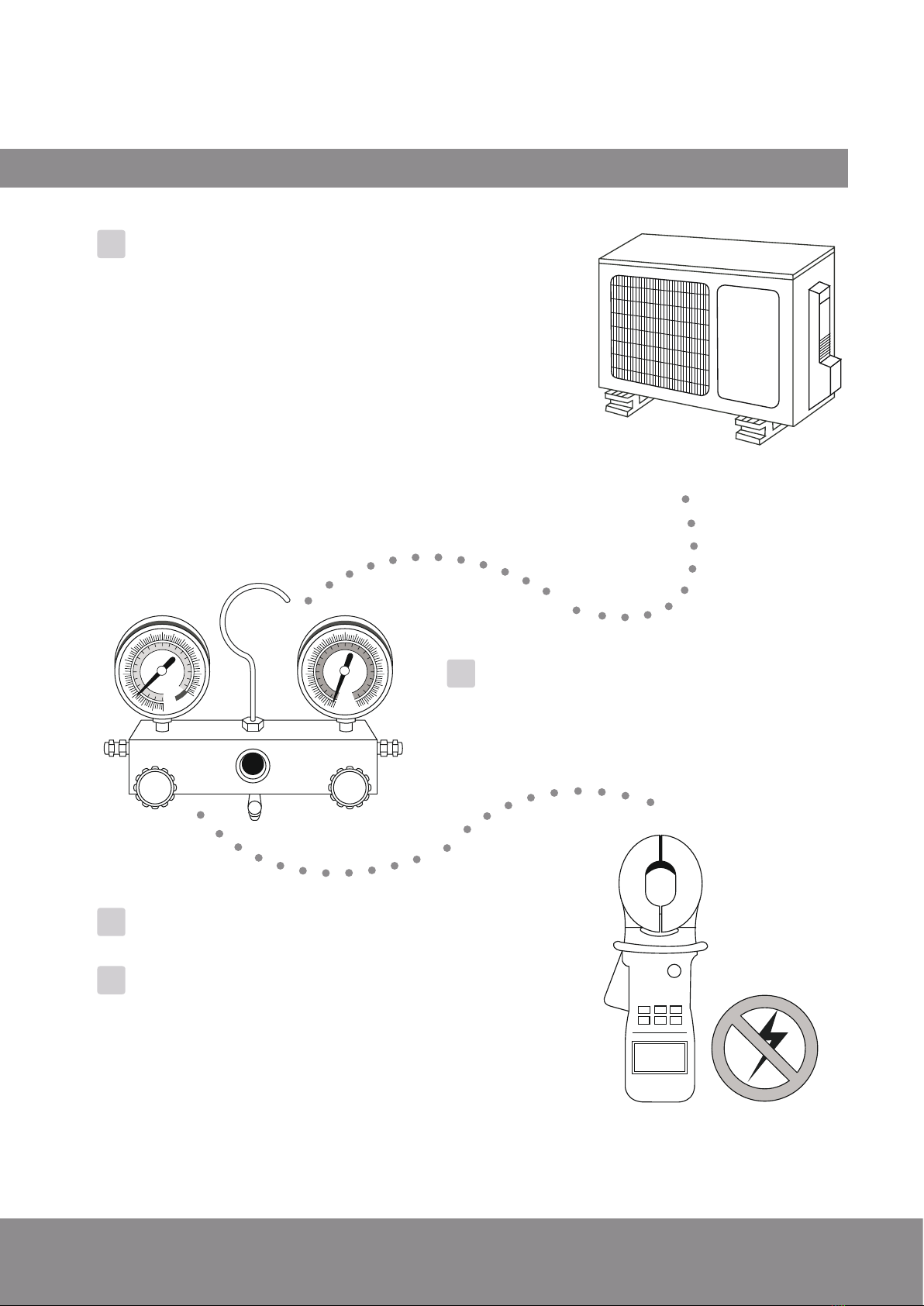
Accessories and Components:
The air conditioning system comes with the following accessories. Use all of the installation
parts and accessories to install the air conditioner. Improper installation may cause the
equipment to fail, or result in water leakage, electrical shock, or fire.
1.Unless this high quality product is registered properly as soon as it is put in service, all referencesmade in this document to the term “warranty” solely refer
tothe Basic Warranty,as further dened below. If this high quality product is registered properly as soon as it is put in service, all references made in
thisdocument to the term“warranty ”refer to the Standard Warranty,also as further dened below.
2.Warrantyis provided by Parker Davis HVAC International, Inc. (hereinafter referredto as PD), the supplier of Pioneer® branded Split System Heat
PumpProducts (hereinafter referred to as Products),covering all parts of the Products, subject to the following details:
a.Typesof I nstallations:Warranty applies to all Products, installed in a residence. Warranty also applies to Productsclassied as light
commercialProducts, installed in commercial properties.
b.Product Registration: Registration is not requiredfor the availability of the Basic Warranty. Warrantyregistration is strongly urged and required
forthe validity of the Standard Warranty.To register the Product, withinone week after the Product is properly installed, ll out the warranty
registrationcard packed with the Product and send it in as instructed in the form OR convenientlyregister online at www.pdhvac.com and use the
registrationlink.
c.Exclusions to WarrantyCoverage: Warranty does not apply to any Product that:
i.Are installed outside the United States of America.
ii.Are operated in unoccupied structures or used for purposes other than comfort cooling / heating.
iii.Are residential Products, but installed or used for commercialpurposes.
iv.Has been removed fromthe place it was originally installed and reinstalled at another place.
d.WarrantyCoverage: The warranty covers the parts of the Products, which may become defective due to the quality of the materials or
workmanship,under normal use and proper maintenance.
e.WarrantyD oes not Cover:PD is not responsible for any warranty claim due to:
i.Damages or repairs arising as a result of a faulty installation or wrong application.
ii.Damages or repairs arising from any external perils, out of PD’scontrol, such as res, storms, accidents, oods, broken or frozen water
pipes,electrical surges, input power with under or overvoltage, lightening or existenceof corrosive substances nearby.
iii.Damages or repairs arising from use of non-compatible parts, alterations, modications or improper applications.
iv.Necessary maintenance required for the properoperation of the equipment, such as cleaning of all air lters, heat exchangers, fans and
blowers,any necessary lubrication of internal components and maintenance of external accessories.
v.Damages or repairs needed because of using parts, supplies or other add-on components that are not supplied by or approvedfor use by
PD.
vi.Damages or repairs as a result of improper use, poor maintenance, wrongoperation or improper service.
vii.Changes that can be considered cosmetic, not aecting the systems performance, including but not limited to small n damages.
viii.Resetting of power or the circuit breakers and replacement of other types of fuses, both internal and external.
ix.Any damages of repairs caused by the use of dirty, recycled, wrong type or unapprovedrefrigerants and lubricants.
x.Damages or repairs due to moisture, air,dust, sand, dirt, etc., that have been allowed into the system by improper handling of system parts
andcomponents during installation.
xi.Damages or repairs caused by continuing use the Product, after a malfunction has been noticed or indicated at the display module,
throughan error code.
xii.Damages or performance issues due to improper matching, Product selection, under-sizing, over-sizing,improper installation or misuse.
f.WarrantyBegin Date: Warranty begins on the date of installation and commissioning of the Product, in existing residences and commercial
buildingsand on the date of sale of the dwelling, for the new residential construction to the rst buyer.However, the warranty beginning date cannot
exceeda date, further than 6 months following the manufacturing date of the Product as coded in the serial number.Warranty is provided only to the
rstoriginal owner of the Product, where it is originally installed, and is not transferableto the subsequent owners.
g.WarrantyEnd Date: Products that have not been registered as instructed above are covered under the Basic Warranty.The Basic Warranty lasts
fora period of up to one year.Products that have been properly registered as instructed above will be covered under Standard Warranty.The
StandardWarrantylasts for a period of up to ve years as further explained below in detail and only as long as the original registered owner, own
andreside in the dwelling, or operate the business in the property,in which the Product had been originally installed.
h.Remaining Warranty: Any part, component or Product that was replacedunder the terms of the warranty will be covered under the same
warrantyand only for the duration in which the original warranty for the Product is applicable,as commenced on its begin date.
i.Warranty Procedure:PD will furnish a new or remanufactured replacement part, without any charge for the part itself, for the replacement of any
partthat has been determined to have failed, by PD at its sole discretion, due to defects in its materials or workmanship under standard use and
propermaintenance. Associated shipping costs forthe replacement parts may also be covered at PD’s expense, at its own discretion and under
certainconditions, while the shipping method used will be solely determined by PD. Otherwise, the payment of the shipping costs for the part will be
thesole responsibility of the owner of the Product. PD reserves the right to ask the owner of the Product to return thefailed par t to PD,before
orafter a replacement part may be sent out.
j.Labor cost, materials and other costs: Any labor costs and/or the costs for the supplies or materialsused or purchased in the eld for the
replacementof the defective part, remain the responsibility of the owner.No other costs, involved in diagnosis, lodging, transportation, servicing, repair,
replacement,installation, removal, shipping,etc., are to be covered under the warranty.
k.Refrigerant: Any costs related to charging, recharging,adjustment, or removal of the refrigerant, and the cost of the refrigerant itself, are not
coveredunder any circumstances.All Products go through vigorous quality controls at various stations and leave the factory in perfect working
andsealed condition. Products are individually tested in highly sensitive helium vacuum chambers forexistence of refrigerant leaks. Therefore PD
doesnot cover any claims related to the lack of refrigerantin new Products, discovered upon arrival, or during installation, as well as subsequent
refrigerantlosses occurring at any time afterward
LIMITED PARTS WARRANTY
Pioneer® Brand Split System Heat Pump Products
© 2022, PARKER DAVIS HVAC INTERNATIONAL INC.