Simple Pump 100 User manual

page 1 © Simple Pump Company
INSTALLATION INSTRUCTIONS FOR THE SIMPLE PUMP
SOLAR-POWERED MOTORIZED PACKAGE
(SOLAR MOTOR OPTION)
LAST UPDATED: June 22, 2022
(The following instructions are very detailed, and should tell you everything you
need to know. If you have questions, please phone 877-492-8711, ext. 6)
SIMPLE PUMP COMPANY
2516 Business Parkway, Unit B / Minden, NV 89423
Phone: 877-492-8711 (toll free)
Mon-Fri: 8am-5pm PST (GMT/UTC -8hours)
Fax: 888.826.1444 (toll-free)

page 2 © Simple Pump Company
TABLE OF CONTENTS
INTRODUCTION....................................................................................................................... 2
SPECIFICATIONS ..................................................................................................................... 3
RECOMMENDED OPERATING ENVIRONMENT AND APPLICATIONS .................................................. 3
SECTION 1: UNPACKING AND TOOLS REQUIRED ......................................................................... 6
SECTION 2: POWER SOURCE AND CONTROL BOX INSTALLATION AND STORAGE ............................ 7
SECTION 3: SOLAR PANELS AND MOUNT.................................................................................... 8
SECTION 4: LBLD ASSEMBLY PREPARATION................................................................................ 9
SECTION 5: PREPARING YOUR EXISTING PUMP ........................................................................... 9
SECTION 6: INSTALLATION......................................................................................................11
SECTION 7: ALIGNMENT..........................................................................................................14
SECTION 8: ELECTRICAL CONNECTIONS ...................................................................................15
SECTION 9: OPERATION ..........................................................................................................18
SECTION 10: INSTALLING A FLOAT OR PRESSURE SWITCH .........................................................20
SECTION 11: TROUBLE-SHOOTING ...........................................................................................21
SECTION 12: MAINTENANCE ....................................................................................................22
SECTION 13: WARRANTY.........................................................................................................22
INTRODUCTION
Thank you for purchasing a Simple Pump gear motor assembly. This Weather Resistant Motorized Pump
with Linear Bearing Link Drive (LBLDWR) is designed for use with the Simple Pump model 100, 125, and
200 hand pumps. When installed on the Model 100, it delivers up to 1.0 GPM from a totally dynamic
head (TDH) of 225 feet. See detailed limits below. When installed on the Model 125, the gear motor is
capable of delivering up to 2.0 gallons of water per minute (GPM) from a total dynamic head (TDH) of
150 feet. When installed on the Model 200, it delivers up to 4.5 GPM from a totally dynamic head (TDH)
of 60 feet.
The linear bearing link drive translates the rotary action of the 24 VDC gear motor to move the pump
rod up and down on a precision ground and polished stainless shaft guided by two linear TEFLON bearing
carriers.
The Motorized System weighs about thirty (30) pounds, so depending on your level of strength, you
may want to perform this installation with a helper.

page 3 © Simple Pump Company
SPECIFICATIONS
Motor Rating
.151 HP continuous
Gear Ratio
30:1 @ 91.0% efficiency
Output Torque
195 in/lbs. continuous
Output Torque Maximum
400 in/lbs. @45.9RPM @ 16.63 amps
Nominal Output RPM
60.1
Efficiency
64.24%
Full Load Motor Current
7.32 amps
Allowable Voltage Range
Typical temperature of casing, operating
24 to 30 VDC
in 72˚F ambient
110˚ Fahrenheit
RECOMMENDED OPERATING ENVIRONMENT AND APPLICATIONS
AMBIENT TEMPERATURE
DC motors operating in ambient temperatures above 100˚F lose operating efficiency -- the hotter the
ambient temperature, the less efficient. If the temperature at the planned site regularly peaks above
100˚F, we recommend operation of the motor in shade. The component box needs to be mounted near
the batteries and out of the sun in a protected environment as it contains electrical equipment.
CONSISTENT SOURCE OF DC POWER
As with any DC motor, precaution must be taken to prevent operation under low voltage conditions --
below 23.5V with the 24VDC model. The provided charge controller already has Low Voltage Disconnect
(LVD) capabilities built in. See the instruction manual provided for details.
RECOMMENDED PUMPING CONFIGURATION
The solar-powered Simple Pump is an integrated, standardized system that will provide water within a
specified head limit. This head limit is based on the pumping cylinder that is used. Please see the table
below for the different head limits. The Total Dynamic Head (TDH) is a combination of up to three
factors, not all factors apply to every installation.
1. The lift from the static water level. (Example - 85’)
2. Any vertical distance from the well head. (Example –15’)
3. Any pressure that is being pumped (1 PSI = 2.31’, 45PSI ≈ 100’)

page 4 © Simple Pump Company
When calculating your TDH, evaluate your specific application and determine how many of the three
you need to account for in your application.
See example below. The well has a 78’ static water level, the water is being lifted an additional 16’
above ground level, and is being pumped into a pressure tank. This particular application would require
the 100CA.
Static Water Level –78’
Additional Vertical Lift –16’
Pressure –100’ (45 PSI)
Total Dynamic Head (TDH) –194’
Cylinder Assembly
24VDC TDH Limit
100CA
225’
125CA-82515
150’
200CA
60’
Please evaluate your application to ensure that it fits within the limits of the system. If your desired
application exceeds the limits of our system, there are alternative ways to meet your goals. The best
way to reduce the TDH on our system is to find an alternative way to pump into pressure. Using an
ambient (i.e. non-pressurized) storage tank along with a small DC powered transfer pump will allow you
to pump the water into your pressure tank. The Simple Pump would be used to bring water to the
surface and fill the ambient tank. The transfer pump would pump the water from the ambient storage
tank into the pressurized system.
Since needs for tank volume and pumping capacity will vary greatly, we do not provide the ambient
tank or transfer motor.
Tanks: See the range of Bushman drinking water storage tanks, on the bottom of this page:
http://www.loomistank.com/bushman-tanks.shtml
Transfer pump: Pumps designed specifically for this job are available from a number of vendors, e.g.
Dankoff, Surflo and Jabsco. Price range depends on the manufacturer and model, anywhere from $150-
$1000.

page 5 © Simple Pump Company
This configuration raises the overall reliability and longevity of the system. Transfer pumps include an
integrated pressure switch. The switch turns the transfer pump on and off, according to a target
pressure. If you are able to use the Simple Pump to pump into pressure, we STRONGLY suggest that you
wire in a pressure switch to control the ON/OFF state of the system (See Section 10 for details). If the
pump is not controlled in this way and is left on, it could exceed the allowed pressure and potentially
damage both the pressure tank and/or the Simple Pump gear motor. If you have any questions or
concerns about your application and the limits explained above, please call us at 877-492-8711,
extension 6.
UNSUPPORTED APPLICATIONS
Operating the Motorized System (LBLDWR Option) in certain configurations voids its warranty.
‣Exceeding the rated total dynamic head limit of the Motorized System.
‣Not performing normal maintenance events
SOLAR POWER SOURCE
Choose a location as close to the well as possible and practical, this helps eliminate any voltage drop
between components (i.e loss of available power). Keep in mind the cables provided for the connection
from the solar panels to the control box are 25’ in length. (Custom lengths are also available, however
the gauge of the wire may need to increase depending on the length required.)
Also keep in mind that the solar panels will need to be facing south and should be positioned such that
they are not shaded by any other structures, plants, trees, or even the pump itself.
Batteries
You will need two 12v batteries, Group 27 or 31 Deep Cycle (from almost any auto parts store) and
minimum 100 amp-hour rating.
Lead acid will be the least expensive, probably around $125.00 each on sale. AGM will be about three
times what the lead acid cost but will provide longer run time.
Battery storage is left to you to determine, following is guidance on what to think about when picking
an enclosure. The batteries need to be kept clean and dry at all times, out of the rain, snow, ice, and
direct sunlight, to increase longevity. The battery enclosure should be high enough off the ground or
sealed to avoid rain runoff and snow accumulation (if applicable). This system requires that you place
the batteries as close to the well head as possible in an enclosure meeting the description above. The
cables provided to connect the batteries to the control box are 4’ in length. The cables provided to
connect from the control box to the drive system are 12’ in length. We recommend that both the
batteries and the control box are stored in the same enclosure/building/location.

page 6 © Simple Pump Company
PROFESSIONAL HELP?
If this is more complex than you planned, there are alternatives.
Anyone with NABCEP (North American Board of Energy Practitioners) certification, and experience
configuring off-grid systems, is almost certainly qualified to help. However, while all NABCEP-certified
professionals must learn about off-grid systems, most pursue grid-tie solar systems -- a very different
field. This is why it is important to ask about recent experience.
SECTION 1: UNPACKING AND TOOLS REQUIRED
Carefully unpack all items from all boxes and the crate (if panels and mounting hardware purchased).
CONTENTS OF CRATE
(2) Solar Panels
(1) Pole Mount Kit
(1) 4” x 9’ Galvanized Pole w/ threads on one end
(1) 4” x 3.5’ Galvanized Pole w/ threads on one end
(1) 4” Galvanized coupling
CONTENTS OF BOXES
(1) 24VDC LBLD Assembly, with aluminum gear motor cover and linkage cover
(1) 15” x 15” Control Box (charge controller, timer, solenoid, fuse blocks, and terminal block)
(2) Control box mounting brackets w/ bolts
(4) 10-32x3/8” Stainless bolts for control box mounting brackets
(2) 25’ solar cables (white/black w/ MC4 connectors
(2) 12’ load cables (red/black) w/ MC4 connectors
(2) 4’ battery cables (red/black) w/ MC4 and loose ring connectors
(1) 2’ battery jumper w/ ring connectors
(1) 3/4” x 13" stainless steel pump rod extension
(4) 1/4-20 x 3/4" SS SHCS fasteners for mounting the LBLD to the pump head
(4) 15A (24V) ATO/ATC prong style fuses (spares)
(1) MM/F MC4 Branch Connector
(1) FF/M MC4 Branch Connector

page 7 © Simple Pump Company
TOOLS REQUIRED
(4) Allen wrenches: 9/64", 3/16", 5/16"
(2) Channel lock pliers
(1) Level
(1) Medium Phillips screwdriver
SECTION 2: POWER SOURCE AND CONTROL BOX INSTALLATION AND STORAGE
POWER SOURCE RECOMMENDATIONS
The power source for these motorized systems are deep cycle batteries. The system is not designed to
run panel direct, meaning that you cannot directly connect the output of the panels to our motorized
system. The provided charge controller will manage the charging of the batteries. The charge controller
has a built in Low Voltage Disconnect (LVD) to manage when the batteries drain below the required
voltage.
LOCATION AND STORAGE
To avoid increased voltage drop we recommend that the power source and control box be located as
close to the well head as possible. We provide two sets of cables with this system. The cables to
connect the batteries to the control box are 4’ long, so you will need to make sure the control box is
within close proximity to the batteries. The cables to connect the control box to the motorized system
are 12’ long, so the location of the batteries and control box need to be within this proximity to the
motorized system/well head.
Both the batteries and the control box will need to be in protected storage. Storage should protect the
power source and control box from the elements including, rain, snow, and direct sunlight. NOTE: The
control box is mildly weather resistant, but definitely not weather proof.
BATTERY CONNECTIONS
Once the 12V batteries are placed in their final location it is time to make the series connection. This
will take them from being two 12V batteries to one 24V bank. You will want to get the positive terminal
from one battery close to the negative terminal on the other battery. We have provided a 2’ piece of
black 10ga cable, plus two ring connectors. Cut the cable to the correct length and crimp on the ring
connectors. Using the jumper provided connect the positive terminal on the first battery to the negative
terminal on the second battery. At this point the negative terminal on the first battery and the positive
terminal on the second battery are not being used, we will connect them to the control box later.

page 8 © Simple Pump Company
SECTION 3: SOLAR PANELS AND MOUNT
Photo is the example of the mounting hardware we provide standard. If you have purchased
your own pole or roof mount hardware it should have its own assembly instructions. The instructions
for our standard pole mount system will be provided inside of its box.
GENERAL TIPS FOR INSTALLING THE POLE-MOUNT SYSTEM
‣We suggest you set the pole as the first step. The concrete will require a couple days to dry, so this
will give you time to install the pump and or drive system in between.
‣Make your hole at least 3 feet deep and 10 inches in diameter, with post hole digger or by hand.
‣Determine if you need to use the 3.5’ pole extension and coupling. If this is required due to the
desired height of the panels, you will want to either weld the pole to the coupling once threaded, or
drill through and put a large bolt through. This will keep it from turning in heavy winds.
‣Place the pole in the hole, check the pole is vertical using a level, and brace to stabilize position.
‣We suggest three (3), fifty (50) pound bags of fence post concrete.
‣Allow concrete 2 days to dry before mounting the panels.
‣Follow the instructions provided with the pole mount system to complete the installation of the
provided solar panels.
‣Run the conduit and cables (white/black) provided for connecting the solar panels to the control box.
DO NOT connect the cables to the solar panels or the control box at this point.
‣Make sure all cabling is run cleanly using conduit and zip ties where needed.
NOTE ON GROUNDING
The modules are grounded in the J-box by means of a green bonding wire that attaches to the aluminum
frame, which is then bolted to the aluminum bracket, that is bolted to the steel pipe, which is sunk in

page 9 © Simple Pump Company
the ground. Everything else in the system is in an, “above ground”, configuration, i.e. not a chassis
ground. If the batteries fail or melt down the MorningStar will isolate them from the system with its
built-in circuit protections. (If the system takes a direct lightning strike nothing will save it.)
SECTION 4: LBLD ASSEMBLY PREPARATION
Using the 9/64" Allen wrench, remove the six screws that attach the linkage cover. Set it to the side,
it will be installed later. Cut the zip tie that is securing the clevis, this was for shipping purposes only.
SECTION 5: PREPARING YOUR EXISTING PUMP
Your Simple Pump Hand Pump should already be installed and pumping water without any binding and
with an overall smooth operation prior to attempting to install this gear motor.
You should confirm that your pump is delivering at least one gallon of water with approximately 25
strokes with the lever handle system (model 100). If you have the model 125, your pump should be
delivering about one gallon of water in approximately 15 complete strokes. If you have the model 200,
your pump should be delivering about one gallon of water in approximately 6 strokes.
Starting with a fully-functional lever-arm pump, what follows are the step-by-step installation
instructions.
REMOVE THE LEVER ARM MECHANISM
Using the 3/16" Allen wrench, remove each of
the four fasteners holding the lever arm
mechanism to the pump head.
Remove the lever arm bracket and lever (they should
still be connected) from the 3/4" stainless rod. These are
reverse threads, the direction you screw is the opposite
of normal -- turn clockwise to remove, rather than the
normal counterclockwise.
page 10 © Simple Pump Company
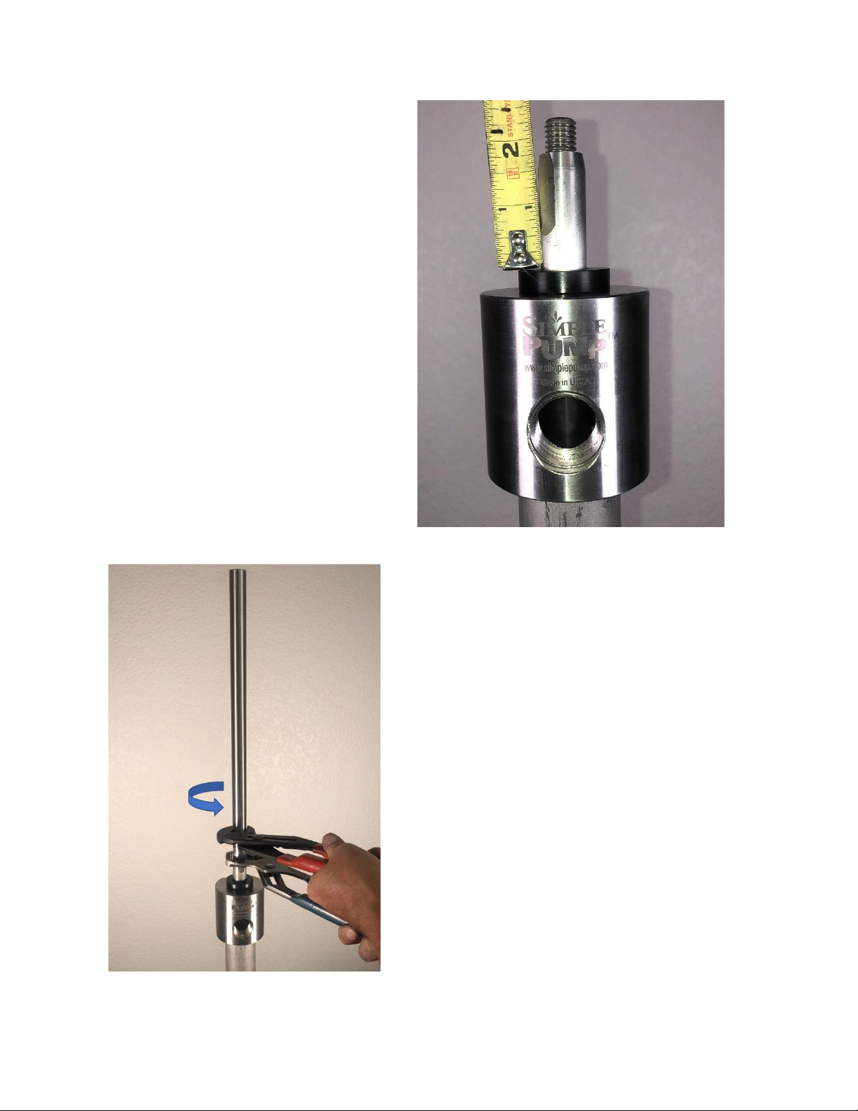
Before adding the 13” Rod Extension you will
need to verify the height of the existing Pump
Rod. With the Pump Rod at the bottom position
measure from the Rod Gland to the base of the
threads on the Pump Rod. The Pump Rod will
need to sit somewhere between level with the
Rod Gland and less than 3.0” above it.
If the measurement is above 3.0”, it means that
the lift rod protrusion above the top drop pipe
was above the 4”-6” range specified in the hand
pump installation instructions. In the event this
needs to be fixed, please reference the hand
pump installation instructions for details on how
to make the adjustment.
Add the 13” Rod Extension to the top of the existing pump
rod. As mentioned above, these are reverse threads so
you will go counterclockwise to tighten. Use the two
channel locks to tighten.
NOTE: When using the Motorized System, like with the
Hand Pump, half of the Riser Tube must be below the well
cap. This means that when using the PHA2 only 12” of
Riser Tube can be showing above the well cap, when using
the PHA47, only 24” can be showing.

page 11 © Simple Pump Company
SECTION 6: INSTALLATION
NOTE: The Motorized System weighs about thirty (30) pounds.
We suggest that this portion of the installation be done with a
helper.
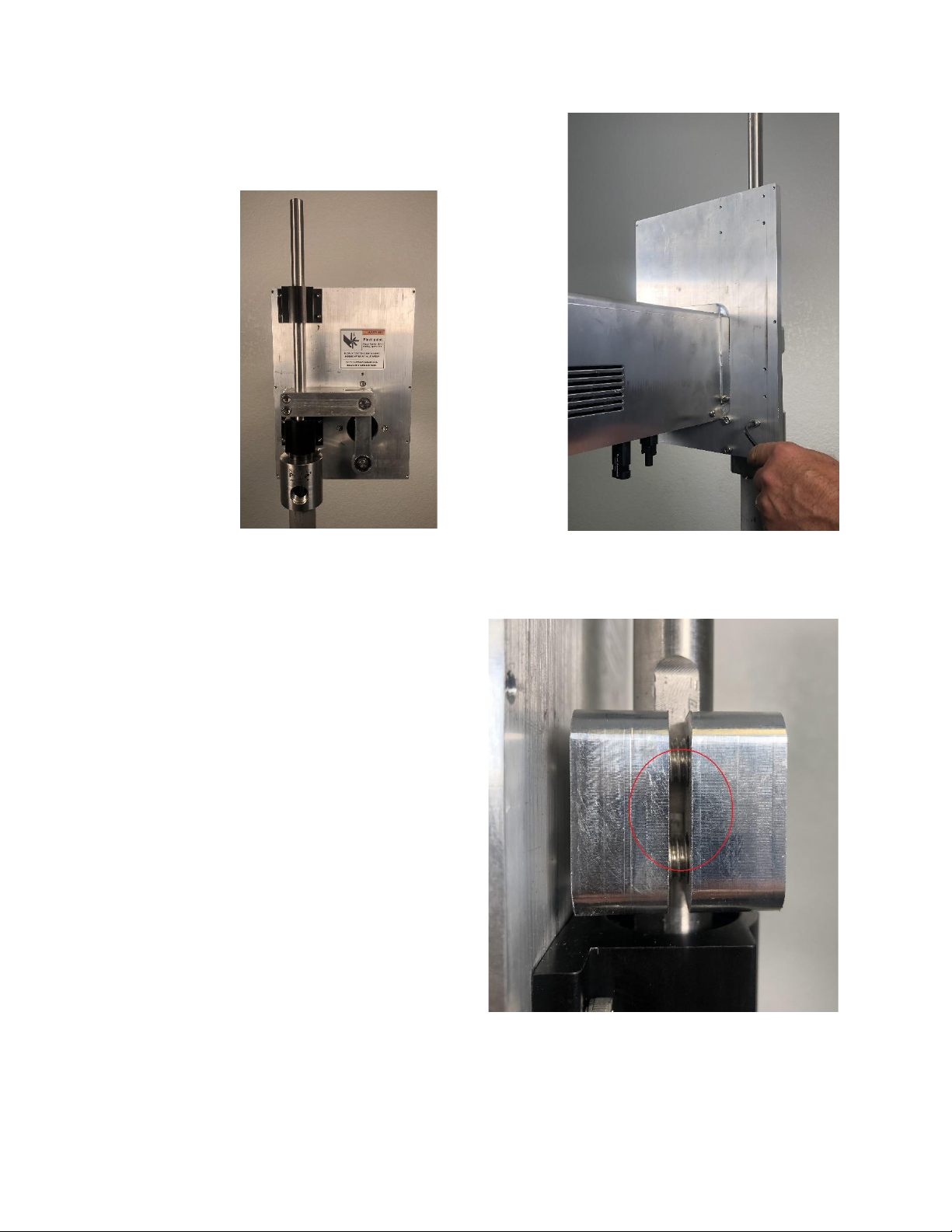
Make sure the orientation of the unit is correct before taking the
next step. The cabinet portion of the unit faces away from the
pump head. The bottom of the unit is where the two MC4 style
plugs are mounted.
The clevis will need to be in the bottom position for the
installation as shown in the image to the right, circled in red.
Lower the assembly onto the pump head so that the pump rod and
extension are inserted through three (3) openings. As the unit is lowered
down, the rods move through the below pieces, in order.
•The lower linear bearing
•The clevis
•The top linear bearing
The tolerances are tight between the clevis ID and the shaft OD. You may
need to wiggle the yoke while lowering the unit to get it to drop all the
way down.
There is a 1/4" of space between the bearing housing and the top of the
rod gland when the holes are fully aligned. The rod gland is the topmost
exposed component on the pump head.
page 12 © Simple Pump Company
Screw the four 1/4-20x3/4" SS SHCS mounting bolts through
the holes just aligned, fastening the mounting plate to the
pump head.
This next step is very important. We will need to
make sure the piston is in the correct position. To
do this, grab the portion of the 13” rod extension
that is sticking out of the top of the unit and pull up.
The ideal location for the joint between the standard
pump rod and the 13” extension is in the middle of
the clevis, as shown in the photo to the right, circled
in red. If your rod to pipe ratio is correct, you
should need to lift the rod up to get it into the
position explained above.
It may be necessary to wiggle the clevis in order to
move the rod upward. With deeper static water
levels, it could take a fair amount of force to lift the
rod.
page 13 © Simple Pump Company
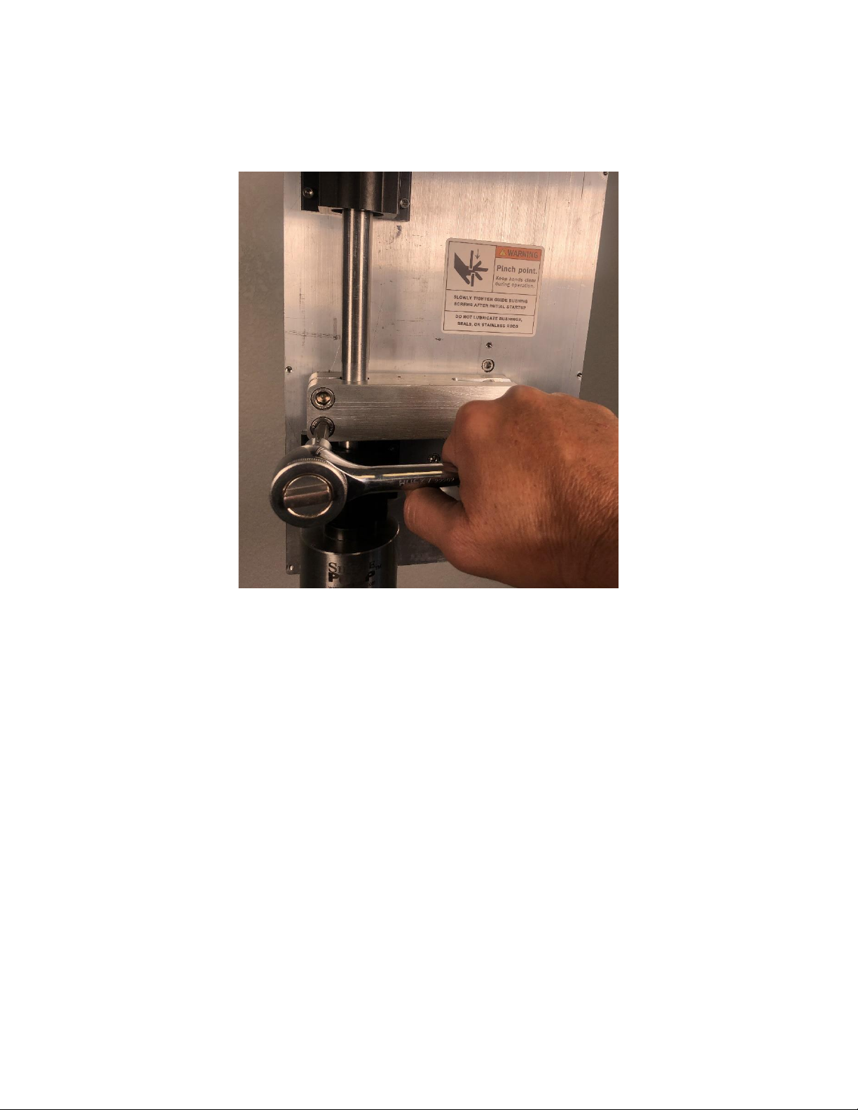
Then, using a 5/16" Allen wrench, tighten the two stainless steel socket head cap screws on the clevis.
This pinches the clevis to the stainless rod. These need to be very tight. You will notice when you
tighten one and move to the other it will appear loose. Keep tightening in sequence until both are tight.
page 14 © Simple Pump Company
SECTION 7: ALIGNMENT
The next step is to check/adjust the alignment of the pump rod with the linear bearings and the mounting
plate. Completing this alignment will prevent any binding between the linear bearings and the pump
rod.
Make sure all eight (8) 8-32x1/2 SS socket head cap screws that hold the top and bottom linear bearings
to the mounting plate are loose. We won’t tighten these fully until the alignment process is complete.
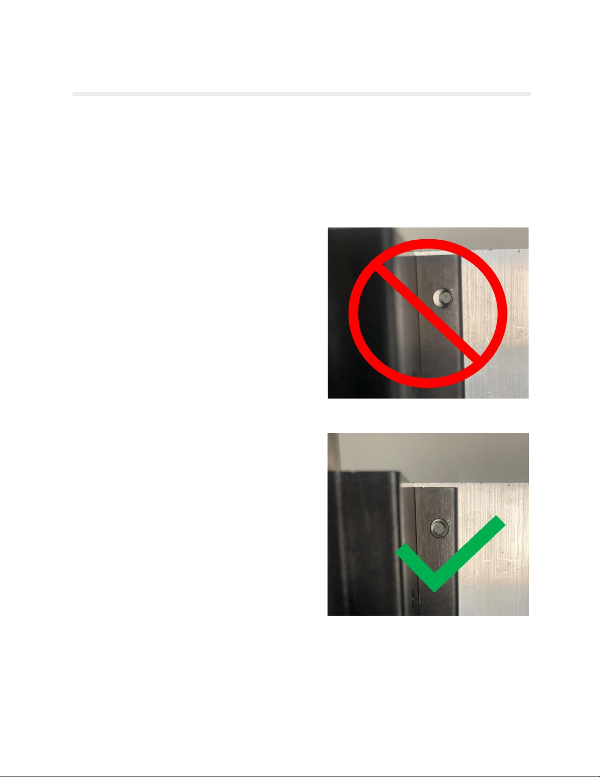
Remove the four (4) 8-32x1/2 SS socket head cap
screws that are holding the top linear bearing in place.
This step ONLY needs to be performed on the TOP linear
bearing. Once removed compare the placement of the
holes in the linear bearing with the holes threaded into
the mounting plate. See image.
If these holes do not line up, it will likely be that the
holes in the mounting plate are to the right of the holes
in the linear bearing, as shown in the picture to the right.
You want them to be lined up like the image to the
bottom right with the green check mark.
The adjustment for this requires that you loosen the four
(4) ¼-20x3/4 SS cap screws holding the unit to the
pump head. Lift up on the bottom right corner of the
mounting plate slightly and tighten the four mounting
bolts. Check the alignment between the holes in the top
linear bearing and the mounting plate again. Make as
many adjustments as necessary to get the holes lined
up like the image to the right.
Once alignment is verified make sure the ¼-20x3/4 SS
cap screws holding the assembly to the pump head are
fully tight. You can now put the four (4) 8-32x1/2 SS
cap screws back into the top linear bearing. At this point
just make these screws finger tight.
We will do final alignment adjustments in Section 7 below.

page 15 © Simple Pump Company
SECTION 8: ELECTRICAL CONNECTIONS
There are three different sets of cables provided with this system; PV (solar), battery and load.
CAUTION: MAKE SURE THAT THE ON/OFF SWITCH IS IN THE OFF POSITION WHEN MAKING ALL
ELECTRICAL CONNECTIONS. THE SWITCH IS OFF WHEN THE BOTTOM IS DEPRESSED AND ON WHEN
THE TOP IS DEPRESSED. THERE ARE PINCH POINTS IN THIS SYSTEM. EVEN IF YOU ARE CERTAIN THE
SWITCH IS IN THE OFF POSITION, MAKE SURE THAT ALL PINCH POINTS ARE CLEAR.
PV (SOLAR)
This will create a connection between the control box and the solar panels. If using our standard system,
you have been provided with two branch connectors to put the panels in parallel. Using the branch
connectors connect the positive leads from each panel together and the negative leads from each panel
together.
Positive Branch Connector Negative Branch Connector
You can now connect the PV cables to the branch connectors. Connect the white (+) cable to the positive
branch connector. Connect the black (-) cable to the negative branch connector.
You can now connect the PV cables to the control box. The white (PV+) cable needs to be plugged into
the left most MC4 connector on the control box. The black (PV-) cable needs to be plugged into the
second from the left most MC4 connector on the control box. See image below. The control box is
marked with PV+ and PV- just in front of the connector for more guidance.

page 16 © Simple Pump Company
BATTERY
This will create a connection between the control box and the batteries. To reduce voltage drop you will
want to place the batteries as close to the control box as possible. We have provided a set of 4’ long
cables with MC4 connectors on one end and loose ring connectors for the other end. With the control
box mounted and the batteries in their set position, measure the distance between the two and cut to
size. Crimp the ring connectors to the cables.
You can now connect the Battery cables to the battery. Connect the red (BAT+) cable using the ring
connector to the remaining positive terminal on the one battery. Connect the black (BAT-) cable using
the ring connector to the remaining negative terminal on the other battery.
You can now connect the Battery cables to the control box. The red (BAT+) cable needs to be plugged
into the third from the left MC4 connector. The black (BAT-) cable needs to be plugged into the fourth
from the left MC4 connector. See image below. The control box is marked with BAT+ and BAT- just in
front of the connector for more guidance.

page 17 © Simple Pump Company
LOAD
This will create a connection between the control box and the LBLD drive unit. Make sure the switch on
the control box is in the off position. The off position is when the bottom of the switch is depressed in.
Even if the switch is in the off position, make sure all pinch points are clear.
We have provided the two (2) 12’ cables for this connection. These cables already have MC4 connectors
on both sides so do not cut or change their length. Use the red (LOAD+) cable to connect the two
positive MC4 connectors between the control box and the drive unit. The LOAD+ connector on the
control box is the second from the right. Use the black (LOAD-) cable to connect the two negative MC4
connectors between the control box and the drive unit. The LOAD- connector on the control box is on
the far right. See image below. The control box is marked with LOAD+ and LOAD- just in front of the
connector for more guidance.
The LBLD should now be fully powered!!!

page 18 © Simple Pump Company
SECTION 9: OPERATION
Now that the initial alignment is complete and the power has been connected, we can perform the initial
startup. During the initial startup we will verify the alignment and tighten the linear bearings for the
break in period.
NOTE: During the first startup and break-in period, leave the pump
outlet open or pump through a short drinking-water quality garden
hose unrestricted. We recommend a break-in period of 6 hours.
Make sure your power source can provide adequate power for the
break-in period.
CAUTION: The first startup will be done without the cover installed.
This will expose pinch points so use extreme caution.
Turn the switch to the ON position. The unit should start to run. Let
it run until you start to produce water. Once it is producing water
you will need to tighten the screws on the linear bearings. We do
this while the unit is running as it will center the linear bearing to a
natural, non-binding position. BEWARE OF THE PINCH POINTS FOR
THIS NEXT STEP. While the unit is running, tighten the top linear
bearing first, only tighten the top two screws to avoid pinch points.
Next, tighten the lower linear bearing, only tighten the bottom two
screws to avoid pinch points.
Let the system run for about 5 minutes then turn it OFF and follow the two steps listed below.
1. DO NOT DO THIS STEP WITH THE SYSTEM RUNNING. Check the temperature of the pump rod that
is sticking out above the unit. If it is ambient or a little warmer than ambient move to step two. If
it is really hot there is a binding issue and you need to go back to the alignment step and re-verify.
If you have verified and it continues to get really hot, please contact our technical support.
2. Tighten the remaining loose screws on both the top and bottom linear bearings, there should be
four (4) left to tighten.

page 19 © Simple Pump Company
Attach the cover to the LBLD mechanism. Use your 9/64”
Allen Wrench for the six (6) 8-32 SS SHCS that attached
the cover to the mechanism’s mounting plate.
Start the system again and begin the 6-hour break-in
period. During the break-in period, leave the pump outlet
open or pump through a drinking-water quality garden
hose unrestricted.

page 20 © Simple Pump Company
SECTION 10: INSTALLING A FLOAT OR PRESSURE SWITCH
If you are planning to utilize a float or a pressure switch, please follow the instructions below. Make
sure to verify if pumping into pressure will work with your well specifications, you can find details in the
RECOMMENDED PUMPING CONFIGURATION section on page 3.
With any float or pressure switch there should be a supply and return wire. This means there will be two
wires. We have made it very easy to integrate these into our system. Inside the control box you will
see a terminal block. There is currently a jumper on the bottom two most right terminals of the terminal
block. Simply remove the jumper from the terminal block and add the supply wire to the left terminal
and the return wire to the right terminal. See image below. The switch is now integrated.
If you are planning to integrate a pressure switch
you can use a standard pressure switch. When
using DC voltage, you can simply jumper the two
middle terminals and add your supply wire to
one of the outer terminals and the return wire to
the other outer terminal.
Always consider the distance from the pressure
switch to the control box when selecting the
gauge of the wire you are going to use. A
general rule of thumb can be found below.
1’ –10’
16 gauge
11’-25’
14 gauge
26’-75’
12 gauge
> 75’
Utilize Voltage Drop
Calculator found online
Other manuals for 100
2
This manual suits for next models
2
Table of contents
Other Simple Pump Water Pump manuals


Popular Water Pump manuals by other brands

Zoeller
Zoeller N153 owner's manual

Danfoss
Danfoss APP 21-43 Disassembling and assembling instructions

Sherwood
Sherwood G1811-01 Technical guide

Hartell Pumps
Hartell Pumps PlenumPlus KL-1DG-115 IOM manual

Wayne
Wayne PC1 Series Operating instructions and parts manual

Parkside
Parkside PDSS A1 Operation and safety notes


