simplebus Bravo Series Instruction Manual

GROUP S.P.A.
Videocitofono serie Bravo - cablaggio Simplebus
Bravo series video entry phone - Simplebus cabling
Visiophone série Bravo - câblage Simplebus
09 -2005
FT SB2 06
1
2
3
4
5
6
TECHNICAL
SHEET
FOGLIO
TECNICO FEUILLE
TECHNIQUE
GBIF

GROUP S.P.A.
FT SB2 06 2
10
1
2
3
4
5
6
4
14
3
2
1
5
6
7
8
13
12
+
--
15
9
11
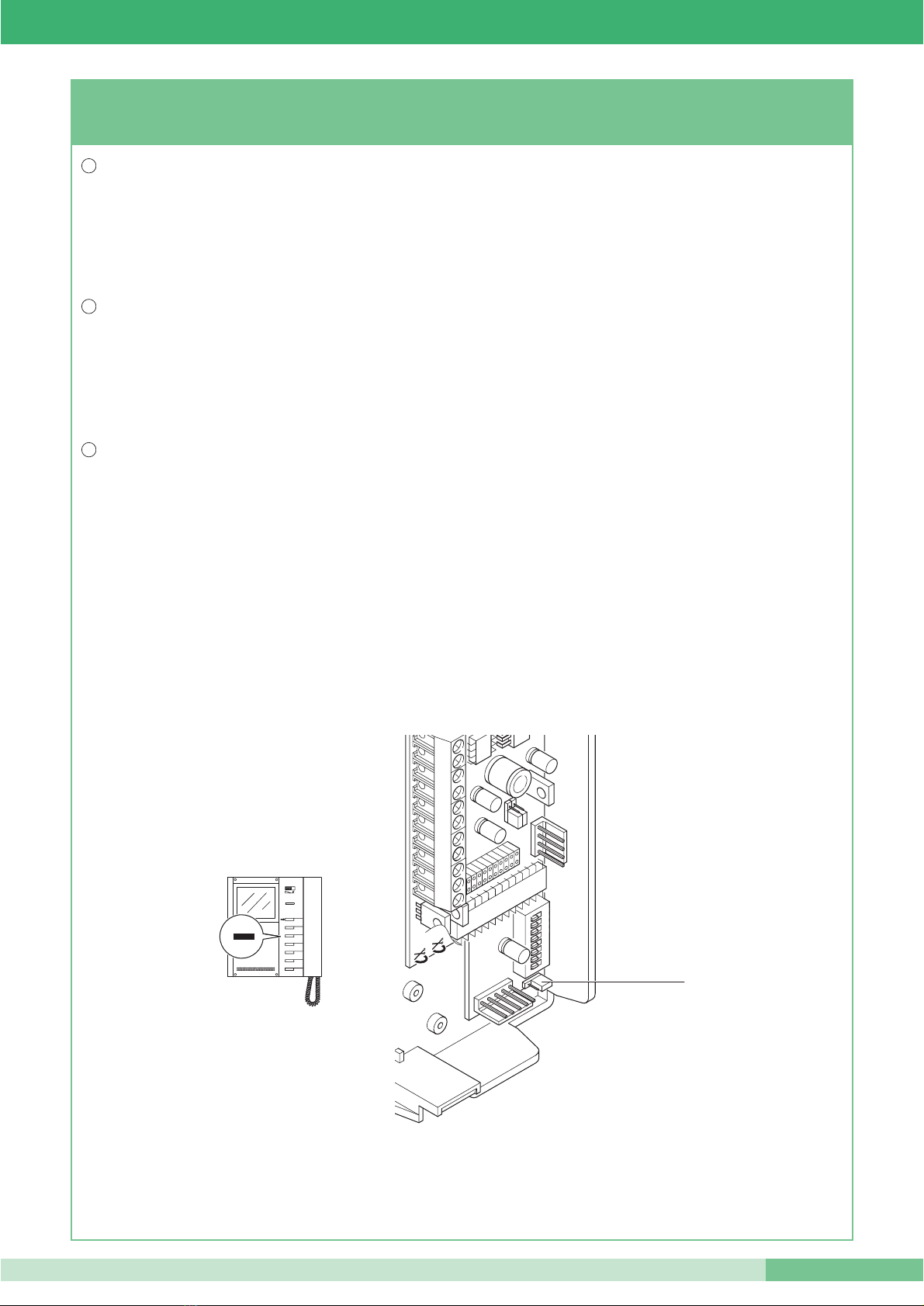
Descrizione monitor e informazioni utente.
Description of the monitor and user information.
Description des moniteurs et informations utilisateur.
I
GB
F
Avvertenze:
• Effettuare l’installazione seguendo scrupolosamente le istruzioni fornite dal costruttore ed in conformità alle norme vigenti.
•Tutti gli apparecchi devono essere destinati esclusivamente all’uso per cui sono stati concepiti. Comelit Group S.p.A. declina ogni responsabilità per un
utilizzo improprio degli apparecchi, per modifiche effettuate da altri a qualunque titolo e scopo, per l’uso di accessori e materiali non originali.
•Tutti i prodotti sono conformi alle prescrizioni delle direttive CEE 73/23-89/336 e ciò è attestato dalla presenza della marcatura CE sugli stessi.
•Evitare di porre i fili di montante in prossimità di cavi di alimentazione (230/400V).
Instructions:
•Install the equipment by carefully following the instructions given by the manufacturer and in compliance with the legislation in force.
•All the equipment must only be used for the purpose it was built for. Comelit Group S.p.A. declines any responsibility for improper use of the apparatus,
for modifications made by others under any title or scope, and for the use of accessories and materials which are not the original ones.
• All the products comply with the requirements of the EEC 73/23-89/336 directives. This is proved by the CE mark on the products.
• Do not run the riser wires in proximity of the power supply cables (230/400V).
Instructions
•Effectuer l’installation en suivant scrupuleusement les instructions fournies par le constructeur et conformément aux normes en vigueur.
• Tous les appareils doivent être strictement destinés à l’emploi pour lequel ils ont été conçus. Comelit Group S.p.A. décline toute responsabilité en cas de
mauvais usage des appareils, pour des modifications effectuées par d’autres personnes pour n’importe quelle raison et pour l’ utilisation d’accessoires
non fournis par nous.
• Tous les produits sont conformes aux prescriptions demandées par les normes CEE 73/23-89/336. Cela est attesté par la présence du marque CE sur les
produits.
• Eviter de placer les fils de montant à proximité des câbles d’alimentation (230/400 V).
I
GB
F

FT SB2 06
3FT SB2 06
I Monitor Videocitofonici Comelit della Serie Bravo Art. 5701 (Monitor in
bianco e nero) sono compatibili con i monitor delle serie precedenti:
Eurocom, Videocom e Diva. La staffa di fissaggio 5714 completa il Monitor
e determina il sistema di cablaggio.
1. Selettore suoneria/servizio Privacy a 3 posizioni:
Posizione sinistra: Suoneria volume massimo.
Posizione centrale: Suoneria volume medio.
Posizione destra : Attivazione funzione Privacy.
(Per servizio Privacy si intende l’esclusione della chiamata dal posto
esterno o dal centralino di portineria; l’attivazione della funzione Privacy
è evidenziata dalla comparsa di un indicatore rosso a lato del selettore).
2. Led di segnalazione (disponibile di serie).
3. Pulsante Apriporta
.
4. Pulsante 1 disponibile di serie (di fabbrica programmato per chiamata
a centralino) utilizzabile per usi vari tagliando i cavallotti CV3 e CV4
(riferimento in morsettiera C1P1 contatto NO max 24V 100mA).
5. Pulsante 2 disponibile di serie (di fabbrica programmato per funzione
Autoaccensione).
6. Pulsante 3 opzionale (di fabbrica programmato per attivazione
attuatore generico). Disponibile utilizzando Art. 5733.
7. Pulsante 4 opzionale (di fabbrica programmato per attivazione
attuatore generico). Disponibile utilizzando Art. 5733.
8. Pulsante 5 opzionale (di fabbrica programmato per attivazione
attuatore generico) disponibile utilizzando Art. 5733 oppure Led di
segnalazione opzionale disponibile utilizzando Art. 5734.
9. Pulsante 6 opzionale (di fabbrica programmato per attivazione funzione
Dottore) disponibile utilizzando Art. 5733 oppure Led di segnalazione
opzionale disponibile utilizzando Art. 5734.
10. Schermo per visualizzazione immagine da posto esterno.
11. Cartoncino personalizzabile intercambiabile (utilizzando kit di
personalizzazione).
12. Manopola regolazione luminosità (ruotare in senso orario per
aumentare la luminosità).
13. Gancio di fissaggio.
14. Etichetta memo-pulsanti su cui è possibile riportare la funzione dei
pulsanti del Monitor (da applicare sul Monitor sotto la cornetta
come indicato in figura). L’etichetta adesiva è allegata al manuale
utente FT BRAVO 01.
15. Cornetta Monitor (Sollevare la cornetta per iniziare la comunicazione).
The Comelit Video door entry Monitors in the Bravo series Art. 5701 (Black
and white Monitor), is compatible with the Monitors of the previous series:
Eurocom, Videocom and Diva. The fixing bracket (Art. 5714) completes the
Monitor and determines Simplebus cabling system.
1. 3-position selector for Call tone/Privacy service.
Left-hand position: Call tone at maximum volume.
Central position: Call tone at medium volume.
Right-hand position : Activation of Privacy service.
(Privacy service means exclusion of the call from the external unit or
intercom communication. Activation of the Privacy function is shown
by a red indicator appearing on the left-hand side of the selector).
2.
Signalling LED (available as standard).
3.
Door-opening Pushbutton .
4.
Pushbutton 1 available as standard (as standard programmed to call a
switchboard); to have a clean NO contact (max 24V 100mA), cut the
CV3 and CV4 bridges (reference in terminal board C1P1).
5. Pushbutton 2 available as standard (factory settings: Self-ignition)
6. Optional Pushbutton 3 (factory settings: Actuator). Only available with
optional card Art. 5733.
7. Optional Pushbutton 4 (factory settings: Actuator). Only available with
optional card Art. 5733.
8. Optional Pushbuttons 5 or LED to activate/display additional
functions. Pushbutton available with supplementary card Art. 5733
(factory settings: Actuator). Display LED available with supplementary
card Art. 5734.
9. Optional Pushbuttons 6 or LED to activate/display additional
functions. Pushbutton available with supplementary card Art. 5733
(factory settings: Doctor Facility). Display LED available with
supplementary card Art. 5734.
10. Screen for viewing the image from the external unit.
11. Label which can be interchanged and personalised using an optional Kit.
12. Brightness adjustment knob (turn clockwise to increase brightness).
13. Fixing Bracket.
14. Pushbutton memo label where the Monitor pushbutton functions can
be indicated (to be applied to the Monitor under the handset as
shown in the figure). The adhesive label is enclosed with Monitors Art.
5701 in the FT BRAVO 01 user manual.
15. Monitor handset (Lift the handset to start communication).
Les moniteurs des visiophones Comelit de la série Bravo Art. 5701
(moniteur en noir et blanc) est compatibles avec les moniteurs des séries
précédentes: Eurocom, Videocom et Diva. La bride de fixation (Art. 5714)
complète le moniteur et elle détermine le système de câblage Simplebus.
1. Sélecteur sonnerie/service Privacy à 3 positions.
Position à gauche: Sonnerie volume maximum.
Position centrale: Sonnerie volume moyen.
Position à droite : Activation du service Privacy.
(Le Service Privacy exclut l’appel de la plaque de rue. L’activation de
la fonction Privacy est indiquée par l’éclairage d’une led rouge sur le
côté du sélecteur).
2. Led de signalisation (disponible de série).
3. Bouton Ouvre-porte
.
4. Bouton 1 disponible de série (programmation à l’usine: bouton
d’appel du standard). Pour avoir un contact libre NO (max 24V
100mA) couper les cavaliers CV3 et CV4 (bornes de raccordement
C1P1).
5. Bouton 2 disponible de série (programmation à l’usine: service
autoallumage).
6. Boutons 3 en option (programmation à l’usine: bouton
d’actionnement). Bouton disponible avec la carte en option Art. 5733.
7. Boutons 4 en option (programmation à l’usine: bouton
d’actionnement). Bouton disponible avec la carte en option Art. 5733.
8. Boutons 5 ou leds en option pour activation/affichage fonctions
supplémentaires. Bouton disponible avec la carte en option Art. 5733
(programmation à l’usine: bouton d’actionnement). Led de
visualisation disponible avec la carte en option Art. 5734.
9. Boutons 6 ou leds en option pour activation/affichage fonctions
supplémentaires. Bouton disponible avec la carte en option Art. 5733
(programmation à l’usine: Service Docteur). Led de visualisation
disponible avec la carte en option Art. 5734.
10. Écran de visualisation du moniteur.
11. Carton interchangeable et personnalisable au moyen du kit en option.
12. Bouton de réglage de la luminosité (tourner dans le sens des aiguilles
d’une montre pour augmenter la luminosité).
13. Crochet de fixation.
14. Étiquette mémo-boutons sur laquelle on peut indiquer la fonction des
boutons du Moniteur (à appliquer au moniteur sous le récepteur, de la
manière indiquée dans la figure). L’étiquette autocollante est annexée
au moniteur Art. 5701 dans le manuel de l’utilisateur FT BRAVO 01.
15. Récepteur Moniteur (Soulever le récepteur pour commencer la
communication).
I
GB
F
GROUP S.P.A.
FT SB2 06 4
CV2
CV7
CV1
CV6
CV5
CV3
CV4
145
cm
CV2
CV7
CV1
CV6
CV5
CV3
CV4
1
2
3
4
5
6
10,2 11
14,4
8,1
1,4
1,4
CV2
CV7
CV1
CV6
CV5
CV3
CV4
1
2
3
4
5
6
CV2
CV7
CV1
CV6
CV5
CV3
CV4
1
2
3
4
5
6
1
2
Fig. 1 Fig. 2 Fig. 3
Fig. 4
1
2
3
4
5
6
3
2
1
Fig. 5
CV5
CV2
CV7
CV1
CV3
1 2 3 4
ON
5 6 7 8
DIP
CV4
4
10
8
2
6
1
95
3
7
Fig. 6

FT SB2 06
5FT SB2 06
I
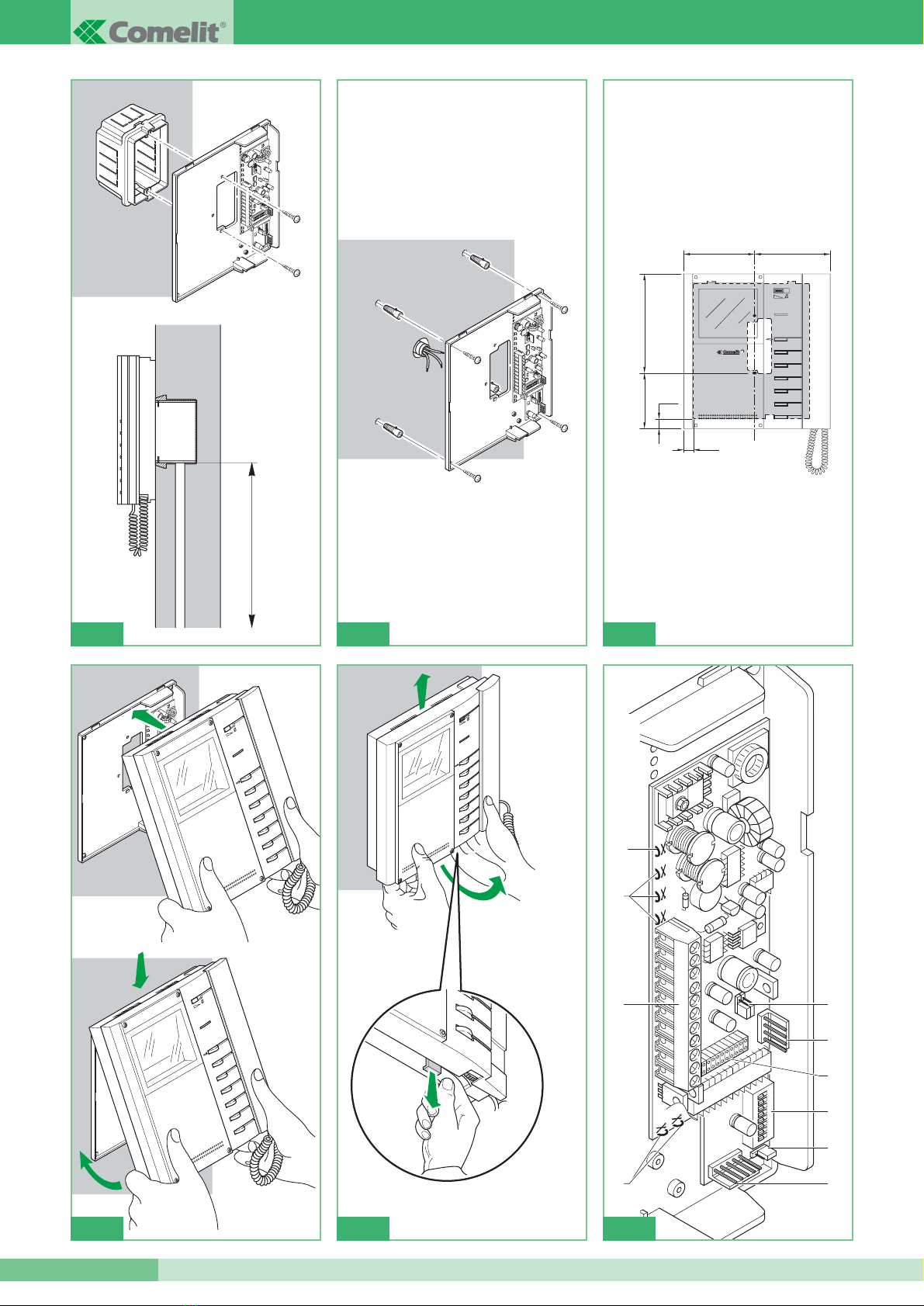
Fig. 1 Installazione Staffa Art. 5714 su scatola serie civile 503 (Art. 4517).
Fig. 2 Installazione a muro Staffa Art. 5714 con 4 viti a tassello. *
Fig. 3 Misure di ingombro del Monitor in relazione ai punti di fissaggio
della Staffa Art. 5714.
Fig. 4 Procedura di aggancio Monitor.
Fig. 5 Procedura per togliere il Monitor dalla staffa a cui è agganciato.
Fig. 6 1. Connettore Staffa-Monitor.
2. Morsettiera per connessione impianto:
+20 0 Morsetti per connessione con Art. 1205/B o 1212/B
L L Morsetti di connessione linea Bus.
CFP CFP Ingresso chiamata da piano.
P1 C1 Contatti per Pulsante 1 usato per usi vari.
Per avere un contatto NO (24V-100mA max) tagliare i
cavallotti CV3 e CV4.
S+ S- Morsetti per dispositivo ripetizione di chiamata.
3. JP1 Jumper per programmare la staffa come Principale o
Secondaria.
4. JP2 Jumper selezione tipo di funzionamento (Simplebus 1 o
Simplebus 2).
5. CN1 Connettore per schede opzionali Art. 5733, Art. 5734.
6. CN2 Connettore per programmazione.
7. S1 Micro-interruttori per programmazione codice utente.
8. CV1 CV2 CV7 Cavallotti alimentazione Monitor aggiuntivo.
9. CV3 CV4 Cavallotti da tagliare per liberare Pulsante 1 (contatto
NO 24V-100mA max).
10. CV5 Cavallotto chiusura video.
* Utilizzabile eventualmente anche con scatola serie civile 503
(Art. 4517) per migliorare il fissaggio della staffa.
Per informazioni complete su impianti Simplebus 2 (che utilizzano
quindi il miscelatore/alimentatore Art. 4896) fare riferimento al
manuale tecnico MT/SB2/01.
Fig. 1 Installation of Bracket Art. 5714 on civil series 503 box (Art. 4517).
Fig. 2 Installation on wall with Bracket Art. 5705 with 4 expansion
anchoring screws. *
Fig. 3 Overall dimensions of the Monitor in relation to the fixing points of
Bracket Art. 5714.
Fig. 4 Procedure for fixing the monitor to the back plate
Fig. 5 Procedure for removing the Monitor from the Bracket it is
hooked up to.
Fig. 6 1. Bracket-Monitor connector.
2. Terminals for system connection:
+20 0 Connection terminals Art. 1212/B or 1205/B.
L L Bus line connection.
CFP CFP local floor call input.
P1 C1 Connection terminal regarding Pushbutton 1 for various
uses. To have a clean NO contact (24V 100mA max), cut CV3
and CV4.
S+ S- Terminals for call repeater device.
3. JP1 Jumper to set bracket as Main or Secondary.
4. JP2 Jumper selection of type of operation (Simplebus 2 or
Simplebus 1).
5. CN1 Optional card (Art. 5733 or 5734) connector.
6. CN2 Programming connector.
7. S1 Dip Switches for programming user code.
8. CV1 CV2 CV7 additional Monitor power supply bridges.
9. CV3 CV4 bridges to free Pushbutton 1 (24V 100mA max).
10. CV5 Bridge for closing video.
* Can also possibly be used with civil series 503 box (Art. 4517) to
improve Bracket fixing.
For further information about Simplebus 2 System (System with
Art. 4896) please see MT/SB2/01.
Fig. 1 Installation Bride Art. 5714 sur le boîtier série civile 503 (Art. 4517).
Fig. 2 Installation en saillie Bride Art. 5714 à l’aide de 4 vis *
Fig. 3 Dimensions d’encombrement du moniteur par rapport aux points de
fixation de la Bride Art. 5714.
Fig. 4 Procédure de mise en place du moniteur.
Fig. 5 Procédure de retrait du moniteur de sa bride de fixation.
Fig. 6 1. Connecteur bride-moniteur.
2. Bornes de connexion à l’installation:
+20 0 Bornes de connexion Art. 1212/B ou 1205/B
L L Connexion ligne bus.
CFP CFP entrée appel du palier
P1 C1 Bornes de connexion Bouton 1 pour usages divers.
Pour avoir un contact libre NO, couper les cavaliers CV3
et CV4.
S+ S- Bornes pour le dispositif de répétition de l’appel.
3. JP1 Jumper pour la programmation de la Bride comme
Principal ou Secondaire.
4. JP2 Jumper de sélection du type de functionnement
(Simplebus 1 ou Simplebus 2)
5. CN1 Connecteur pour la carte Art. 5733 ou Art. 5734.
6. CN2 Connecteur pour la programmation de la Bride.
7. S1 Dip Switches pour la programmation du code usager.
8. CV1 CV2 CV7 Cavaliers d’alimentation du moniteur additionnel.
9. CV3 CV4 Cavalier pour dégager le Bouton 1 (24V 100mA max).
10. CV5 Cavalier de débranchement vidéo.
* S’utilise éventuellement aussi avec le boîtier série civile 503 (Art.
4517) pour améliorer la fixation de la bride.
Pour plus d’informations relatif à Simplebus 2 (système avec
Art. 4896) voir MT/SB2/01.
GB
F
GROUP S.P.A.
FT SB2 06 6
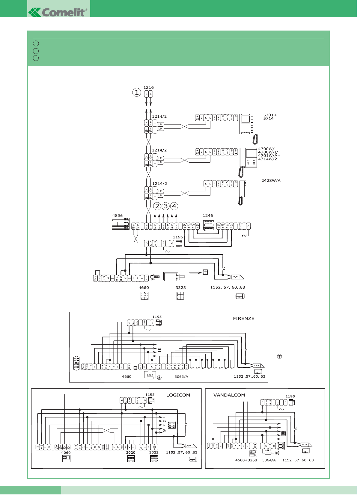
Impianto 1 porta video serie Powercom – Cablaggio Simplebus 2.
System with 1 Powercom Series video entrance – Simplebus 2 Cabling.
Installation avec 1 porte vidéo Série Powercom – Câblage Simplebus 2.
SB2V/01B
I
GB
F
Vedi FT SB2 04
See FT SB2 04
Voir FT SB2 04
FT SB2 06
7FT SB2 06
La somma totale del numero di posti interni con stesso codice utente e
del numero di dispositivi di ripetizione chiamata collegati ai suddetti
posti interni non può superare il numero di 4.
Connettere un solo dispositivo di ripetizione chiamata per ogni
posto interno. La distanza MAX del collegamento tra posto interno e
dispositivo di ripetizione chiamata è di 20 m;la ripetizione di chiamata
è attiva anche con funzione Privacy inserita.
Utilizzare cavo schermato per il collegamento e non far passare i cavi
in prossimità di carichi induttivi pesanti o cavi di alimentazione (230V /
400V).
Impostare l’Art. 1122/A per funzionamento a 12V. Connettere sui
contatti C-NO dell’Art. 1122/A solo dispositivi funzionanti in bassa
tensione. In caso di connessione di carichi induttivi si consiglia la
connessione di una capacità di 470nF in parallelo ai contatti C-NO
dell’Art. 1122/A.
The total sum of the number of internal units with the same user code
and of the number of call repetition devices connected to the
abovementioned internal units cannot exceed the number of 4.
Connect only one call repetition device for each internal unit. The
Max. distance of the connection between internal unit and call
repetition device is 20 m.
Call repetition is active also if Privacy service is activated.
Use shielded cable for the connection and do not make the cables
pass near heavy inductive loads or power supply cables (220V / 380V).
Set Art. 1122/A for operation at 12V. Only connect devices operating in
low voltage on the C-NO contacts of Art. 1122/A. In the case of
connection of inductive loads, connection of a capacity of 470nF in
parallel with the C-NO contacts of Art. 1122/A is recommended.
La somme du nombre de postes intérieurs ayant le même code usager
et du nombre de dispositifs de répétition d’appel branchés à ces
postes intérieurs ne peut pas être supérieur à 4.
Brancher un seul dispositif de répétition d’appel pour chaque poste
intérieur. La distance MAX de la connexion entre le poste intérieur et le
dispositif de répétition de l’appel est de 20 m.La répétition d’appel est
active si le service Privacy est activé aussi.
Pour la connexion, utiliser un câble blindé et ne pas faire passer les
câbles à proximité de charges inductives lourdes ou de câbles
d’alimentation (220V / 380V).
Programmer l’Art. 1122/A pour le fonctionnement à 12V. Brancher aux
contacts C-NO de l’Art. 1122/A seulement les dispositifs fonctionnant à
basse tension. En cas de connexion de charges inductives, la
connexion d’une capacité de 470nF en parallèle aux contacts C-NO de
l’Art. 1122/A est conseillée.
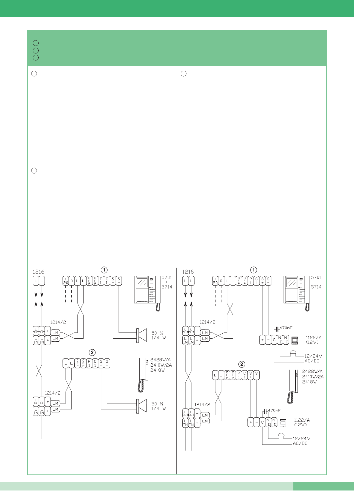
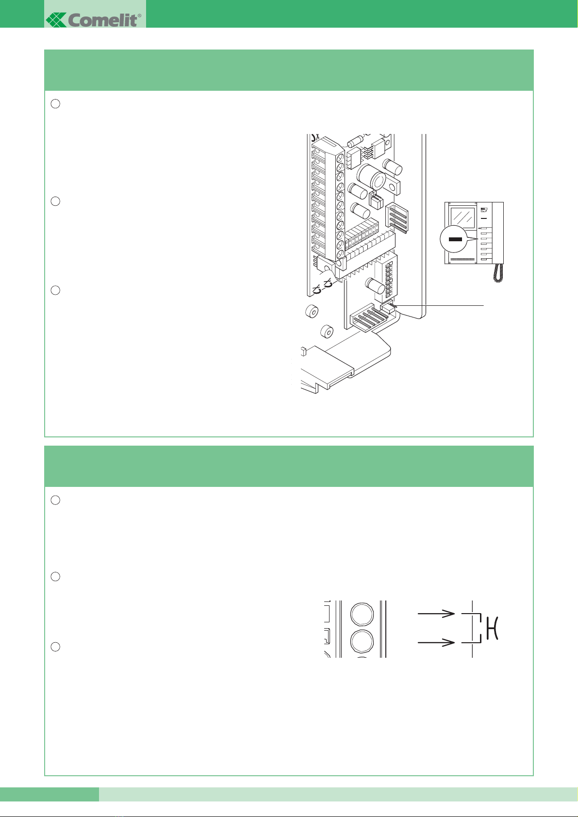
Connessione di dispositivi di ripetizione chiamata su staffa Art. 5714 e citofono Art. 2428W/A.
Connection of call repetition devices on bracket Art. 5714 and telephone Art. 2428W/A.
Connexion de dispositifs de répétition d’appel sur la bride Art. 5714 et sur le combiné parlophonique Art. 2428W/A.
SB2/V
I
GB
F
I
GB
F
GROUP S.P.A.
FT SB2 06 8
Fig. 3
VARIANTE A - VARIANT A - VARIANTE A
Utilizzo per usi vari del Pulsante 1 (contatto NO, max 24V 100mA) del
Monitor sulla staffa Art. 5714.
Application for various uses of Pushbutton 1 (NO contact, max 24V
100mA) of the Monitor on bracket Art. 5714.
Utilisation pour usages divers du bouton 1 (contact NO, max 24V
100mA) du moniteur sur la bride Art. 5714.
I
GB
F
I
VARIANTE B - VARIANT B - VARIANTE B
Utilizzo per usi vari del pulsante 2 del citofono Art. 2428W/A
(normalmente dedicato alla chiamata centralino).
Application for various uses of push-button 2 of telephone
Art. 2428W/A (normally dedicated to the switchboard call).
Utilisation pour usages divers du bouton 2 du combiné parlophonique
Art. 2428W/A (normalement destiné à l’appel du Hp-micro).
I
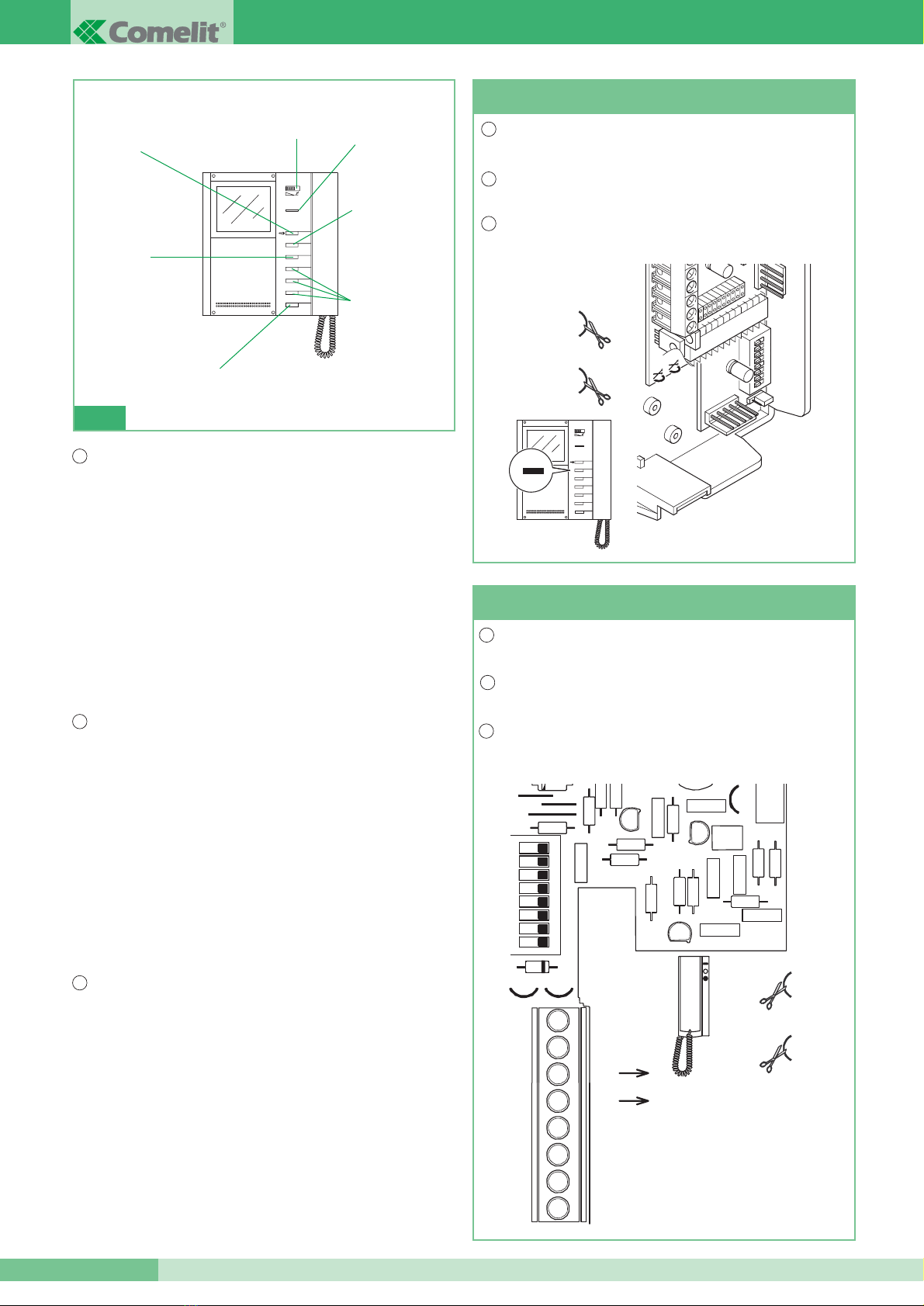
FUNZIONI ABBINATE AD OGNI PULSANTE
DEL MONITOR SERIE BRAVO
Il monitor della serie Bravo tramite la staffa Art. 5714 permette di avere di
serie le funzioni Apriporta, Chiamata a centralino di portineria e
Autoaccensione/Richiesta video.
Quelle in figura sono le impostazioni di fabbrica ma è comunque possibile
personalizzare le funzioni dei pulsanti programmando la staffa Art. 5714
tramite il programmatore palmare Art. 1251; per i dettagli sulle funzioni
programmabili e per procedere alla programmazione dei pulsanti del monitor
fare riferimento al Manuale tecnico MT/SB2/02 allegato all’Art. 1251.
I Pulsanti 3,4,5 e 6 sono disponibili con la scheda opzionale Art. 5733
mentre con la scheda opzionale Art. 5734 sono disponibili i Pulsanti 3 e 4 e
2 led di segnalazione nelle restanti posizioni.
FUNCTIONS COMBINEDWITH EACH PUSHBUTTON
OFTHE BRAVO SERIES MONITOR
By means of bracket Art. 5714, the monitor of the Bravo series allows a
series of functions: Door-release, Call to porter switchboard and Self-
lignition / Video request.
Those shown in the fdiagrams are the factory settings, but it is possible to
personalise the functions of the pushbuttons by programming bracket Art.
5714 by means of handheld programmer Art. 1251.
For details about the programmable functions and to proceed to programme
the monitor pushbuttons, please refer to technical Manual MT/SB2/02
enclosed with Art. 1251. Pushbuttons 3, 4, 5 and 6 are available with
supplementary card Art. 5733 whereas with supplementary card Art. 5734,
allows Pushbuttons 3 and 4 and 2 signalling LEDs to be available
FONCTIONS ASSOCIÉES A CHAQUE BOUTON
DU MONITEUR SÉRIE BRAVO
Au moyen de la bride Art. 5714, le moniteur de la série Bravo fournit les
fonctions d’Ouvre-porte, Appel au Hp-micro et Autoallumage/demande vidéo.
La figure illustre les programmations réalisées à l’usine, mais il est aussi
possible de personnaliser les fonctions des boutons en programmant le
combiné parlophonique la bride Art. 5714 avec le programmateur
palmaire Art. 1251.
Pour tout détail sur les fonctions programmables et pour programmer les
boutons du moniteur, voir le Manuel Technique MT/SB2/02 annexé à
l’Art. 1251.
Les boutons 3, 4, 5 et 6 sont disponibles avec la carte en option Art. 5733,
alors que la carte en option Art. 5734 permet de disposer des boutons 3 et
4, ainsi que de 2 leds de signalisation dans les positions restantes.
1
2
3
4
5
6
F
CV3
1 2 3 4
ON
5 6 7 8
DIP
CV4
CV3
CV4
1
2
3
4
5
6
1
CV2
CV2
1 2 3 4 5 6 7 8
CV3CV1
CV3
S -
C1
P1
CFP
CFP
L
L
MAX 24V - 100mA
S +
2
LED
Chiamata a centralino
Call to switchboard
Appel au Hp-micro
Attuatore generico
Generic actuator
Actionneur générique
Selettore suoneria / servizio Privacy.
Bell / Privacy service selector.
Sélecteur sonnerie /service Privacy
Apriporta
Door-opener
Ouvre-porte
Autoaccensione /
Richiesta video
Self-lignition /
Video request
Autoallumage /
demande vidéo
Funzione Dottore
Doctor Facility
Service Docteur
GB F
GB
FT SB2 06
9FT SB2 06
VARIANTE C
VARIANT C
VARIANTE C
Funzione Autoaccensione (solo per impianti con 1 o 2 ingressi) su monitor con staffe Art. 5714 impostate come Principali (vedi JP1 di figura, in
posizione P). La funzione di Autoaccensione deve essere abilitata.
Abilitare/disabilitare la funzione Autoaccensione: per abilitare la funzione è necessario tener premuto il pulsante 2 del monitor (se mantenute le
impostazioni di fabbrica) o il pulsante programmato tramite Art. 1251 per questa funzione per un tempo superiore a 4 sec.
All’avvenuta impostazione si ode, portando la cornetta all’orecchio, un duplice tono di conferma. Per disabilitare tener premuto lo stesso pulsante per
un tempo superiore a 4 sec. In questo caso si ode, portando la cornetta l’orecchio, un singolo tono di conferma.
Utilizzo dell’ autoaccensione: l’accensione del monitor avviene (se la funzione è stata abilitata) premendo e rilasciando immediatamente il pulsante 2
(se mantenute le impostazioni di fabbrica) o il pulsante programmato tramite Art. 1251 per questa funzione.
Self-lighting function (only for systems with 1 or 2 entrances) on monitor with brackets Art. 5714 set as Main (see JP1 in the figure, position P).
The Self-lighting function must be enabled. Enabling/disabling the Self-lighting function: to enable the function, pushbutton 2 of the monitor must be
kept pressed (if the factory settings are kept), or the pushbutton programmed by means of Art. 1251 for this function for more than 4 seconds.
Once setting has taken place, by lifting the receiver to your ear, a double confirmation tone is heard.
To disable the function, keep the same pushbutton pressed for more than 4 seconds. In this case, by lifting the receiver to your ear, a single
confirmation tone is heard.
Use of self-lighting: the monitor lights up (if the function has been enabled) by pressing and immediately releasing pushbutton 2 (if the factory
settings are kept) or the pushbutton programmed by means of Art. 1251 for this function.
Fonction d’auto-allumage (seulement pour les installations avec 1 ou 2 plaques de rue) sur un moniteur, avec les brides Art. 5714 programmées
comme Principales (voir JP1 sur la figure, position P).
La fonction d’auto-allumage doit être validée. Validation/Invalidation de la fonction d’auto-allumage : pour valider cette fonction, appuyer de manière
continue sur le bouton 2 du moniteur (si les programmations faites à l’usine ont été maintenues) ou appuyer sur le bouton programmé avec l’Art.
1251 pour cette fonction, pendant plus de 4 sec.
Cette programmation est confirmée par l’émission d’une double tonalité de validation, dans le récepteur.
Pour invalider cette fonction, appuyer sur ce même bouton pendant plus de 4 secondes.
Dans ce cas, vous entendrez une seule tonalité de confirmation dans le récepteur. Utilisation de la fonction d’auto-allumage: si cette fonction a été
validée, pour allumer le moniteur, appuyer et relâcher immédiatement le bouton 2 (si les programmations faites à l’usine ont été maintenues) ou
appuyer sur le bouton programmé avec l’Art. 1251 pour cette fonction.
I
GB
F
JP1
CV3
1 2 3 4
ON
5 6 7 8
DIP
CV4
1
2
3
4
5
6
2
GROUP S.P.A.
FT SB2 06 10
VARIANTE D
VARIANT D
VARIANTE D
Richiesta Video su monitor con staffe Art. 5714 impostate come
Secondario (vedi JP1 di figura, in posizione S).
La funzione di Richiesta video non richiede abilitazione; essa permette
di accendere un monitor in seguito ad una chiamata da posto
esterno per l’utente.
Utilizzo della funzione Richiesta Video: l’accensione del monitor
avviene premendo e rilasciando immediatamente il pulsante 2 (se
mantenute le impostazioni di fabbrica) o il pulsante programmato
tramite Art. 1251 per questa funzione.
Video Request on monitor with brackets Art. 5714 set as Secondary
(see JP1 in the figure, position S).
The video Request function does not need enabling. It allows a monitor
to be lit up following a call for the user from the external unit.
Use of the Video Request function: the monitor lights up by pressing
and immediately releasing pushbutton 2 (if the factory settings are
kept), or the pushbutton programmed by means of Art. 1251 for this
function.
Allumage écran du moniteur avec les brides Art. 5714 programmées
comme Secondaire (voir JP1 dans la figure, position S)
La fonction de visualisation écran ne requiert aucune validation, elle
permet de brancher un moniteur après un appel usager venant de la
plaque de rue.
Utilisation de la fonction de visualisation écran: pour brancher le
moniteur, appuyer sur le bouton 2 et le relâcher immédiatement (si les
programmations faites à l’usine ont été maintenues) ou appuyer sur le
bouton programmé avec l’Art. 1251 pour cette fonction.
I
GB
F
VARIANTE E
VARIANT E
VARIANTE E
Utilizzo della chiamata da piano sulle staffe Art. 5714.
I monitor con il medesimo codice utente suonano contemporaneamente
su chiamata da piano.
Utilizzo della chiamata da piano sul citofono Art. 2428W/A.
I citofoni con il medesimo codice utente suonano contemporaneamente
su chiamata da piano.
La distanza massima del collegamento deve essere di 20 m.
Use of the local floor call on brackets Art. 5714.
The monitors with the same user code ring at the same time on a
floor door call.
Use of the local floor call on telephone Art. 2428W/A.
The telephones with the same user code ring at the same time on a
local floor call. The max distance of the connection is 20 m.
Utilisation de l’appel palier sur les brides Art. 5714.Les moniteurs
ayant le même code usager retentissent en même temps lors de
l’appel palier palier.
Utilisation de l’appel palier sur le combiné parlophonique
Art. 2428W/A.Les combinés parlophoniques ayant le même code
usager retentissent en même temps lors d’un appel palier.
La distance maximum de la connexion entre le BP d’appel palier et le
récepteur est de 20 ml.
I
GB
F
CFP
CFP
JP1
C
CV3
1 2 3 4
ON
5 6 7 8
DIP
CV4
1
2
3
4
5
6
2
FT SB2 06
11 FT SB2 06
Seguire la seguente procedura per variare le suonerie del Monitor:
1Tenere premuto il Pulsante fino a che non verrà emesso un suono di conferma (l’operazione è possibile solo con l’impianto in situazione di
riposo; in caso contrario il led di segnalazione lampeggerà per avvisare l’utente).
2Premere e rilasciare il Pulsante :
1 volta (viene emesso un tono di conferma) per modificare la suoneria di chiamata da posto esterno.
2 volte (vengono emessi 2 toni di conferma) per modificare la suoneria di chiamata da centralino.
3 volte (vengono emessi 3 toni di conferma) per modificare la suoneria del campanello di piano.
Ulteriori pressioni del Pulsante ripetono la sequenza appena descritta.
Dopo l’ultima pressione del Pulsante attendere un suono di conferma selezione prima di passare alla fase seguente.
3Premere e rilasciare il Pulsante per scorrere in sequenza le varie suonerie disponibili. Nel caso si voglia riascoltare più volte la stessa
suoneria mantenere premuto il Pulsante .
4Sollevare e riagganciare la cornetta per confermare la scelta dell’ultima suoneria ascoltata e per uscire (in qualunque momento) dalla modalità di
variazione suoneria Monitor.
All’uscita dalla modalità di variazione suoneria Monitor verrà emesso un suono di conferma.
Follow the procedure below to change the Monitor call tones:
1Keep the Pushbutton pressed until a confirmation tone is heard (this operation is only possible with the system in the stand-by situation;
otherwise the signalling LED will flash to warn the user that this is not so).
2Press and release the Pushbutton:
Once: (1 confirmation tone is given) to change the tone of a call from the external unit.
Twice: (2 confirmation tones are given) to change the switchboard call tone.
Three times: (3 confirmation tones are given) to change the local floor call tone. Any further pressing on the key repeats the sequence
described above. After the last time the Pushbutton is pressed, wait for a confirmation tone before passing on to the following stage.
3Press and release the Pushbutton to scroll the various tones available in sequence. If you want to hear the same tone several times, keep
the Pushbutton pressed.
4Lift the handset and put it back down to confirm selection of the last bell heard and to exit (at any time) from the Monitor call tone variation mode.
On exiting from the Monitor a confirmation tone will be given.
Pour varier la sonnerie du moniteur, suivre la procédure ci-dessous:
1Maintenir appuyé le Bouton jusqu’à ce qu’une tonalité de confirmation soit audible (cette opération n’est possible que lorsque le système est
en condition de repos; dans le cas contraire, la led de signalisation clignote pour avertir l’utilisateur).
2Appuyer et relâcher le Bouton :
1 fois (émission d’une tonalité de confirmation) pour modifier la sonnerie d’appel de la plaque de rue.
2 fois (émission de 2 tonalités de confirmation) pour modifier la sonnerie du Hp-micro.
3 fois (émission de 3 tonalités de confirmation) pour modifier la sonnerie de l’appel palier.
Appuyer ultérieurement sur la Bouton pour répéter en séquence les opérations décrites ci-dessus.
Après le dernier appui sur le Bouton , attendre la tonalité de confirmation de la sélection avant de passer à l’étape suivante.
3Appuyer sur le Bouton et le relâcher pour faire défiler en séquence les différentes sonneries disponibles. Si vous désirez écouter plusieurs
fois la même sonnerie, maintenir appuyé le Bouton .
4Décrocher le récepteur et le raccrocher pour confirmer le choix de la sonnerie choisie.
Une tonalité de confirmation vous avertira que vous avez quitté le mode de programmation de la sonnerie Moniteur.
I
GB
F
Variazione suonerie monitor.
Changing monitor Call tones.
Programmation sonneries moniteur.
I
GB
F

GROUP S.P.A.
FT SB2 06 12
CV5
CV2
CV7
CV1
CV3
1 2 3 4
ON
5 6 7 8
DIP
CV4
CV2
CV7
CV1
JP2
CV1
CV7
CV2
1
JP2
2
S1
S2
Fig. 7 Come impostare la Staffa 5714 per funzionamento in Simplebus 1 (il funzionamento in Simplebus 1 non prevede l’utilizzo dell’Art. 4896).
Fig. 7 How to set Bracket 5714 for operation in Simplebus 1 (operation in Simplebus 1 does not foresee the use of Art. 4896).
Fig. 7 Comment régler la bride 5714 pour fonctionner avec les systèmes Simplebus 1 (le fonctionnement en Simplebus 1 ne prévoit pas
l’utilisation de l’Art. 4896).
I
GB
F
Fig. 7
Posizionare JP2 come in figura.
Set jumper JP2 as shown in the picture.
Placer JP2 comme illustré dans la figure.
Tagliare CV1, CV2 e CV7.
Cut CV1, CV2 and CV7.
Couper CV1, CV2 et CV7.
SIMPLEBUS 1
SIMPLEBUS 1
SIMPLEBUS 1
UTILIZZARE LE PAGINE SEGUENTI SOLO PER IMPIANTI SIMPLEBUS 1
(CHE NON UTILIZZANO QUINDI L’ART. 4896). PER ULTERIORI INFORMAZIONI SU SIMPLEBUS 1
FARE RIFERIMENTO A MT/SB2/01 3° EDIZIONE O FT/SB/07.
THE FOLLOWING PAGES MUST BE USED ONLY REGARDING SIMPLEBUS 1 SYSTEMS
(WITHOUT ART. 4896). FOR FURTHER INFORMATION ABOUT SIMPLEBUS 1
PLEASE SEE TECHNICAL MANUAL MT/SB2/01 3° EDITION OR FT/SB/07.
DOCUMENTATION TECHNIQUE À UTILISER SEULEMENT
POUR L’INSTALLATION DE SYSTÈMES SIMPLEBUS 1 (SYSTÈME SANS ART. 4896)
POUR PLUS D’INFORMATIONS RELATIF À SIMPLEBUS 1 VOIR MT/SB2/01 3° ÉDITION OU FT/SB/07.
ATTENZIONE - WARNING - ATTENTION
FT SB2 06
13 FT SB2 06
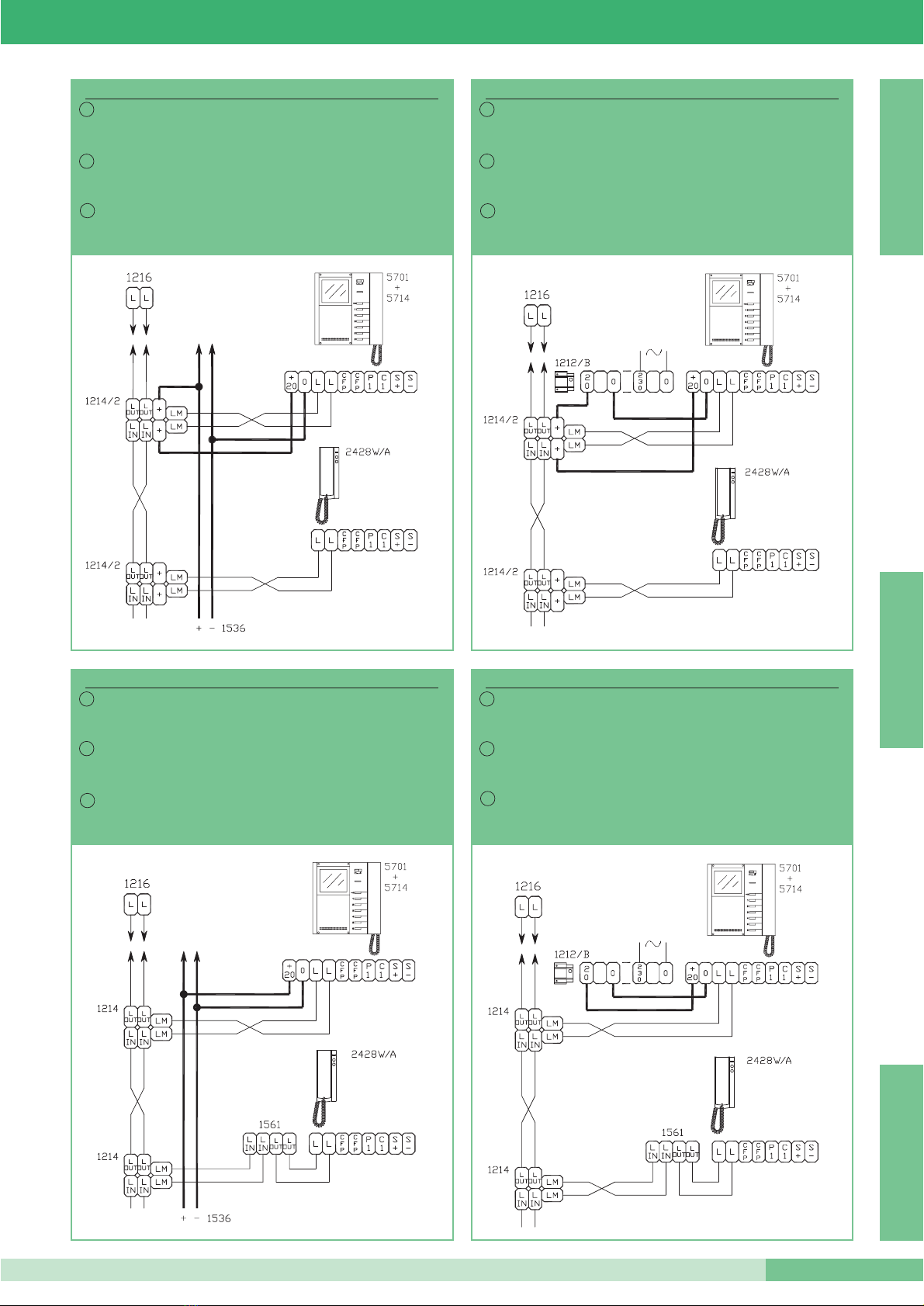
SB2/U1
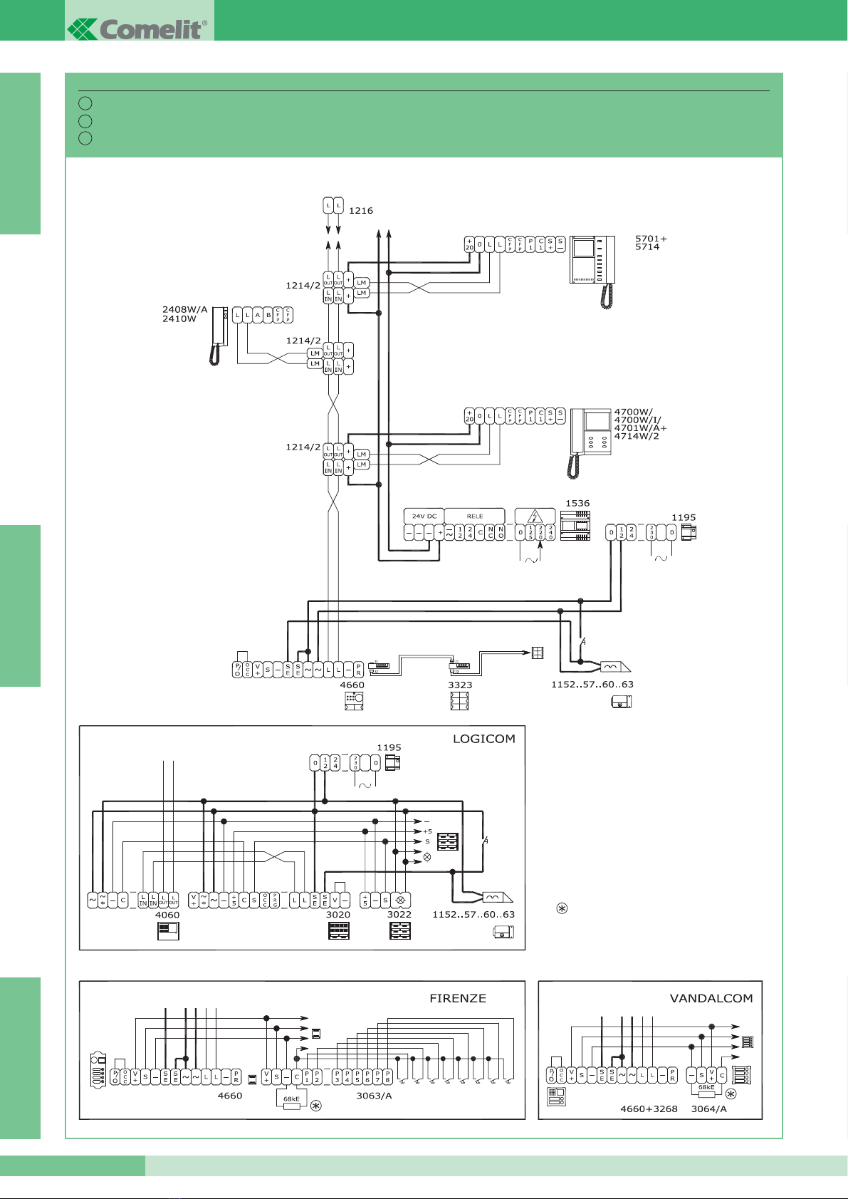
Connessione 2428W/A e 5714 in impianti misti
Simplebus1 con alimentazione tramite 1536
e con morsetto di derivazione 1214/2.
How to connect 2428W/A and 5714 in mixed audio
and video Simplebus1 systems powered with 1536
and with distribution terminal 1214/2.
Connexion de l’Art. 2428W/A et de l’Art. 5714
dans des installations mixtes Simplebus1, alimentées
par l’Art. 1536 et avec borne de dérivation 1214/2.
F
GB
I
SB2/U2
Connessione 2428W/A e 5714 in impianti misti
SImplebus1 con alimentazione tramite 1212/B
e con morsetto di derivazione 1214/2.
How to connect 2428W/A and 5714 in mixed audio
and video Simplebus1 systems powered with 1212/B
and with distribution terminal 1214/2.
Connexion de l’Art. 2428W/A et de l’Art. 5714 dans des
installations mixtes Simplebus1, alimentées
par l’Art. 1212/B et avec borne de dérivation 1214/2.
F
GB
I
SB2/U3
Connessione 2428W/A e 5714 in impianti misti Simplebus1
con alimentazione tramite 1536 e con morsetto
di derivazione 1214 e scheda blocco video 1561.
How to connect 2428W/A and 5714 in mixed audio and
video Simplebus1 systems powered with 1536, with
distribution terminal 1214 and card for video block 1561.
Connexion de l’Art. 2428W/A et de l’Art. 5714 dans des
installations mixtes Simplebus1, alimentées par l’Art. 1536,avec
borne de dérivation 1214 et carte pour blocage écran 1561.
F
GB
I
SB2/U4
Connessione 2428W/A e 5714 in impianti misti
Simplebus1 con alimentazione tramite 1212/B e con
morsetto di derivazione 1214 e scheda blocco video 1561.
How to connect 2428W/A and 5714 in mixed audio and
video Simplebus1 systems powered with 1212/B, with
distribution terminal 1214 and card for video block 1561.
Connexion de l’Art. 2428W/A et de l’Art. 5714 dans des
installations mixtes Simplebus1, alimentées par l’Art. 1212/B,
avec borne de dérivation 1214 et carte de coupure vidéo 1561.
F
GB
I
SIMPLEBUS 1SIMPLEBUS 1SIMPLEBUS 1
GROUP S.P.A.
FT SB2 06 14
Impianto 1 porta video serie Powercom – Cablaggio Simplebus 1.
System with 1 Powercom Series video entrance – Simplebus 1 Cabling.
Installation avec 1 porte vidéo Série Powercom – Câblage Simplebus 1.
SBV/02B
I
GB
F
SIMPLEBUS 1
SIMPLEBUS 1
SIMPLEBUS 1
Vedi FT SB2 04
See FT SB2 04
Voir FT SB2 04

FT SB2 06
15 FT SB2 06
NOTE - NOTES - NOTE

FT/SB2/06 – 1aedizione 09/2005 – cod. 22590279
Comelit Group S.p.A. - Via Don Arrigoni 5 - 24020 Rovetta S. Lorenzo BG Italy - tel. (+39) 0346 750 011 - fax (+39) 0346 71436
15, Rue Jean Zay
69800 Saint Priest
Tel 04 72 28 06 56
Fax 04 72 28 83 29
http://www.comelit.fr
E-mail: [email protected]
CERTIFICAZIONE DEI SISTEMI
QUALITA' DELLE AZIENDE
UNI EN - ISO 9001:2000
F
Aventurijn 220
3316LB Dordrecht
Tel 078 65 11 201
Fax: 078 61 70 955
http://www.comelit.nl
E-mail: [email protected]
NL
Chaussée de Ninove, 900
1703 Schepdaal (Dilbeek)
Ninoofsesteenweg, 900
1703 Schepdaal (Dilbeek)
Tel 02 411 50 99 - Fax 02 411 50 97
http://www.comelit.be
E-mail: [email protected]
B
1 Brownfields
Welwyn Garden City
HERTS - AL7 1AN
Tel 01707 377203
Fax 01707 377204
http://www.comelitgroup.co.uk
E-mail: [email protected]
UK SG
SINGAPORE
REPRESENTATIVE OFFICE
53 Meyer Road - Meyer Tower #19-00
Singapore 437878
Tel:+65-6440 5857
Fax: +65 6440 5136
E-mail: [email protected]
Josef Estivill 67/69
08027 Barcelona
Tel. 932 430 376
Fax 934 084 683
http://www.comelit.es
E-mail: [email protected]
E
This manual suits for next models
1
Popular Telephone manuals by other brands


Yealink
Yealink T46S Skype for Business user guide

Deutsche Telekom
Deutsche Telekom T_Octopus F200 operating instructions

Radio Shack
Radio Shack 4-Line System Speakerphone with Caller ID and Headset... owner's manual

Ameriphone
Ameriphone JV-35 operating instructions

Mitel
Mitel MiVOICE BUSINESS Quick reference guide

Samsung
Samsung OfficeServ 7200 System description