Simplex 2120 User manual

2120 Multiplex
Expanded Transponder
--
Troubleshooting Guide
@ 1996 Simplex Time Recorder Co., Gardner. Mass. 01441-0001 U.S.A.
MUX2-61-002
Ed 10 86
firealarmresources.com

CAUTION
ELECTRICAL HAZARD
Oiinnecf elecbical power when making any internal
adjustments or repairs. Installation and servicing
should be performed by qualiied Simplex Representa-
tives
CAUTION
POWERING REQUIREMENT
When removing power from thii system, disconnect
batteries FIRST and AC power last. When connecting
power to this system, connect AC power FIRST and
batteries last.
I I
firealarmresources.com

INTRODUCTION
HOW TO USE THIS PUBLiCATlON
This publication contains troubleshooting procedures for 2120 expanded transponders (ETs).
Note: Refer to 2120 Expanded Transponder General Information for background information on 2120 ETs.
When troubleshooting an ET, you should have the following documents on hand:
l
A copy of the specific ET’s cabinet drawing, supplied with the system. This drawing will show you the
equipment configuration of a specific ET.
l
A copy of the specific 2120 Expanded Transponder Functions Sheet (M-1320).
l
2120 Multiplex Troubleshooting Guide.
l
2120 Multiplex Jumper Placement and Switch Settings.
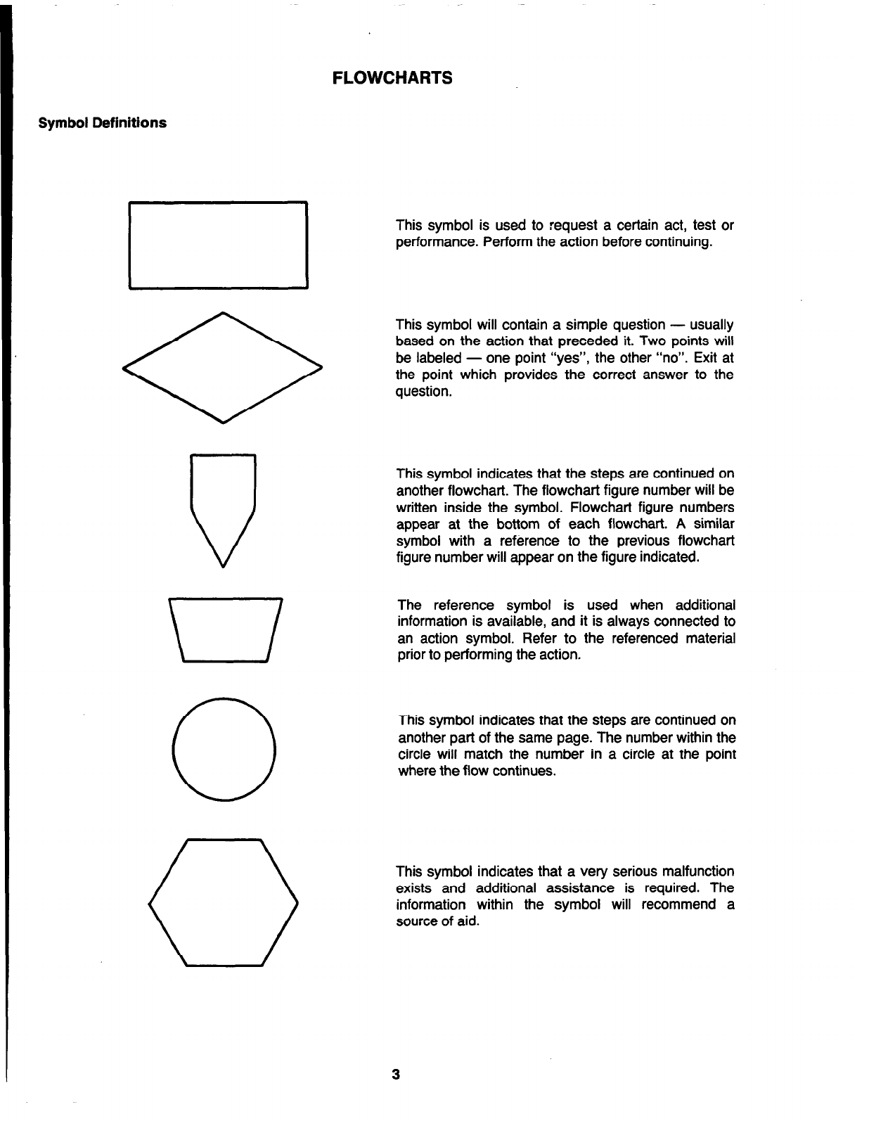
This guide uses flowcharts to help you efficiently isolate ET troubles. Each flowchart is given a figure number;
designations such as “Figure 1A” or “Figure 3C” indicate that there is a group of figures associated with a
particular troubleshooting procedure. Any given flowchart contains all the information necessary to perform any
tests or checks called out on that flowchart. Follow.the flowcharts exactly, and when you reach a figure reference
- PROCEED DIRECTLY TO THE REFERENCED FIGURE.
WHEN TO USE THIS PUBLICATION
Your troubleshooting procedures should always begin in the 2120 Multiplex Troubleshooting Guide to avoid
being misled by “obvious” trouble symptoms. You will refer to the ET troubleshooting guide under the following
conditions:
l
You have reached the Transponder Flowchart in the 2120 Multiplex Troubleshooting Guide and you have
monitor or control point troubles on an ET.
l
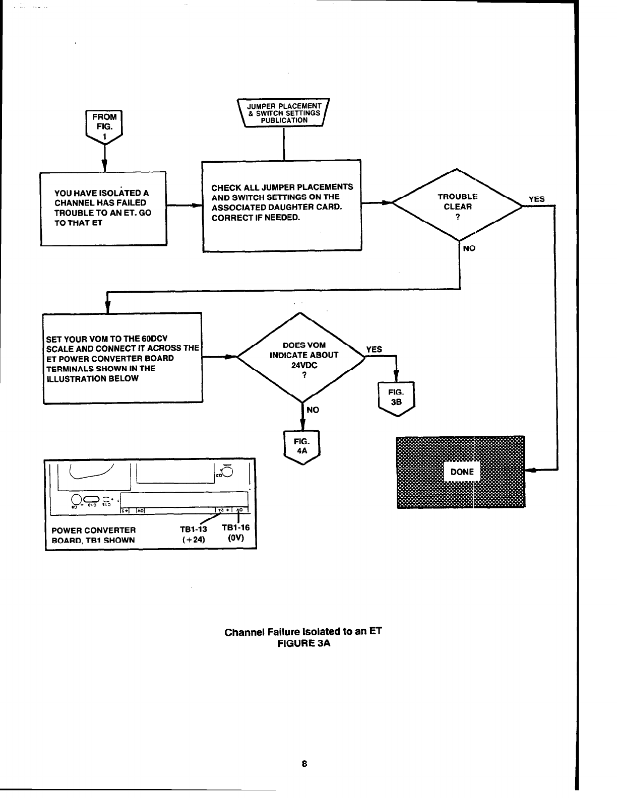
You have begun troubleshooting a communications problem (i.e., CHANNEL HAS FAILED) in the
Transponder Flowchart and you have isolated the problem to an ET.
l
You have an ET power supply problem (POWER/BATTERY FAIL or GROUND FAULT trouble message).
l
One of the following troubles refer to an ET:
- XPNDR COM FAILED PRI
- XPNDR COM FAILED SEC
l
One or more ET monitor points are locked in alarm.
l
The trouble message OPEN LINE LOC SWITCH is reported.
You should always begin the ET troubleshooting procedures with Figure 1.
firealarmresources.com

ADDITIONAL INFORMATION
Only certain I/O boards can be used with any one daughter card. For that reason, you shoulld know which l/O
boards are used with each ET daughter card. Table A lists compatible ET daughter and I/O cards.
TABLE A
Compatible ETDaughter and I/OCards
DAUGHTER CARD
digitalmonitor board, 562448 COMPATIBLE I/O BOA.RDS
digital monitor I/Oboard,562-390
voltage monitor I/Oboard,562-398
firealarm digital monitor board, 562-506
firealarm digital monitor board
(ClassA), 562-465
digitalcontrol boardwith supervision, 562-445
fire alarmdigital monitor l/O board,562505
fire alarmdigital monitor l/Oboard
(Class A)562-466
standard (12OV)relay I/Oboard,562-447
audio relayI/Oboard (ClassA),562-450
simultaneous audio relay I/Oboard,562-508
digitalcontrol boardwithout standard (12OV)relay I/Oboard,562-447
supervision, 562-459 240V relayI/Oboard,562-392
2
firealarmresources.com

Symbol Definitions
.
u
\
0
0
FLOWCHARTS
This symbol is used to request a certain act, test or
performance. Perform the action before continuing.
This symbol will contain a simple question - usually
based on the action that preceded it. Two points will
be labeled - one point “yes”, the other “no”. Exit at
the point which provides the correct answer to the
question.
This symbol indicates that the steps are continued on
another flowchart. The flowchart figure number will be
written inside the symbol. Flowchart figure numbers
appear at the bottom of each flowchart. A similar
symbol with a reference to the previous flowchart
figure number will appear on the figure indicated.
The reference symbol is used when additional
information is available, and it is always connected to
an action symbol. Refer to the referenced material
priorto performing the action.
This symbol indicates that the steps are continued on
another part of the same page. The numberwithin the
circle will match the number in a circle at the point
where the flow continues.
This symbol indicates that a very serious malfunction
exists and additional assistance is required. The
information within the symbol will recommend a
source of aid.
firealarmresources.com

CAUSED YOUCAUSED YOU
TO REFERENCE THISTO REFERENCE THIS
TROUBLESHOOTINGTROUBLESHOOTING
ET MONITOR OR CONTROL POINT TROUBLES
FIG.
U
2A
ZHANNEL HAS FAILED TROUBLE HAS BEEN
SOLATED TO AN ET
POWER/BATTERY FAIL TROUBLE
I + ,
FIG.
U
4A
GROUND FAULT TROUBLE
h
t
I
I
I-
/
1
I
,
<PNDR COM FAILED PRI FOR AN ET
FIG.
U
5A
r I
FIG.
6A
v
KPNDR COM FAILED SEC FOR AN ET
t FIG.
U
6A
ONE OR MORE ET MONlTOR POINTS LOCKED IN ALARM
GO TO THE BASIC
FLOWCHART IN THE
2120 MULTIPLEX
TROUBLESHOOTlMG
GUIDE
2-l
OPEN LINE LOC SWITCH TROUBLE
Starting Point
FIGURE 1
4
firealarmresources.com

FROM
FIG.
*
t
GO TO THE ET
REPORTING THE
CONTROL
POINT
MONITOR
ET Monitor and Control Point Troubles
FIGURE 2A
5
firealarmresources.com

CHECK ALL JUMPER PLACEMENTS
AND SWITCH SETTINGS ON THE
MORE THAN ONE POINTS ON THE ASSOCIATED DAUGHTER CARD
(AND I/O BOARD, IF APPROPRIATE)
CORRECT IF NEEDED
t
,I
CHECK EXTERNAL MONITOR CHECK HARNESS BETWEEN
POINT WIRING FOR SHORTS I/O BOARD AND
OR OPENS. REPAIR AS ASSOCIATED DAUGHTER
APPROPRIATE CARD
a-
I NO
* TROUEILE
<>
CLEA.R
?
YES
I
‘ES
c
’ 1
-I
c
REPLACE
HARNESS
0
1
NO
?
1
REPLACE
I10 BOARD
ET Monitor and Control Point Troubles
FIGURE 26
6
firealarmresources.com

CHECK ALL JUMPER PLACEMENTS
YES AND SWITCH SElTlNGS ON THE
MORE THAN ONE POINTS ON THE _ . ASSOCIATED DAUGHTER CARD.
CORRECT IF NEEDED.
I
CHECK EXTERNAL CONTROL
POINT WIRING FOR SHORTS
OR OPENS. REPAIR AS
APPROPRIATE.
REPLACE DAUGHTER
CARD
REPLACE
HARNESS
REPLACE
110 BOARD
ET Monitor and Control Point Troubles
FIGURE 2C
7
firealarmresources.com

YOU HAVE ISOLATED A
CHANNEL HAS FAILED I
TROUBLE TO AN ET. GO
TO THAT ET
f
CHECK ALL JUMPER PLACEMENTS
AND SWITCH SETTINGS ON THE
ASSOCIATED DAUGHTER CARD.
,CORRECT IF NEEDED.
NO
SET YOUR VOM TO THE GODCV
SCALE AND CONNECT IT ACROSS THE
ET POWER CONVERTER BOARD
TERMINALS SHOWN IN THE
ILLUSTRATION BELOW
INDICATE ABOUTINDICATE ABOUT
,tz+, ,o
I
‘OWER CONVERTER ‘TBl-16
TBl-13
IOARD, TBl SHOWN (+24) W)
Channel Failure Isolated to an ET
FIGURE 3A
firealarmresources.com

FROM ’
FIG.
SET YOUR VOM TO THE 3DVC
SCALE AND CONNECT IT DOES LEVEL
ACROSS THE POINTS
INDICATED IN THE
ILLUSTRATION BELOW
FIG.
REMOVE POWER TO THE ET RECONNECT POWER TO THE ET
AS FOLLOWS: REMOVE ALL ET AS FOLLOWS:
. DISCONNECT BAlTERIES ’
DAUGHTER CARDS . CONNECTAC FIRST.
FIRST. . CONNECT BAlTERlES
. DISCONNECT AC LAST. LAST.
CONNECT YOUR VOM
ACROSS THE POINTS
INDICATED IN THE
ILLUSTRATION BELOW
.
FIG.
3c
TO BLACK LEAD
OF VOM
ET
CPU
BOARD
RED LEAD OF,
VOM TO PIN 2
OF IC16
Channel Failure Isolated to an ET
FIGURE 38
9
firealarmresources.com

REPLACE THE
CPU BOARD’S
MICROPROCESSOR
REPLACE THE ET
CPU BOARD
(SEE NOTE BELOW)
t t
YOU HAVE A POSSIBLE
FAULT IN THE ET’S
OPERATING PROGRAM
FOLLOW AELD
ECHELON SUPPORT
PROCEDURE IN
GENERAL SERVICE
LETTER #M-83
Note: When you replace the ET’s CPU board,
carefully remove all ICs located in sockets IC2
through IC9. (Be sure to note which socket
each IC mounts in.) Then, carefully plug the
ICs into their proper positions on the
replacement CPU board.
Channel Failure Isolated
to
an ET
FIGURE 3C
10
firealarmresources.com

c
REMOVE POWER TO THE ET
AS FOLLOWS:
. DISCONNECT BAlTERIES FIRST.
. DISCONNECT AC LAST.
L
I I I I
i
RE-INSTALL ONE-HALF OF
THE REMOVED DAUGHTER
CARDS
H
RECONNECT POWER TO THE
ET AS FOLLOWS:
l
CONNECT AC FIRST.
. CONNECT BAlTERlES LAST.
J I
SET YOUR VOM TO THE
3DCV SCALE AND
CONNECT CTACROSS DOES LEVEL
THE POINTS SHOWN IN
THE ILLUSTRATION
BELOW
REMOVE POWER TO REINSTALL ONE-HALF OF
THE ET - THE REMAINING
DAUGHTER CARDS
c
I
I I I
RECONNECT POWER TO THE
ET
t-
CONNECT YOUR VOM
ACROSS THE POINTS
SHOWN IN THE
ILLUSTRATlON BELOW
TO BLACK LEAD
OF VOM ,OV = TBl-5
ET
CPU
BOARD
RED LEAD OF
VOM TO PIN 2
DF lCl8 .
I ml Id i :- d-l-:
Channel Failure Isolated to an ET
FIGURE 3D
11
firealarmresources.com

FROM
FIG.
3D,3F
ONE OF THE DAUGHTER
CARDS YOU JUST
INSTALLED IS CAUSING
THE TROUBLE
t-
PERFORM HALF-SPLllTING ON THE
CARDS JUST INSTALLED. MEASURE
ACROSS THE POINTS SHOWN IN THE
ILLUSTRATION BELOW. WHEN THE
LEVEL EGUALS OV, YOU’VE FOUND
THE BAD CARD.
REPLACE THE
FAULTY ET
DAUGHTER CARD
TO BLACK LEAD
OF VOM
ET
CPU
BOARD
RED LEAD OF,
VOM TO PIN 2
OF IC18
Channel Failure Isolated to an ET
FIGURE 3E
12
firealarmresources.com

FROM
FIG.
30
P
REINSTALLED ALL
REMAINING DAUGHTER
1
YES
INSTALL REMAINING
. DAUGHTER CARDS 1
ET
CPU
BOARD
RED LEAD OF,
VOM TO PIN 2
OF IC18
SET YOUR VOM TO THE 3DCV
SCALE AND CONNECT lT ACROSS
THE POINTS SHOWN IN THE
ILLUSTRATION BELOW
TO BLACK LEAD
Channel Failure Isolated to an ET
FIGURE 3F
firealarmresources.com

SET YOUR VOM TO THE 3DVC
SCALE AND CONNECT lT
ACROSS THE POINTS
INDICATED IN THE
ILLUSTRATION BELOW
FIG.
REMOVE POWER TO THE ET
AS FOLLOWS:
. DISCONNECT BAlTERlES - REMOVE ALL ET
FIRST; DAUGHTER CARDS
l
DISCONNECT AC LAST.
I I
L
RECONNECT POWER TO THE ET
AS FOLLOWS:
. CONNECT AC: FIRST.
l
CONNECT BATTERIES
LAST.
I
I
CONNECT YOUR VOM
ACROSS THE POINTS
INDICATED IN THE
ILLUSTRATION BELOW
ET
CPU
BOARD
RED LEAD OF,
VOM TO PIN 8
OF IC18
TO BLACK LEAD
Channel Failure Isolated to an ET
FIGURE 3G
14
firealarmresources.com

FROM
FIG.
36
P
REMOVE POWER TO THE ET
AS FOLLOWS:
. DISCONNECT BAlTERlES
FIRST.
. DISCONNECT AC LAST.
RE-INSTALL
UNI
---E-HALF OF
1
RECONNECT POWER TO THE
__._-..--- -
THE REMOVED DAUGHTER I ET AS FOLLOWS:
. CONNECT AC FIRST.
CARDS . CONNECT BATTERIES LAS1
I
SET YOUR VOM TO THE
3DCV SCALE AND CONNECT
IT
ACROSS
THE POINTS
SHOWN IN THE ILLUSTRA-
TION BELOW
I
REMOVE POWER TO
H
REINSTALL ONE-HALF OF
THE ET THE REMAINING
DAUGHTER CARDS
H
CONNECT YOUR VOM
RECONNECT POWER TO THE ACROSS THE POINTS
ET SHOWN IN THE
ILLUSTRATION BELOW
J
ET
CPU
BOARD
RED LEAD OF
VOM TO PIN 8
OF IC18
TO BLACK LEAD
OF VOM = TB13
Channel Failure Isolated to an ET
FIGURE 3H
15
firealarmresources.com

t
I I
REPLACE THE
FAULTY ET
DAUGHTER CARD
TO BLACK LEAD
OF VOM OV = TBl-5
I
ET
CPU
BOARD
READ LEAD OF,
VOM TO PIN 8
OF IC18
.
Channel Failure Isolated to an ET
FIGURE35
Ed884
16
575585
firealarmresources.com

REINSTALLED ALL INSTALL REMAINING
DAUGHTER CARDS
i
SET YOUR VOM TO THE 3DCV
SCALE AND CONNECT lT ACROSS
THE POINTS SHOWN IN THE
ILLUSTRATION
11 fl
FIG.
3J FIG.
3L
~-
TO BLACK LEAD
OF VOM
ET
CPU
BOARD
RED LEAD OF,
VOM TO PIN 8
OF lCl8
Channel Failure Isolated to an ET
FIGURE 3K
17
firealarmresources.com

FROM
FIG.
CHECK IC2 THROUGH IC9
ON THE ET CPU BOARD FOR
BENT PINS OR IMPROPER
SEATING. CAREFULLY CORRECT
IF NEEDED.
REPLACE THE CPU
BOARD’S MICRO-
PROCESSOR
REPLACE THE ET’S
CPU BOARD.
(SEE NOTE BELOW)
I
Note:
When you replace the ET’s CPU board, qwe-
fully remove all ICs located in sockets IC2
through IC9. (Be sure to note which socket
each IC mounts in.) Then, carefully plug the
ICs into their proper positions on the replace-
ment CPU board.
FOLLOW FIELD
PROCEDURE IN
GENERAL SERVICE
LETTER #14-83
Channel Failure Isolated to an ET
FIGURE 3L
18
firealarmresources.com
Other manuals for 2120
8
Table of contents
Other Simplex Marine Radio manuals
Popular Marine Radio manuals by other brands

Standard Horizon
Standard Horizon HX400 owner's manual

Humminbird
Humminbird Marine Radio user manual

DIGITAL YACHT
DIGITAL YACHT NOMAD Installation and instruction manual

Furuno
Furuno AIS Transponder FA-50 Operator's manual

NAUTICAST
NAUTICAST X-Pack DS user manual

ACR Electronics
ACR Electronics PATHFINDER 3 manual