manuals.online logo
Brands
  1. Home
  2. •
  3. Brands
  4. •
  5. Simplicity
  6. •
  7. Accessories
  8. •
  9. Simplicity 6 User manual

Simplicity 6 User manual

Other manuals for 6

1

Other Simplicity Accessories manuals

Simplicity Snow Cab 1694921 Datasheet

Simplicity

Simplicity Snow Cab 1694921 Datasheet

Simplicity 1687099 User manual

Simplicity

Simplicity 1687099 User manual

Simplicity 795 User manual

Simplicity

Simplicity 795 User manual

Simplicity 335 User manual

Simplicity

Simplicity 335 User manual

Simplicity 891 User manual

Simplicity

Simplicity 891 User manual

Simplicity Landlord Riding Tractor User manual

Simplicity

Simplicity Landlord Riding Tractor User manual

Simplicity 665 User manual

Simplicity

Simplicity 665 User manual

Simplicity Light Kit 454 User manual

Simplicity

Simplicity Light Kit 454 User manual

Simplicity TV CO-AXIAL SOCKET User manual

Simplicity

Simplicity TV CO-AXIAL SOCKET User manual

Popular Accessories manuals by other brands

Quincy lab 140AE-1 operating manual

Quincy lab

Quincy lab 140AE-1 operating manual

HomePro ZIR000 user manual

HomePro

HomePro ZIR000 user manual

DOL 20SCR Technical user guide

DOL

DOL 20SCR Technical user guide

RAB Smart Task installation manual

RAB

RAB Smart Task installation manual

Kemppi KMS 300 quick guide

Kemppi

Kemppi KMS 300 quick guide

Stearns 57,500 Series Installation and service instructions

Stearns

Stearns 57,500 Series Installation and service instructions

iGuzzini TWILIGHT COPENAGHEN manual

iGuzzini

iGuzzini TWILIGHT COPENAGHEN manual

Adelaide Annexe & Canvas Avan Deluxe installation guide

Adelaide Annexe & Canvas

Adelaide Annexe & Canvas Avan Deluxe installation guide

OHAUS 5000 instruction manual

OHAUS

OHAUS 5000 instruction manual

HOME8 WLS1300 quick start guide

HOME8

HOME8 WLS1300 quick start guide

MAXBOTIX MaxSonar quick start guide

MAXBOTIX

MAXBOTIX MaxSonar quick start guide

ioSmart iSmart56 Installation and user guide

ioSmart

ioSmart iSmart56 Installation and user guide

Focusrite Scarlett 18i8 user guide

Focusrite

Focusrite Scarlett 18i8 user guide

Velleman ED38105 user manual

Velleman

Velleman ED38105 user manual

JumpSport SkyBounce user manual

JumpSport

JumpSport SkyBounce user manual

Prima-Temp PRIYA Instructions for use

Prima-Temp

Prima-Temp PRIYA Instructions for use

Tefcold BC85I-BC85I W user manual

Tefcold

Tefcold BC85I-BC85I W user manual

Vaisala WMS302 user guide

Vaisala

Vaisala WMS302 user guide

manuals.online logo
manuals.online logoBrands
  • About & Mission
  • Contact us
  • Privacy Policy
  • Terms and Conditions

Copyright 2025 Manuals.Online. All Rights Reserved.

Installation Guide
Simplicity 6
V4.0 lu060318
Tools Required
Below is a list of tools that you will require to install the Simplicity 6 Canopy or Carport.
Cordless Drill Mastic Gun Spirit Level Tape Measure 8mm Spanner
8mm Socket
& Ratchet
5mm & 6.5mm
Drill Bit
White Rubber
Mallet
Pozi Head
Screwdriver
& Flathead
Hammer
Digging
Equipment
Aluminium
Chop Saw
Roofing Square 36” Sash Cramp
10mm Spanner
10mm Socket
& Ratchet
45mm
Hole Saw
Gutter Extrusion Post Extrusion Roof Bar Extrusion End Roof Bars Wall Plate Gutter Trim
Height 110mm
Wall Plate End Plate
Height 130mm
Gutter End Plate Glass Sheets Glass End
Enclosures
5/8 Pozi Self
Tapping Screws
Type AB
6mm x 16mm
Pan Pozi
Screw Bolt
M6 Nylock Nut No. 12x 1 ¼”
Hexagon Self
Drill Screws
No. 10x 25mm
Hexagon Drill
Screws
Glazing Bar
End Plate
Gallow Support Bar
Hex Headed Bolts
Bolt Down Post
Foot Above
Ground (if required)
In Ground Post
Foot (if required)
2No. Joining Plate
18mm x 300mm x 2mm
Joining Plate
61.5mm x 300mm x 2mm
Joining Plate
70mm x 300mm x 2mm
Spigot
Parts Supplied
Below is a list of the parts supplied with your new canopy. Please check that all parts are present
before commencing the installation process.
2
M6 X 20MM
*Please refer to your CAD drawing for each individual order as this will show the roof bar spacing
as per your order. This installation guide is generic and the centre's spacing is given as a guide
example only.
Materials NOT supplied with your system:
Wall Plate Fixings Bolt Down Post Fixings Concrete or Material for ‘making good’ Lead Flashing
Patination Oil Electrical Cable for LED Lighting connection Cleaning Materials
....
...
Preliminary Stages and Planning
Below is a roof span chart which you MUST refer to in order to establish the maximum centre to
centre dimensions of your roof bars and posts.
Before starting your install please check all components for quantity and damage.
PLEASE NOTE – A MAXIMUM OF 500MM OVERHANG ON THE GUTTER IS ALLOWED
500mm Max Overhang on the
Guttering from Post 500mm Max Overhang on the
Guttering from Post
SPAN Chart Roof
Bars
Up to 3.2m
Projection
System 6
600mm Roof Bar
Spacings
POST SPACINGS
Up to & Including
3.2m Projection
System 6 3m Post Spacings
PLEASE NOTE, IF USING SELF CLEANING GLASS A MINIMUM PITCH OF 10°IS REQUIRED.
At 3.2 metres projection the maximum pitch of your roof system is 13° due to glass length, contact
the office for further details.
Be aware! You must ensure all glass is installed with the film facing upwards (sky). This will ensure
that if installing self cleaning glass it is the correct way up.
Please note when ordering Pilkington Self Cleaning Glass:
Pilkington Activ™ needs both daylight and rain to work effectively. When the roof angle gets too low
the rain does not wash the loosened dirt off as effectively. A good flow of water across the glass is
beneficial. Pilkington Activ™ still gives better results than ordinary glass with low angle roof
applications. We recommend a minimum angle of 10 degrees.
You are now ready to start installing the structure, following all steps within this guide.
Lighting (if required)
The lighting consists of an aluminium extrusion that can fit to either the bottom of the wall plate, or
the back of the gutter beam. When installing lighting please consider cable exist and cable entry to
the light channel. The lighting also comes with an electrical capacitor for each 6m of light and an
optional external grade plastic box to house the capacitors if the installation requires that they be
mounted outside.
3
4
STEP 1
Foundation Hole Positions for Posts
Establish the height of the canopy/carport at the back (wall edge) and the height of the canopy at
the front. The height at the front must be above 2.1m to meet the minimum legal head height
requirement.
Once you have established your height at the front and back, deduct the height at the front from the
height at the back to give you “The Fall” (x). Measure distance 'x' up the wall and position your roof
bar at this height on the wall. Let the other end touch the ground and where that touches will be the
centre of your hole for the foundation.
IMPORTANT: Use roofing square to ensure the bar used is held square to the wall.
STEP 2
Digging of Holes
You can either cast foundations first or dig holes for casting after. (Bolt to or cast in)
Holes or foundations must be a minimum of 300x300x600 deep. This is only a guide. Please
consult a structural engineer for verification
5
STEP 3
Fitting of Wall Plate to the Wall
Measure 30mm in from one end of the Wall plate and approx 55mm down from the top of the inside
profile and mark before you drill. Drill the wall plate using the correct sized drill bit for the suitable
wall fixings that you intend to use (not supplied). Once this is done repeat at the other end.
Continue to drill holes in the wall plate at approx 55mm down and at approx 300mm centres. This is
only a guide. Please consult a structural engineer for verification. See diagram
You must ensure the wall plate is not twisted or bowed. Use a spirit level to make sure the wall plate
is fitted level.
Using suitable wall fixings, fix the wall plate to the wall, we recommend plastic caps are fitted over
the screw/bolt heads for aesthetic reasons.
Centralise the post foot to the post and attach using 2 x No. 12 x 1 ¼” self drill screws
STEP 4
Fitting of Post Feet to Posts
(Note the
post foot is only suitable for surface mounting the posts. If your posts need to be concreted
into the ground please follow step 4a overleaf)
STEP 4a
Fitting of Post Feet to Posts
Centralise the post anchor to the post and attach using 2 x No12 x 1 ¼” self drill screws
6
STEP 5
Cutting the Posts
STEP 6
Fitting of Post to Gutter Section
Measure the height of the canopy/carport at the front and add to this dimension the depth of post
that will be going into the ground. The total of this is the length at which your posts needs to be cut.
Position the gutter section over the posts and ensure they are in the correct position and are spaced
in accordance with the span chart. Ensure the post is square to the gutter section using a roofing
square. Using 2 x No. 12 x 1 ¼” drill screws, secure through the front profile of the gutter into the
post. Repeat on the inner side so that 4 screws in total are used to secure the post.
STEP 7
If your canopy or carport is longer than 6m, you may need to join the gutter sections as
follows:
Joining Gutter Sections
You will need the following to join every gutter beam:
4No. flat aluminium joining plates: 2No. 18mm x 300mm x 2mm, 1No. 70mm x 300mm x 2mm, 1No.
61.5mm x 300mm x 2mm
1No tube of Sudaflex marine grade sealer
1No roll of masking tape
4No. M6 x 20mm hex headed bolts
4No. M6 self locking nuts
1No. 6.5mm drill bit
1No mastic gun
1No drill with 8mm self driller attachment
Industrial wipes
Roll of industrial tissue paper
1. Make sure you only use ; normal silicon sealer will not do.
2. Now apply a liberal amount of Sudaflex to both sides of the eave beam on
the internal vertical sections and the underside of the gutter where the
plate fits into this will enable you to bond the four joining plates.
Sudaflex
3. Flatten any excess Sudaflex with the spatula and apply a generous amount of sealer around
every edge of both plates. Then insert all plates half way in to one half of the join.
4. Apply ample amounts of Sudaflex across all corresponding areas of the opposite gutter
beam
5. You are now ready to marry the two gutter beams together but you must ensure they are flat
and level to each other.
6. Once you have married the two beams together you must leave at least a
6a. Drill 2 No. x 6.5mm holes through the top 18mm joining plate and gutter channel and either
side of the join line at the back of the Gutter Channel. Using the 6mm Hex Headed Bolts and
Nuts supplied bolt through the gutter channel and joining plates and tighten up.
7. After around 15 to 20 minutes and once the sealer has had time to harden stand the gutter
beam with legs attached up, and attach the bars as described in the above procedure.
8. Once your canopy is glazed, your legs are plumb and your gutter beam is level up and
down, left and right, and front to back, ensure your gutter is dry and the surface temperature
at least 4 degrees. If you are installing in the winter, you may need to use a heat gun.
9. Then you will need to apply the final amount of Sudaflex into the bottom of the gutter beam,
please see diagrams below:
3mm gap between the two but no greater than 5mm
3mm gap
between the two but no greater than 5mm
7
10. Apply a generous amount around the edges of the flat plates inside the gutter and
ensure all gaps are filled with Sudaflex internally.
STEP 8
Stand Post & Gutter Beam Up
Using the excavated hole, position each of the posts into the centre of the hole and lean the whole
frame forward so that the back of the posts leans against the front of the hole; please see diagram
overleaf.
If the posts are to be surface mounted, please secure the posts ensuring they are plum and square.
STEP 9
Fitting of the Glazing Bars
Pre-drill the glazing bar that is going to fit into the gutter section. 15mm in from the edge and 30mm
from the end of the bar drill your 6.5mm hole. Do this on both sides of the bar. This will allow the
glazing bar to overhang the gutter section. Please see the images below.
8
STEP 7a
Fitting the Gallows Support Bar
The gutter support bar is designed to span from post to post or from post to end cap underneath
the gutter, fix the bar through the gutter channel using self drillers every 300mm both sides of the
gutter as shown in the below diagram.
9
Make sure the glazing bar is in line with the gutter beam, then using the same fixing method as the
wall plate secure the glazing bar to the gutter section. Your pre-drilled holes will determine where
you drill through on the radius of the gutter section. Please see diagram below:
Repeat the above with the last glazing bar at the other end of the wall plate and gutter beam to
stabilise the wall plate and gutter beam while you seal the wall plate in the following section.
DO NOT FIT ANY MORE GLAZING BARS AT THIS STAGE
Starting with the End Glazing Bar, push this bar into the wall plate so that it is pushed back as far as
possible and ensure the outside profile lines up with the edge of the wall plate. Rest the other end of
the glazing bar on the radius inner section of the gutter section.
Using a 6.5mm drill bit, drill 1 No. hole through the bottom radius profile of the wall plate ensuring
this also goes through the flat section of the glazing bar. Locate a 6mm x 16mm pan pozi screw bolt
through the hole and apply m6 nyloc nut. Using an 8mm ratchet and screw driver tighten up.
Repeat this process on the other side of the glazing bar. Please see the image below:
STEP 10
Sealing Wall Plate Against the Wall
STEP 11
Glass Sheets
If flashing or silicone is required to seal the wall plate against the wall, it needs to be done prior to
the glass sheets being fitted.
The glass sheet comes with a protective film fitted on the coated face. This needs to be removed
prior to fitting. The side with the film needs to be fitted facing the sunlight.
PLEASE NOTE IF USING SELF CLEANING GLASS A MINIMUM PITCH OF 10°IS REQUIRED.
10
STEP 12
Glazing the Canopy
The glass will be supplied cut to the correct dimensions needed for the installation.
When you push the glazing bar into the wall plate the gasket will have a tendency to fold back. You
need to flick the rubber gasket out so it lips over the glazing bar and glass.
The glass into the glazing should be a nice, tight fit. You will need to apply a suitable lubricant to the
top and bottom gasket prior to inserting the glass. (Not supplied) We suggest fairy liquid.
Always fit the glass into the next glazing bar at floor level before you lift and position into the fixed
bar on the frame.
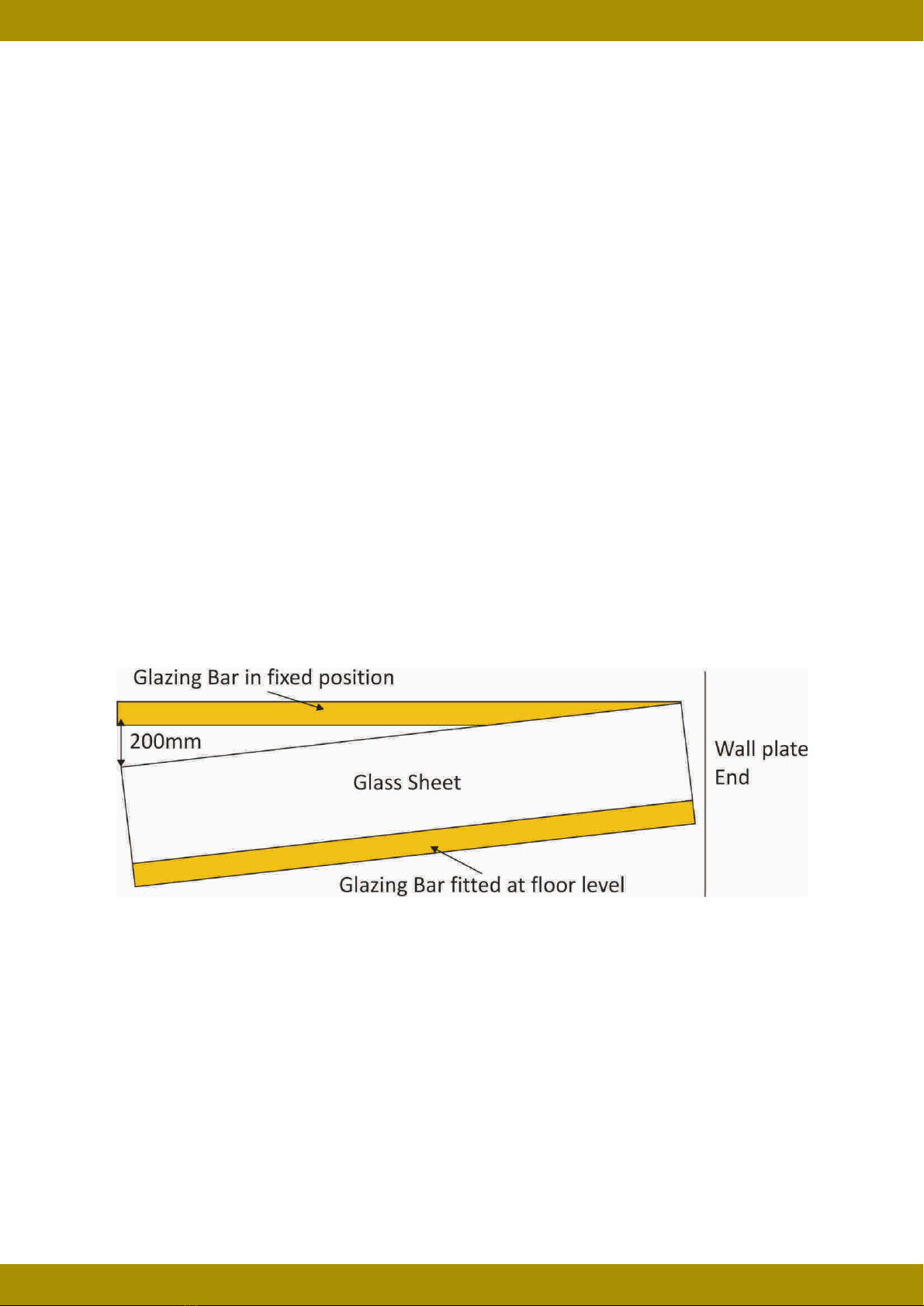
When you are fitting the glass sheet into the fixed glazing bar (with the next bar attached) it is
recommended that you locate the top corner into position first with the other end about 200mm
away from the finished position. When the glass is located in this position it is recommended that
you use a Sach Cramp or rachet straps to ensure the glass stays within the glazing bar and does
not spring out while you are pushing the glass into the bar. Then working from that top corner you
steadily work along pushing the glass into the glazing bar which reduces the gap until the full length
of glass is located into the glazing bar. See illustration below
Secure the glazing bar in place as shown in STEP 9
STEP 13
Fitting of the ‘F’-Section
Secure the glazing bar to the gutter section using M6 X 16MM Pan Pozi Bolts and M6 Nuts.
Ensure the end of the glass is fitting flush with the edge of the glazing bars as shown overleaf.
The glass is 40mm wider than the inside to inside measurement of the roof bars as a rule.
Please refer to your CAD drawing at this stage as this will show you the inside to inside
glazing bar dimension. Measure your glass to ensure it is 40mm wider than this dimension.
The glass is therefor designed to locate 20mm inside each glazing bar. This allows for a 5mm
gap between the centre of the bar and the glass, which is an allowance for any expansion.
The F section is supplied pre cut to the correct width of the inside to inside glazing bar dimension.
Please measure this width and check against your CAD drawing.