SimpliPhi PHI 3.8 Series User manual

Power.On YourTerms.
PHI 3.8™, PHI 2.9™,
PHI 1.4™ & PHI 730™ Battery Models
INSTALLATION MANUAL
Optimized Energy Storage & Management for Residential & Commercial Applications Utilizing
Efficient, Safe, Non-Toxic, Energy Dense Lithium Ferrous Phosphate (LFP) Chemistry
© SIMPLIPHI POWER, INC. REV073019
INSTALLATION MANUAL

SimpliPhi Power, Inc. | 3100 Camino Del Sol | Oxnard, CA 93030, USA | (805) 640-6700 | info@simpliphipower.com | SimpliPhiPower.com
| 2 |
SimpliPhi’s battery technology utilizes the industry’s most
environmentally benign chemistry combined with proprietary
architecture and power electronics (BMS) that eliminate the
need for cooling or ventilation to create products that provide
energy security and resiliency –all with a 98% efficiency rate.
SimpliPhi Your
Energy Security and
Independence
and gain control of your own power.
SimpliPhi Power helps you manage your power as a personal
resource. Anytime. Anywhere. SimpliPhi energy storage
optimizes integration of any power generation source –solar,
wind, generator –on or off grid, and protects your home and
mission-critical business functions from power outages and
intermittency. SimpliPhi storage technology eliminates operating
temperature constraints, toxic coolants and the risk of thermal
runaway and fire. Safe lithium ferrous phosphate (LFP). No
cobalt. No hazards.
SimpliPhi Power offers proprietary, commercially availableenergy storage
and management systems that are safe, non-toxic, reliable, durable, efficient,
highly scalable, and economical over the lifetime of the PHI Battery.

REV073019
SimpliPhi Power, Inc. | 3100 Camino Del Sol | Oxnard, CA 93030, USA | (805) 640-6700 | info@simpliphipower.com | SimpliPhiPower.com
| 3 |
Table of Contents
1.0 –Important Safety Information ......................................................................................... 4
1.1 –Safety Instructions ...................................................................................................... 4
1.3 –Explosive Gas Precautions......................................................................................... 7
2.0 –Product Description........................................................................................................ 7
2.1 –Overview ...................................................................................................................... 7
2.2 –Specifications .............................................................................................................. 8
3.0 –Pre-Installation................................................................................................................ 9
3.1 –PHI Battery Performance Parameters and Sizing...................................................... 9
Calculations.......................................................................................................................... 9
3.2 –System Sizing for Your Installation............................................................................ 9
3.3 –Mounting Hardware ..................................................................................................... 9
3.4 –Battery Weight ............................................................................................................. 9
3.5 –Battery Wall Mount + Bracket Dimensions ...............................................................10
4.0 –Installation & Wiring.......................................................................................................11
4.1 –Basic System Configuration Concepts.....................................................................11
4.2 –Torque Values.............................................................................................................13
4.3 –Battery Wiring Methods..............................................................................................13
4.4 –Battery Bank Expansion.............................................................................................15
5.0 –Programming..................................................................................................................16
5.1 –Operating Parameters per Warranty..........................................................................16
6.0 –SimpliPhi Technical Support.........................................................................................17
Appendix A –PHI Battery Safety & Green Attributes, Certifications...................................18
Appendix B –PHI Approved External Chargers ...................................................................20
Appendix C –PHI Legacy Battery Parameters......................................................................21

REV073019
SimpliPhi Power, Inc. | 3100 Camino Del Sol | Oxnard, CA 93030, USA | (805) 640-6700 | info@simpliphipower.com | SimpliPhiPower.com
| 4 |
1.0 –Important Safety Information
1.1 –Safety Instructions
1. Before using the PHI Batteries, read all instructions and cautionary markings on the PHI Batteries,
and all appropriate sections of this manual.
2. PHI Batteries must be fully charged before commissioning (i.e. before connecting loads). Failure to
do so will void the Warranty.
3. Use of accessories not recommended or sold by the manufacturer may result in a risk of fire, electric
shock, or injury to persons and will void the Warranty.
4. Verify system settings are in compliance with the PHI Battery Warranty and this PHI Battery
Installation Manual (which take precedence). Violating Warranty conditions specified in these
documents will void the Warranty on the PHI Batteries.
5. Consult the Integration Guide for Inverter and Charge Controller programming settings for relevant
warnings and notices. Violating Warranty conditions specified in those Inverter Integration Guides
will void the Warranty on the PHI Batteries, not just the inverter equipment. Consult SimpliPhi Power
Technical Support regarding any inconstancies with other referenced documents.
6. Although each PHI Battery contains an internal BMS with circuitry that protects the PHI Battery cells
from overcharge, over-discharge and extreme load amperage, the PHI Batteries must always be
installed with appropriate inverter and charge controller settings and power electronics to protect the
PHI Battery from open PV voltage and other high voltage charging sources. Do not attempt to
replace existing power electronics without SimpliPhi’s written approval. Failure to adhere to
installation protocol will void the Warranty.
7. Verify polarity at all connections with a standard volt meter before 1) energizing the system and 2) on
batteries with threaded stud connections, before switching the built-in circuit breaker to the “ON”
position. Reverse polarity at the PHI Battery terminals will void the Warranty and destroy the PHI
Batteries.
8. PHI Batteries pose some risk of shock or sparking during the installation and initial wiring and
connection process. This is consistent with all other battery-based storage formats. For batteries with
threaded stud connections, be sure the built-in circuit breaker is in the “OFF” position to minimize the
risk of shock or sparks during the installation and commissioning of the system.
9. To avoid a risk of fire and electric shock, make sure that existing wiring is in good condition and that
wire is not undersized. Do not operate the unit with damaged or substandard wiring.
10. Do not operate if the PHI Battery has been damaged in any way during shipping or otherwise.
11. Only use a SimpliPhi approved LFP battery charger if ancillary charging is required before
installation, testing or troubleshooting. Failure to use a SimpliPhi approved LFP battery charger will
damage the PHI Battery and void the Warranty. See Appendix C for a complete list of approved
chargers.
12. To reduce the chance of short-circuits, always use insulated tools when installing or working with this
equipment.
13. Remove personal metal items such as rings, bracelets, necklaces, and watches when working with
electrical equipment.
REV073019
SimpliPhi Power, Inc. | 3100 Camino Del Sol | Oxnard, CA 93030, USA | (805) 640-6700 | info@simpliphipower.com | SimpliPhiPower.com
| 5 |
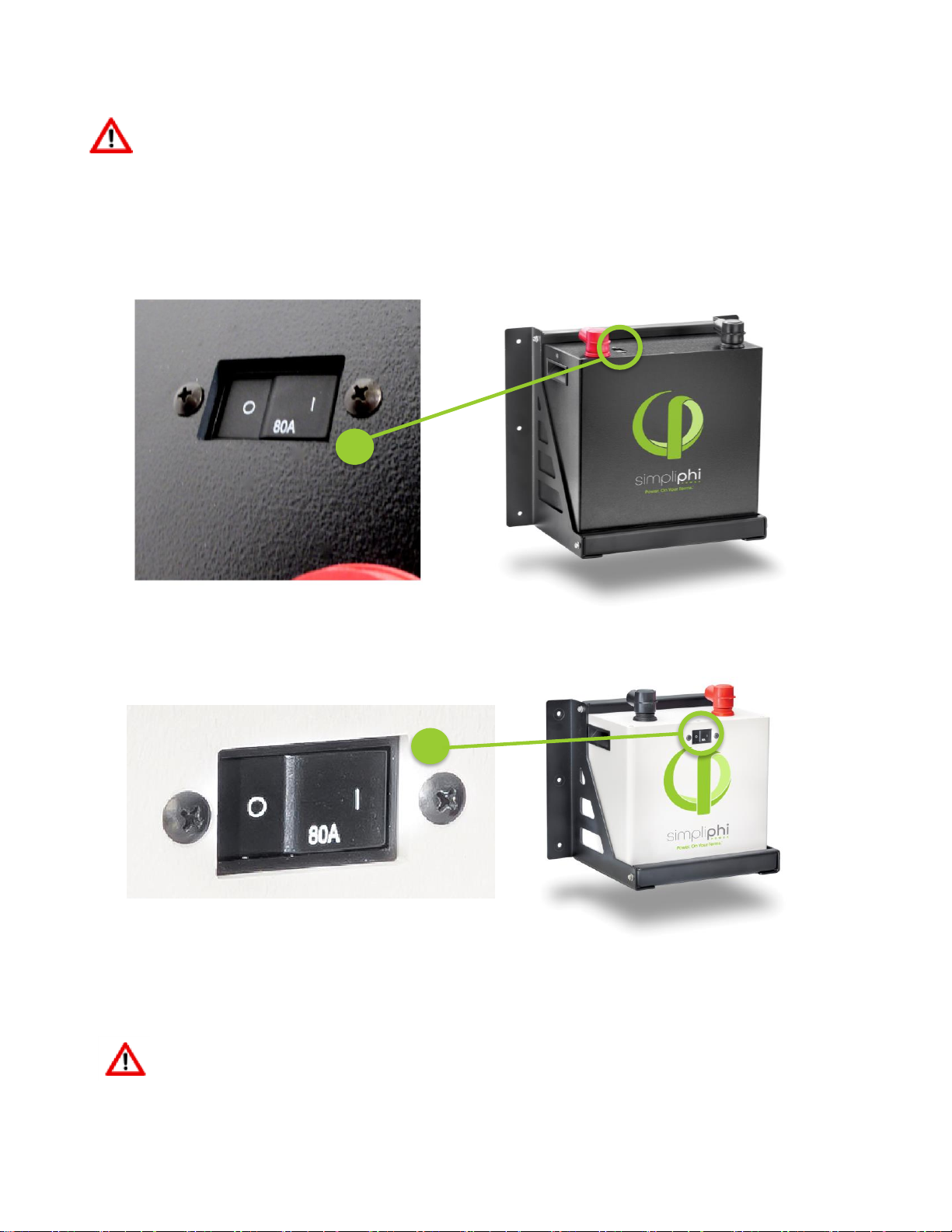
1.2 –Safety & Protective Features
1.2.1 –Breaker
Each PHI battery with threaded stud connections is outfitted with a hydraulic/magnetic circuit
breaker. This breaker increases safety during shipping and installations and allows the battery to
effectively be turned “OFF” or “ON.” The breaker works in conjunction with the built-in battery
management system (BMS) and creates additional safety, efficiency and functionality to the
overall power storage system.
Figure 1.0 - PHI 3.8 kWh 48V Circuit Breaker
Figure 2.0 - PHI 2.9 kWh 48V Circuit Breaker
CAUTION: Circuit Breakers, Disconnects and Fuses should be employed throughout several
points of a power storage and generation installation to effectively isolate and protect all
components of the system to safeguard against faults, short circuits, polarity reversals or a failure
of any component in the overall system. Fuses, breakers, wiring ratings and values should be

REV073019
SimpliPhi Power, Inc. | 3100 Camino Del Sol | Oxnard, CA 93030, USA | (805) 640-6700 | info@simpliphipower.com | SimpliPhiPower.com
| 6 |
determined by established standards and evaluated by certified electricians, licensed installers,
and regional code authorities. Although each PHI Battery contains an internal BMS with circuitry
that protects the Lithium Ferrous Phosphate cells from overcharge, over-discharge and extreme
load amperage, the PHI Batteries must always be installed with a charge controller and the
appropriate settings to protect the PHI Battery from open PV voltage and other high voltage
charging sources. The PHI Battery Management System (BMS) and internal circuit breaker alone
will not protect the PHI Batteries from these extreme electrical phenomena. Failure to adhere to
installation protocol will void the Warranty.
CAUTION: Verify polarity at all connections with a standard volt meter before 1) energizing the
system and 2) on batteries with threaded stud connections, before switching the circuit breaker to
the “ON” position. Reverse polarity at the battery terminals will void the Warranty and destroy
the PHI Batteries.
PHI Batteries pose some risk of shock or sparking during the installation and initial wiring and
connection process. This is consistent with all other battery-based storage formats. For batteries
with threaded strud connections, be sure the built-in breaker is in the “OFF” position to minimalize
the risk of shock or sparks during the installation and commissioning of the system. Use of
insulated gloves, clothing and footwear is always recommended when working in close proximity
to electrical devices. Cover, restrain or remove jewelry or conductive objects (metal bracelets,
rings, belt buckles, metal snaps, zippers, etc.) when working with any electrical or mechanical
device. Cover or restrain long hair and loose clothing when working with any electrical or
mechanical device.
PHI Batteries do not vent any harmful gasses, and do not require special ventilation or cooling.
PHI Batteries are not capable of thermal runaway. As with any battery, if the cells are severely
damaged due to physical abuse, reverse polarity, high voltage, unmitigated current or other
electrical phenomenon incurred outside of Warranted specifications, it can cause electrolyte
leakage and other failures. The electrolyte can be ignited by an open external flame. However,
unlike other lithium ion batteries with cobalt oxides (e.g. LCO, NCM and NCA), the PHI LFP
Batteries’ electrolyte and other material components generate a limited amount of heat and do
not go into a state of “thermal runaway” or propagate fires. The SimpliPhi UL 1973 Battery
Certification verifies “No Thermal Runaway”. See MSDS for chemical analyses.
1.2.2 –Charging at Temperatures Below Freezing
It is important to take necessary steps to determine the temperature of the PHI Battery prior to
charging the battery, as the battery may otherwise be adversely impacted.
CAUTION:Do not attempt to charge the PHI Battery below 32°F (0° C). Although cold
temperatures do not harm PHI Batteries, attempts to charge at subfreezing temperatures can
adversely affect SOH and cycle life, and will void the Warranty. If the PHI Battery must be
charged below 32° F (0° C), the rate of charge must be at no more than 5% of the PHI Battery’s
rated capacity (C/20).
CAUTION:Only use a SimpliPhi approved LFP charger if ancillary charging is required before
installation, testing or troubleshooting. Failure to use a SimpliPhi approved LFP charger will damage
the PHI Battery and void the Warranty. See Appendix C for more details on approved chargers.
1.2.3 –Battery Management System (BMS)
PHI Batteries are manufactured utilizing Lithium Ferrous Phosphate (LFP) cells, which are
produced under exclusive patented licensed technologies, as well as proprietary materials,
architecture, manufacturing processes and battery management system (BMS). This assures the
highest grade and quality, longest cycle-life, greatest efficiency and freedom from material
impurities, toxicity and hazardous risk.

REV073019
SimpliPhi Power, Inc. | 3100 Camino Del Sol | Oxnard, CA 93030, USA | (805) 640-6700 | info@simpliphipower.com | SimpliPhiPower.com
| 7 |
Each PHI Battery contains circuitry that protects the Lithium Ferrous Phosphate cells from
overcharge, over-discharge and extreme load amperage. If the values specified are exceeded,
the protective circuitry will shut down the flow of electricity to/from the PHI Batteries. In some
cases, this will result in the need to re-initialize an inverter charger. Often, inverter system
settings will be saved within the inverter memory storage and will not need to be reset. This is not
an absolute standard but is common amongst most inverter chargers and should be anticipated if
the PHI Batteries go into a state of self-protection and shut down the flow of electricity. Refer to
SimpliPhi’s inverter integration guides for inverter charge controller settings or contract the
inverter manufacturer directly.
1.2.4 –PHI Battery Connection Terminals
The largest PHI Battery sizes are equipped with two 3/8’’ threaded studs with a lock washer and
nut. The red colored high temperature molded insert connection is for the positive lead. The black
colored high temperature insert connection is for the negative lead.
CAUTION: Do not attempt to loosen the large brass nut at the base of the terminals; doing so will
damage the PHI battery and void theWarranty.
The two smallest PHI Battery sizes are equipped with SB 50 Anderson connectors utilizing P/N
5900 #6 HD contacts.
•12V connections are YELLOW
•24V connections are RED
CAUTION: Do not reverse polarity. It will void theWarranty. Use a volt meter to check polarity before
connecting terminals.
Water Resistant Cable Boots are also included and will be in place when your units arrive. The
boots are to be placed over the cable terminations and will stretch to form a water-resistant seal
around the base of the molded inserts and terminal connections.
1.3 –Explosive Gas Precautions
This equipment is not ignition protected. To prevent fire or explosion, do not install this product in
locations that require ignition-protected equipment. This includes any confined space containing vented
batteries, or flammable chemicals such as, natural gas (NG), liquid petroleum gas (LPG) or gasoline
(Benzine/Petrol).
Do not install in a confined space with machinery powered by flammable chemicals, or storage tanks,
fittings, or other connections between components of fuel or flammable chemical systems.
2.0 –Product Description
2.1 –Overview
The PHI deep-cycle Lithium Ferro Phosphate (LFP) Battery is optimized with proprietary cell architecture,
power electronics, BMS, manufacturing materials and processes. It is modular, light-weight and scalable.
The PHI Battery provides power security and seamless integration of renewable and traditional sources of
energy in conjunction with or independent of the grid: net zero, peak shaving, emergency back-up,
portable and mobile.

SimpliPhi Power, Inc. | 3100 Camino Del Sol | Oxnard, CA 93030, USA | (805) 640-6700 | info@simpliphipower.com | SimpliPhiPower.com
| 8 |
2.2 –Specifications
Please review Table 1.0 below for PHI Battery specifications, including physical dimensions, Warranty period, and technical data.
Table 1.0 - PHI Battery Specifications
PHI 3.8™
PHI 2.9™
PHI 1.4™
PHI 730™
24V
48V
24V
48V
24V
12V
24V
12V
DC Voltages - Nominal
25.6 VDC
51.2 VDC
25.6 VDC
51.2 VDC
25.6 VDC
12.8 VDC
25.6 VDC
12.8 VDC
Amp-Hours
151 Ah
75 Ah
115 Ah
57 Ah
57 Ah
115 Ah
28.5 Ah
57 Ah
Rated Capacity @ C/2
3.8 kWh DC
3.8 kWh DC
2.9 kWh DC
2.9 kWh DC
1.4 kWh DC
1.4 kWh DC
730 Wh DC
730 Wh DC
MAX Discharge Rate
(10 minutes)
60 Amps DC
(1.53 kW DC)
60 Amps DC
(3.07 kW DC)
60 Amps DC
(1.53 kW DC)
60 Amps DC
(3.07 kW DC)
60 Amps DC
(1.53 kW DC)
60 Amps DC
(768 W DC)
25 Amps DC
(640 W DC)
50 Amps DC
(640 W DC)
MAX Continuous
Discharge & Charge Rate
45 Amps DC
(1.15 kW DC)
37.5 Amps DC
(1.92 kW DC)
45 Amps DC
(1.15 kW DC)
28.5 Amps DC
(1.45 kW DC)
28.5 Amps DC
(729.6 W DC)
45 Amps DC
(576 W DC)
14 Amps DC
(358.4 W DC)
28.5 Amps DC
(364.8 W DC)
DC Voltage Range1
24 to 28 VDC
48 to 56 VDC
24 to 28 VDC
48 to 56 VDC
24 to 28 VDC
12 to 14 VDC
24 to 28 VDC
12 to 14 VDC
Depth of Discharge1
up to 100%
Operating Efficiency
98%
Charging Temperature1
32° to 120° F (0° to 49° C)
Operating Temperature1
-4° to 140° F (-20° to 60° C)
Storage Temperature
6 months: 14° to 77° F (-10° to 25° C)
3 months: -4° to 113° F (-20° to 45° C)
Self-Discharge Rate
< 1% per month
Cycle Life
10,000+ cycles (@ 80% DOD)
Memory Effect
None
Warranty Period
10 Years
Weight
78.24 lbs. (35.5 kg)
61.06 lbs. (27.7 kg)
33.28 lbs. (15.1 kg)
17.73 lbs. (8 kg)
Dimensions (W x H x D)
13.5 x 14 x 8 in.
(15.5” H w/terminals) / 0.88 ft3
(34.3 x 35.6 x 20.3 cm / 0.025 m3)
11.25 x 11 x 9.5 in.
(12.75” H w/terminals) / 0.68 ft3
(28.6 x 27.9 x 24.1 cm / 0.019 m3)
11.25 x 9.25 x 6.25 in. / 0.37 ft3
(23.5 x 28.6 x 15.9 cm / 0.011 m3)
11.25 x 5.25 x 6.25 in. / 0.21 ft3
(28.6 x 13.3 x 15.9 cm / 0.006 m3)
Lo-Profile: 17.5 x 14 x 5 in. / 0.71 ft3
(44.45 x 35.56 x 12.7 cm / 0.92 m3)
Notes:
•1Max operating ranges. Refer to Warranty for recommended conditions.
•Specifications are typical/nominal. Subject to change without notice.
•There is less than 1% loss of energy during charging.

REV073019
SimpliPhi Power, Inc. | 3100 Camino Del Sol | Oxnard, CA 93030, USA | (805) 640-6700 | info@simpliphipower.com | SimpliPhiPower.com
| 9 |
3.0 –Pre-Installation
The information within this section covers pre-installation procedures & considerations, namely, PHI
Battery performance parameters to be aware of during the design process, guidance on system sizing, as
well as mounting hardware and PHI Battery weight to protect the PHI Battery and Warranty.
3.1 –PHI Battery Performance Parameters and Sizing
Calculations
PHI Batteries are designed to operate at a continuous C/2 rate across a large operating temperature
range, as seen in Table 1.0 above. The PHI Batteries do not need an increase in sizing or special
compensations when determining the size of the energy storage and management system under the
circumstances and conditions seen in Table 1.0 above. See specific inverter manufacturer program
settings for optimizing system integration.
PHI Batteries do not need to be de-rated unless running continuously at more than 90% capacity, at
temperatures below 0 degrees Celsius, or above 45 degrees Celsius. To achieve higher, warrantied
cycles of 10,000+, the PHI Batteries are typically operated at 80% maximum Depth of Discharge. Please
contact SimpliPhi Power Technical Support if alternative settings are desired. Please also refer to
operating temperatures and inverter settings in the Programming section of this Manual.
3.2 –System Sizing for Your Installation
The number of PHI Batteries should be specified in terms of total storage capacity before the initial
installation based on the goals and objectives of the project. All PHI Batteries are balanced during final
production and testing stages. Following proper wiring guidelines ensures that a system will not require
any manual balancing processes.
CAUTION: Do not combine PHI Batteries with other brands or chemistries. This will void the Warranty.
CAUTION: Do not mix PHI Batteries from different installations, clients or job sites. This will void theWarranty.
3.3 –Mounting Hardware
The SimpliPhi Power Mounting Brackets (sold separately) are designed to secure one PHI 3.8 or PHI 2.9
Battery to a load bearing surface. The PHI 3.8 and PHI 2.9 Batteries can be mounted in practically any
orientation (terminals up or on any side), with no impact to the performance of the PHI Battery. Do not
install them upside down. The brackets can be mounted directly to a wall or can be arranged on strut
channels for ease of positioning (mounting hardware not included). A qualified installer should be familiar
with accomplishing this with the appropriate load bearing requirements.
For ease of measuring, arranging and mounting your PHI 3.8 or PHI 2.9 Battery array, a drawing of the
PHI 3.8 and 2.9 Battery Mounting Brackets with dimensions is provided below (Figures 2.0 and 3.0).
During mechanical testing, individual PHI 3.8 and PHI 2.9 Mounting Brackets were exposed to 200
pounds each of downward pressure along the bracket’s outer edge. During this test, a deflection of
approximately 30 thousandths of an inch was measured. Bracket sets are designed to hold one PHI 3.8
Module with a weight of 78.24 pounds or one PHI 2.9 Module with a weight of 61.06 pounds.
3.4 –Battery Weight
PHI 3.8 Batteries weigh 78.24 pounds and PHI 2.9 Batteries weigh 61.06 pounds. The Wall Mount
Bracket Assemblies weigh 9 Pounds (with bolts). The SimpliPhi Power Mounting Brackets should be
mounted into load bearing beams, studs or solid materials with appropriate fasteners. SimpliPhi Power is
not liable for damage caused by inappropriate installation mounting of brackets.
REV073019
SimpliPhi Power, Inc. | 3100 Camino Del Sol | Oxnard, CA 93030, USA | (805) 640-6700 | info@simpliphipower.com | SimpliPhiPower.com
| 10 |
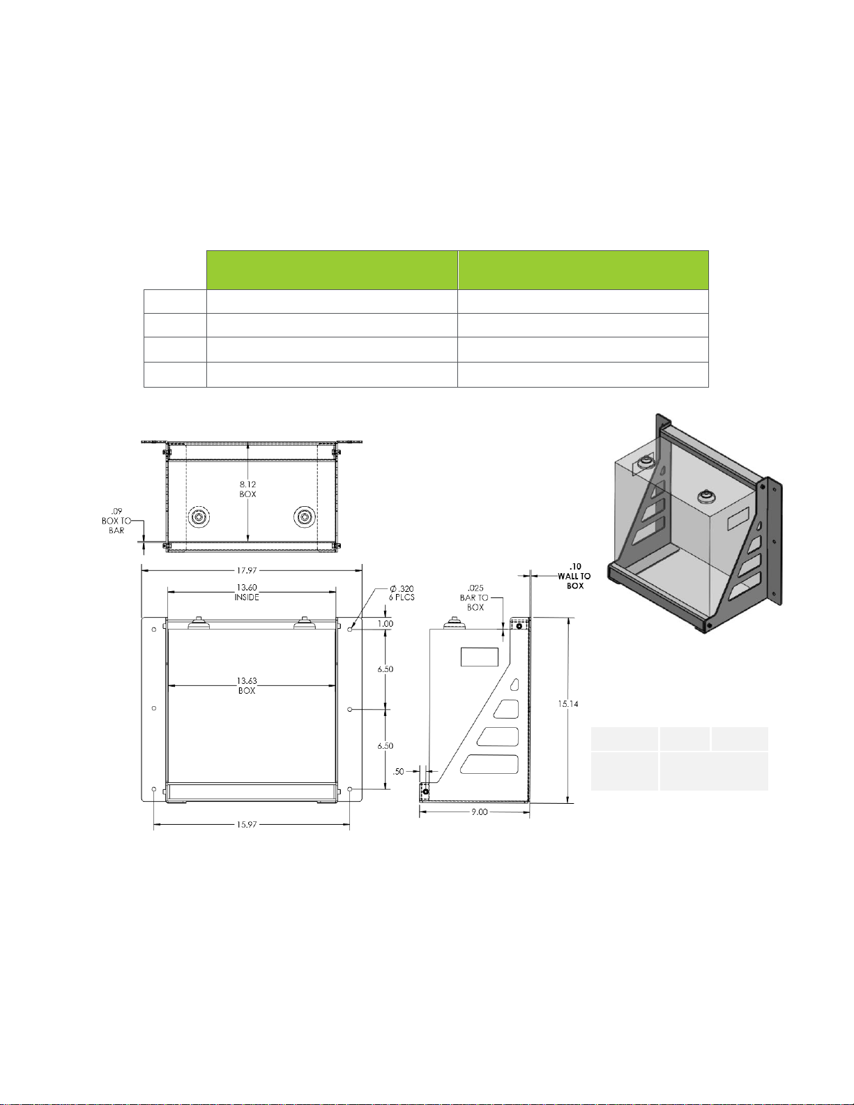
3.5 –Battery Wall Mount + Bracket Dimensions
Please see the tables below for physical dimensions of the PHI 3.8 and PHI 2.9 Battery both with, and
without, the SimpliPhi Power Mounting Bracket, as well as a diagram that provides guidance on Mounting
Bracket assembly.
Table 2.0 –Specifications: PHI 3.8 Battery v. PHI 3.8 Battery w/ Mounting Bracket
PHI 3.8 Battery
PHI 3.8 Battery
w/ Mounting Bracket
Width
13.5’’
13.7” (18” with mounting flanges)
Height
15.5’’ (including 1.5” terminal height)
15.75” (including 1.5” terminal height)
Depth
8”
9”
Weight
78.24 Pounds
86.24 pounds
Figure 2.0 –PHI 3.8 Mounting Bracket Assembly
Terminals
3/8 IN
10 MM
Battery
Cables
6 AWG MINIMUM*
PHI 3.8TM
BATTERY
WITH WALL MOUNT BRACKET
*local electrical codes may call
for other wiring requirements

REV073019
SimpliPhi Power, Inc. | 3100 Camino Del Sol | Oxnard, CA 93030, USA | (805) 640-6700 | info@simpliphipower.com | SimpliPhiPower.com
| 11 |
Table 3.0 –Specifications: PHI 2.9 Battery v. PHI 2.9 Battery w/ Mounting Bracket
PHI 2.9 Battery
PHI 2.9 Battery
w/ Mounting Bracket
Width
11.25’’
13.7” (15.5” with mounting flanges)
Height
12.75" (including 1.75” terminal height)
13” (including 1.75” terminal height)
Depth
9.5”
10.5”
Weight
61.06 Pounds
70.06 pounds
Figure 3.0 –PHI 2.9 Mounting Bracket Assembly
4.0 –Installation & Wiring
This section covers basic concepts of system configuration as well as how to increase storage capacity
by wiring in parallel.
4.1 –Basic System Configuration Concepts
Safe and reliable installation requires trained and certified technicians. The following discussion of PHI
Battery configurations is a basic primer. Due to the variety of systems and components in the field, all
possible scenarios are not covered. This is not the purpose of this section of the manual. Refer to
professional installers regarding your system and its components and specifications. We encourage you or
your installer to contact us with any specific questions for Technical Support. We are committed to working

REV073019
SimpliPhi Power, Inc. | 3100 Camino Del Sol | Oxnard, CA 93030, USA | (805) 640-6700 | info@simpliphipower.com | SimpliPhiPower.com
| 12 |
with you and your installation team to achieve a safe, reliable storage system that will provide years of
maintenance free service.
4.1.1 –System Wiring Basics
Refer to published electrical wiring specifications and ratings. All wire should be an appropriate
gauge and construction to handle the loads that will be placed upon it. Heavy gauge, high strand
copper wire is the industry standard due to its stability, efficiency and overall quality. A qualified
installer should understand this and must adhere to the industry standard and published electrical
guidelines.
For all installations:
•Maintain identical wire lengths from each PHI Battery terminal to the common bus.
•Use identical wire construction from each PHI Battery terminal to the common bus.
All PHI Batteries are designed to serve at a fixed voltage range in parallel arrangements for
maximum available amperage and storage capacity. PHI Batteries are not designed to be
arranged in series for increased voltage. Series arrangements can result in damage to the PHI
Battery’s protective circuitry and will void the Warranty.
4.1.2 –Increasing Storage Capacity & Simple Parallel
Arrangements
Storage Capacity and total available Amperage is increased incrementally with the number of
units in Parallel arrangements. The following illustration (Figure 4.0) shows two PHI Batteries in
Parallel. For example, assume that these are 24V PHI 3.8 Batteries.
Note: The overall Voltage range is not changed. For this example, the arrangement remains at
24 Volts, while the available AH capacity (ability to provide 24 Volt power over time) has been
doubled with the addition of a second PHI 3.8 Battery. The same configuration and calculation
should be applied to other parallel arrangements, whether they are 12V, 24V or 48V. See Figure
4.0.
CAUTION: PHI Batteries are designed for parallel operation only. Do not arrange in series for
increased voltage. Wiring in series will void theWarranty.
Figure 4.0 –Two PHI Batteries in Parallel

REV073019
SimpliPhi Power, Inc. | 3100 Camino Del Sol | Oxnard, CA 93030, USA | (805) 640-6700 | info@simpliphipower.com | SimpliPhiPower.com
| 13 |
Figure 4.0 represents two PHI Batteries in Parallel. Wire lengths from PHI Batteries should be
identical in length and gauge in order to balance the load across (all) PHI Batteries in the
installation. Identical wiring length is a critical feature of parallel power storage systems
that must be adhered to throughout all parallel wiring instructions. Failure to wire in
parallel will void the Warranty.
Special attention should be paid for parallel installations. Correct wiring is essential to insure
optimum performance and system longevity. All wire “runs” should utilize identical wiring gauge
and identical wire lengths between PHI Batteries and the common negative or positive “Bus” or
Load. Figure 5.0 depicts four PHI Batteries that have been wired in Parallel. This configuration
requires 8 identical lengths of appropriately heavy gauge copper wire.
Figure 5.0 - Four PHI Batteries in Parallel
Helpful Tips:
•Use identical length and gauge wire to balance the load across the PHI Batteries.
•Determine the cable length for the PHI Battery terminal farthest from the bus first.
•Make all PHI Battery cables a matching length.
•Additional cabling or slack that remains with the shorter distance runs can be coiled
and secured with Zip Ties.
Wiring Methods:
1. For 1 to 8 units: Wire directly to inverter & charge controller equipment.
2. For 6 to 20 units: Use a DC combiner or panelboard.
3. For 20+ units: Connect the PHI Battery terminals directly to a common bus.
4. Positive wire runs should be separated from negative wire runs in separate conduit.
4.2 –Torque Values
For the terminals on the PHI Batteries with threaded stud DC terminals, torque to 160 in-lbs. (13.3 ft-lbs.).
4.3 –Battery Wiring Methods
4.3.1 –Connecting Cable Leads to the PHI Batteries
Before connecting the cable leads to the PHI Battery, please be aware of the following
information concerning power cabling, considerations for power cable terminations as well as
installation environments.
CAUTION: Spark may be present when connecting wires to PHI terminals.

REV073019
SimpliPhi Power, Inc. | 3100 Camino Del Sol | Oxnard, CA 93030, USA | (805) 640-6700 | info@simpliphipower.com | SimpliPhiPower.com
| 14 |
CAUTION: Do not reverse polarity. It will void the Warranty. Use a volt meter to check polaritybefore
making connections to battery terminals or Anderson Connectors. A brief small spark is often present
when connecting the second of two leads to a PHI Battery terminal. Example: If the Positive has
been connected, a small spark will likely be present when connecting the Negative lead. This is a
normal occurrence. Complete all connections in a clean, ventilated, well-lit area. To avoid any
spark or electrical event when connecting the terminal leads, make the connection with the circuit
breaker in the “OFF” position. To avoid any spark or electrical event when connecting batteries
with Anderson Connectors, turn the accompanying equipment off, connect cables with
appropriate battery mating connectors to the equipment, and then make final connections via
connectors to the batteries before turning on the system’s accompanying equipment.
Power Cabling for the PHI Battery is not included. Your qualified installer or application
specifications will determine the wire gauge for your system. Connection to the PHI Battery
should only be made using appropriately sized ring terminals or mating connectors. Your installer
can source these.
Considerations for Power Cable Terminations
Please factor in the below information for power cable terminations:
•PHI Battery models with threaded studs –Stud Size: 3/8’’
•PHI Battery models using SB50 Anderson Connectors
o12V connections are YELLOW
o24V connections are RED
•Power Cable Wire Gauge: Generally anywhere from 6 AWG to 2/0 AWG or larger
Protection from the Environment
Anticorrosive compounds or epoxies are occasionally used in harsh or marine climate
installations. Please contact your Electrician or Qualified Installer to determine if this is advisable,
and if so, what solution best suits your application.
4.3.2 –Final Connection of the Installation
Final installation and operation guidelines will be dictated by your Electrician and Installer based
on the overall properties of and procedures for the equipment in your installation and any code
requirements that apply to your region. SimpliPhi Power, Inc. technicians and sales staff are
available to provide any additional information on the PHI Battery as needed. Please contact
SimpliPhi Power for any technical support at your convenience. SimpliPhi Power, Inc. is
committed to providing safe, reliable energy storage and management that is maintenance free,
non-toxic and long-lasting. This commitment extends to our customers, valued installers,
partners, and to the community at large. Please be aware of the potential electrical hazards
before interacting with any and all electrical or mechanical devices. Please take all necessary
precautions in your projects and installations. Please refer to Section 1 for safety guidelines.
PHI Batteries feature a Low Battery Voltage Cut Off (LBCO). This is a self-protection mechanism
that prevents over discharge. The LBCO will cause the PHI Battery to turn off once batteries
approach Zero Capacity or 100% Depth of Discharge.
Most, if not all, inverters have related features. These features are often referred to as “Load
Disconnect”, “Load Shedding” or similar. These features are there to protect the PHI Battery bank
from excessive discharge. In instances of low battery voltage, when there is no incoming energy
to recharge the PHI Battery bank, the inverter will disconnect the load and remain in standby until
the PHI Battery bank is recharged.
For off grid installations, where charge energy is only provided by renewable energy such as PV
arrays, Inverter “Load Disconnects” are generally set at a value that will allow a system to remain
online and in standby for at least 24 hours (10% at top of charge and 10% at bottom of charge).

REV073019
SimpliPhi Power, Inc. | 3100 Camino Del Sol | Oxnard, CA 93030, USA | (805) 640-6700 | info@simpliphipower.com | SimpliPhiPower.com
| 15 |
This allows a system to stay online until at least one full day of sun can recharge the PHI Battery
bank.
In any application, off-grid or grid-tied, if your PHI Battery bank is reaching the LBCO, load
disconnects or load shedding set points may need to be adjusted. Refer to Programming section.
In case of LBCO, cycle the DC Battery Disconnect (inverter), in order to reset the system. Only
complete this procedure when there is a charge source available, otherwise, the system will
simply reach LBCO in a short time period and shut down again.
4.4 –Battery Bank Expansion
New SimpliPhi batteries that are added to an existing SimpliPhi battery bank must be of the same
nameplate voltage form factor. The battery bank’s total energy capacity is the sum of the
differently-rated batteries. For example, a battery bank composed of one PHI 3.5 battery and one
PHI 3.8 battery has a total energy storage capacity of 7.3 kWh for the bank (3.5 kWh + 3.8 kWh).
CAUTION: Do not combine PHI Batteries with other brands or chemistries. This will void the Warranty.
Add new additional SimliPhi batteries to an existing SimpliPhi battery bank within the first three
years or the original SimpliPhi battery bank’s commissioning date. Consult SimpliPhi Power
Technical Support if you wish to expand a SimpliPhi battery bank beyond the three year mark.
In addition to adhering to all other Installation Manual instructions, refer to the following guidelines
when expanding upon an existing SimpliPhi battery bank:
1. Charge the existing battery bank (“Bank A”) according to normal charging procedure (PHI
batteries charge to 54.4V / 27.2V / 13.6V and “rest” at approximately 52.5 - 53.5V / 26.1V -
26.7V / 13.1 - 13.3V after being taken off a charge).
2. Disconnect Bank A from the system, by either
a. Disconnecting all battery cables leading from Bank A’s batteries to the battery
combiner box, panelboard, or inverter’s power panel, OR
b. Turning off the 80A breakers included in each of Bank A’s batteries
3. Connect the additional batteries (Bank B) to the system, following all wiring instructions
and torque specifications outlined in previous sections of segment 4.0 in this manual.
4. Modify the settings in the system’s inverter/charger(s) or charge controller(s), whichever
device will be used to intially charge Bank B.
a. Adjust the charge rate in accordance with the number of batteries in Bank B
5. Charge Bank B fully, making sure all loads are disconnected at the time of initial charge
6. Wire all Bank A batteries and Bank B batteries in parallel, adhering to the wiring methods
outlined in Section 4.3 above.
a. Ensure that DC Positive common bus and DC Negative common bus ratings are
appropriate for the new larger quantity of batteries in the bank.
7. Reprogram all inverter/charger and/or charge controller equipment for the new larger
battery bank capacity.
a. New charging current parameters for the expanded bank should be appropriate for
the oldest included PHI battery model. For example, a battery bank composed of
one PHI 3.5 battery with a maximum continuous charge rate of 34 Amps DC and
one PHI 3.8 battery with a maximum continuous charge rate of 37.5 Amps DC has
a combined maximum continuous charge rate of 68 Amps DC (not 71.5 Amps DC).

REV073019
SimpliPhi Power, Inc. | 3100 Camino Del Sol | Oxnard, CA 93030, USA | (805) 640-6700 | info@simpliphipower.com | SimpliPhiPower.com
| 16 |
5.0 –Programming
5.1 –Operating Parameters per Warranty
Although the PHI Batteries are capable of performing at very high rates and depths of discharge within a
very wide temperature range, in order to achieve extended life cycles and to comply with the Warranty,
the operating parameters, indicated in Tables 4.0 and 5.0 below, must be applied based on desired
Warranty/cycle life. Refer to the manufacturer-specific Integration Guide from SimpliPhi’s Product
Documentation web page for a complete list of settings: https://simpliphipower.com/product-
documentation/.
Table 4.0 –Warranty Operation Parameters
Recommended Operating Conditions for 10 Year Warranty
Equivalent to 80%
Retained Capacity
10,000 cycles
5,000 cycles
3,500 cycles
Discharge/Charge Rate1,2
C/2
DoD4
80%
90%
100%
Operating Temperature
°F (°C)
32 to 120 (0 to 49)
Programming Settings
for Ancillary Equipment
12V
24V
48V
12v
24V
48V
12V
24V
48V
Absorb / High Cut-Off
Voltage (V)3
13.6
27.2
54.4
13.6
27.2
54.4
14
28
56
Absorb Time
1 Hour
1 Hour
1 Hour
Recharge / Low Cut-Off
Voltage (V)3
12.6
25.1
50.2
12.4
24.8
49.6
12
24
48
The charge cycle should be programmed to 2 Stage / No Float. Utilizing a Float Charge is permissible
only in charge controllers’ programming. Refer to the relevant charge controller Integration Guide for
complete charge controller settings.
Table 5.0 –Operating Limitations
Notes / Operating Limitations for
PHI Batteries
PHI 3.8
PHI 2.9
PHI 1.4
PHI 730
Limitations by Model
24V
48V
24V
48V
24V
12V
24V
12V
Continuous
Discharge Rate (A)
45
37.5
45
28.5
28.5
40
14
28.5
Continuous Charge
Rate (A)
45
37.5
45
28.5
28.5
40
14
28.5
•60A Discharge/Charge Rate (10 minutes maximum)
•Levels are typically @ 25°C and may need adjusting at temperature extremes.
•When performing rapid deep charge/discharge cycles, the PHI Battery should be allowed to "rest" 15 mins in
between.

REV073019
SimpliPhi Power, Inc. | 3100 Camino Del Sol | Oxnard, CA 93030, USA | (805) 640-6700 | info@simpliphipower.com | SimpliPhiPower.com
| 17 |
Although the PHI battery charges to the voltages outlined above, the battery “rests” at
approximately 13.3V / 26.7V / 53.3V. Refer to Table 6.0 below for a complete Battery Voltage
versus State of Charge (SOC) gauge.
Table 6.0 –Battery Voltage VS. State of Charge (SOC)
SOC
12V
24V
48V
100%
> 13.13 VDC
> 26.25 VDC
> 52.5 VDC
95%
12.93
25.9 VDC
51.7 VDC
90%
12.91
25.8 VDC
51.65 VDC
75%
12.85
25.7 VDC
51.4 VDC
50%
12.75
25.5 VDC
51.0 VDC
20%
12.55
25.1 VDC
50.2 VDC
10%
12.38
24.8 VDC
49.5 VDC
0%
12.0
24.0 VDC
48.0 VDC
CAUTION: Verify polarity at all connections before energizing system. Reverse polarity at the PHI Battery
terminals will void the Warranty and destroythe PHI Batteries.
CAUTION: Before commissioning the system the appropriate controller and inverter settings must be
programmed per the manufacturer’s recommendations. Consult the manufacturer’s manuals and/or the
Integration Guides listed on SimpliPhi’s Product Documentation web page (Schneider, Magnum,
Outback, etc.). The following Charge Controller Integration tables are for general reference only.
CAUTION: All SimpliPhi Power Core Power and Peak Power products are designed to work exclusively in
parallel. Never connect in series to achieve higher voltages.
6.0 –SimpliPhi Technical Support
For technical support related to your PHI Battery, please contact us as follows:
805.640.6700
techsupport@simpliphipower.com

REV073019
SimpliPhi Power, Inc. | 3100 Camino Del Sol | Oxnard, CA 93030, USA | (805) 640-6700 | info@simpliphipower.com | SimpliPhiPower.com
| 18 |
Appendix A –PHI Battery Safety & Green
Attributes, Certifications
This Appendix section covers the PHI Battery safety attributes and certifications, such as the lack of
thermal runaway and off-gassing, UN DOT certification and UL compliance and certification. It also covers
the PHI Battery’s green attributes – from products to materials to disposal, as well as relevant
environmental and ecological considerations.
B.1 –Safety Attributes and Certifications
B.1.1 –Intrinsically Safe Operation and Installation
The PHI Lithium Ferrous Phosphate (LFP) battery cell component is made with an intrinsically
safe cathode material (iron phosphate). This creates a strong molecular bond, which withstands
extreme conditions, prolongs cycle life, and maintains integrity with little or no maintenance over
extended periods of time. There is virtually no danger of Thermal Runaway, as there may be with
Lead Acid, NiCd, and Lithium Cobalt type batteries (NCA, NMC, LCO). No venting or cooling is
required. No precautions or special structural considerations are necessary when installing PHI
Batteries.
B.1.2 –No Safety Hazards due to Off-Gassing, Exposure to
Acids, Thermal Runaway
PHI Batteries do not vent dangerous gasses, such as hydrogen and oxygen, because there are
no chemicals used in the creation of the electrical energy, in contrast to Lead Acid and other
battery chemistries. There are no dangers of exposure to sulfuric acid because PHI Batteries do
not have caustic electrolytes. Thermal runaway is not an issue with PHI products due to the basic
nature of Lithium Ferro Phosphate cell chemistry utilized in all our power storage products.
B.1.3 –PHI Battery Control and Protective Circuitry
SimpliPhi Power Inc. utilizes balancing, voltage regulation, thermal, current controls, as well as
other protective measures, in its PHI Battery Management System (BMS). This protective circuitry
is embedded in the architecture of each PHI Battery.
B.1.4 –UN DOT Certified Cells
The Lithium Ferrous Phosphate (LFP) cells are independently certified to withstand the UN DOT
T1-T8 testing guidelines with no special circuitry added. These tests include short circuit, over-
voltage, overcharging, extreme temperature, high altitudes, shock and extreme vibration testing.
B.1.5 –UL Compliance
The Lithium Ferrous Phosphate cells within the PHI Batteries fully comply with the safety testing
parameters of UL 1642.
B.1.6 –RoHS Compliant
SimpliPhi Power 3.8 Batteries are RoHS compliant. Any RoHS compliant component is tested for
the presence of Lead (Pb), Cadmium (Cd), Mercury (Hg), Hexavalent chromium (Hex-Cr),
Polybrominated biphenyls (PBB), and Polybrominated diphenyl ethers (PBDE). For Cadmium and
Hexavalent chromium, there must be less than 0.01% of the substance by weight at raw
homogeneous materials levels. For Lead, PBB, and PBDE, there must be no more than 0.1% of
the material, when calculated by weight at raw homogeneous materials. Any RoHS compliant
component must have 100 ppm or less of mercury and the mercury must not have been
intentionally added to the component. In the EU, some military and medical equipment are
exempt from RoHS compliance.

REV073019
SimpliPhi Power, Inc. | 3100 Camino Del Sol | Oxnard, CA 93030, USA | (805) 640-6700 | info@simpliphipower.com | SimpliPhiPower.com
| 19 |
B.2 –Green Attributes, Environmental & Ecological Considerations
B.2.1 –Materials
The primary materials (lithium, iron, phosphate) that make up PHI Batteries are environmentally
benign and pose very few polluting or environmentally degrading by-products in the harvesting
and refinement processes. This is especially true when compared to those of lead acid, NMC,
NCA, LCO, NiCad, and NiMH batteries.
B.2.2 –By Products
There are no toxic by-products associated with the manufacturing or use of PHI Batteries, such
as off-gassing hydrogen, sulfuric acid spillage, lead contamination, or explosive chemicals.
B.2.3 –Operation
There is no need for maintenance, such as adding water or chemicals, nor is there corrosion of
terminals or containment facilities, or dispersion of fumes as with other battery types. Once
installed, PHI Batteries are maintenance free.
B.2.4 –Life Cycles
PHI Batteries are designed for thousands of cycles while maintaining 80 percent or more of their
initial capacity. To achieve this, it is critical to follow the operating conditions outlined in the
Warranty.
B.2.5 –Disposal
PHI products are non-hazardous, may be disposed of without damage to the ecosystem, and
returned to the earth, while easily recombining with the elements without harmful by-products.
The outer casing and brackets contain steel, aluminum, copper, cardboard, and recyclable
plastic. Lithium Ferrous Phosphate (LFP) materials can also be recycled through established
battery centers if desired.
B.2.6 –Lithium Ferrous Phosphate Batteries and the
Environment
As the use of this battery chemistry in larger batteries becomes more common, questions of
sustainability and environmental impact inevitably arise. Of the lithium ferrous phosphate
chemistries being considered for large format batteries, SimpliPhi Power believes that batteries
based on our proprietary lithium ferrous phosphate chemistry and circuitry offer a clear
advantage, not only over alternate Li-ion chemistries (lithium cobalt oxide), but all battery
chemistries that are currently commercially available. This belief is based on the minimal
environmental impact associated with the manufacturing of PHI Batteries, the extended cycle life
and the significantly smaller end-of-life footprint that results from the use of PHI Batteries.
B.3 –Summary
The Lithium Ferrous Phosphate (LFP) cells utilized throughout the entire PHI and LibertyPak product
lines are classified as non-hazardous by OSHA and WHMIS. They are non-toxic, unlike NMC, NCA, LCO,
NiMH, NiCad or Lead Acid types of batteries (including AGM). The PHI Batteries contain the least amount
of toxic metals, and are the most eco-friendly of all common battery types. Lithium easily combines into
harmless compounds when disposed of. The PHI Batteries are the least polluting rechargeable batteries
on the market today –no fumes, leaking, or gas discharge and no chemicals or acids to worry about.
Designed and Manufactured in the USA Using Exclusive American Patented Technologies.

REV073019
SimpliPhi Power, Inc. | 3100 Camino Del Sol | Oxnard, CA 93030, USA | (805) 640-6700 | info@simpliphipower.com | SimpliPhiPower.com
| 20 |
Appendix B –PHI Approved External Chargers
This Appendix section covers the PHI Battery’s approved external / plug-in chargers.
Typically, ancillary charging of SimpliPhi’s batteries is not required, and charging using any of the
charge controllers and/or inverter/chargers listed in the “Integration Guides” section of the SimpliPhi web
site’s Product Documentation page is acceptable. However, ancillary charging may be necessary in the
following situations:
1. No charge controller or inverter/charger is available
2. Increasing the battery’s State of Charge (SoC) after an extended storage period and prior to
installation
3. For recharge purposes when the battery’s voltage is below the minimum required voltage for
charge controller and/or inverter/charger equipment to turn on
C.1 –Recommended 48V Charger
The 54.6V 4A 13 Series 48V LiFePO4 Smart Charger from WAOUKS is recommended and available
online for purchase at this link.
The 58.4V 5A 16 Series 48V LiFePO4 Smart Charger from WAOUKS is recommended and available
online for purchase at this link.
C.2 –Recommended 24V Charger
The 29.2V 7A 8 Series 24V LiFePO4 Smart Charger from WAOUKS is recommended and available
online for purchase at this link.
C.3 –Recommended 12V Charger
The 14.6V 20A 4 Series 12V LiFePO4 Smart Charger from WAOUKS is recommended and available
online for purchase at this link.
When placing your order, specify the connection type to match your battery model. PHI 3.8 and PHI 2.9
model batteries require a charger with alligator clips or crocodile clips, whereas PHI 1.4 and PHI 730
model batteries require a charger with Anderson Connectors.
C.4 –Alternative Chargers
If the above listed chargers are unavailable or undeliverable to your specific location, SimpliPhi also
approves of Iota Engineering’s battery chargers (link here) to increase the PHI battery’s voltage. These
chargers should only be used in order to increase battery voltage enough to regain system operability;
these chargers should not be used to regularly and fully charge the PHI battery.
Other manuals for PHI 3.8 Series
1
This manual suits for next models
3
Table of contents
Other SimpliPhi Camera Accessories manuals


Popular Camera Accessories manuals by other brands


ARK Battery
ARK Battery Legendary Power 100AH 48V Installation Guide & Specifications

Juicebox
Juicebox Magic Power JBMP-02 manual

Mastervolt
Mastervolt MLI-E 12/1200 User and installation manual

Waveshare
Waveshare Pan-Tilt HAT user manual

RedEarth
RedEarth HoneyBadger user manual

Aputure
Aputure Gigtube Wireless II user manual