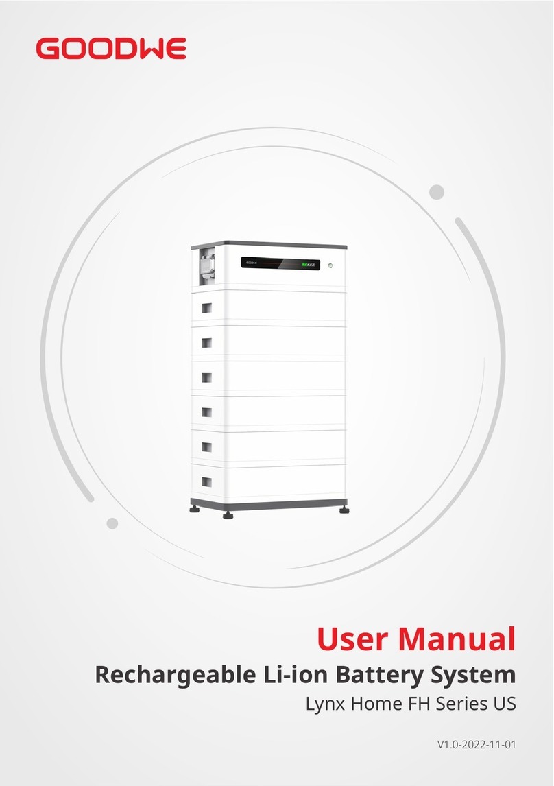
Goodwe Lynx C Series User manual

Rechargeable Li-ion Battery System
Lynx C Series
V 1.0 2022-10-15
User Manual

I
Copyright Statement
User Manual V1.0-2022-10-15
The information in this user manual is subject to change due to product updates or other rea-
sons. This guide cannot replace the product labels or the safety precautions in the user manual
and other GOODWE trademarks are trademarks of GoodWe Technologies
GoodWe Technologies Co.,Ltd.
Trademarks
NOTICE
No part of this manual can be reproduced or transmitted to the public platform in any form or
by any means without the prior written authorization of GoodWe Technologies Co., Ltd.
Copyright ©GoodWe Technologies Co., Ltd., 2022. All rights reserved

II
CONTENT User Manual V1.0-2022-10-15

III
CONTENT
User Manual V1.0-2022-10-15

IV
01 About This Manual User Manual V1.0-2022-10-15
01 About This Manual
1.1 Applicable Model
1.2 Target Audience
This manual describes the product information, installation, electrical connection, commissioning,
troubleshooting and maintenance of Lynx C Series Rechargeable Li-ion Battery System for
Commercials and Industries (hereinafter referred to as the Lynx C BMS in short). Read through
familiar with the product features, functions, and safety precautions. This manual is subject to
com.
This manual applies to trained and knowledgeable technical professionals. The technical
personnel has to be familiar with the product, local standards, and electric systems.
Model Usable Energy (kWh)
LX C101-10 101.38
LX C120-10 119.81
LX C138-10 138.24
LX C156-10 156.67
DANGER
CAUTION
NOTICE
1.4 Updates
The latest document contains all the updates made in earlier issues.
V1.0 2022-10-15
First Issue

02 Safety PrecautionUser Manual V1.0-2022-10-15
01
02 Safety Precaution
NOTICE
The Lynx C BMS are designed and tested strictly in compliance with related safety rules. Read
and follow all the safety instructions and cautions before any operations. Improper operation
might cause personal injury or property damage as the products are electrical equipment.
2.1 General Safety
NOTICE
• The information in this user manual is subject to change due to product updates or other
reasons. This guide cannot replace the product labels or the safety precautions in the user
• Read through this document before installation to learn about the product and the
precautions.
•
familiar with local standards and safety regulations.
•
Lynx C BMS products to ensure personal safety.
•
manufacturer shall not be liable for equipment damage or personal injury if you do not
.
2.2 Installation Precaution
WARNING
•
precautions outlined in this manual and safety labels on the equipment.
•
Only professionals are allowed!
•
•
•
•
connection. Otherwise the short circuit may cause personal injuries and damage to the
equipment.

User Manual V1.0-2022-10-15
02
02 Safety Precaution
Symbol Description Symbol Description
operations.
Install the equipment away from
equipment's running.
before any operations.
children.
Operate the equipment properly to No extinguishing with water.
electrolytes. In case of a leak in
leaked liquid or gas.
Do not dispose of the equipment
with household garbage at its end
of life. Dispose it according to local
laws and regulations. Or send it to
the manufacturer.
and recycle it in compliance with
Read through the user manual
before any operations. during installation, operation and
maintenance.
No stepping. connection position.
CE Marking. TUV Marking.
RCM Marking. --
Symbol Description
•
• Warning labels on the BMS are as follows.

02 Safety PrecautionUser Manual V1.0-2022-10-15
03
•
•
•
•
•
com.
WARNING
•
•
Rinse your eyes for at least 15 minutes with clean water and seek immediate medical
assistance.
•
Thoroughly wash the touch area with soap and clean water, and seek immediate medical
assistance.
•
2.5 Emergency Measures
2.4 Battery Safety
WARNING
• Do not charge the battery at lower temperature. Otherwise it may decrease the capacity of
the BMS.
•
•
2.3 Maintenance Precaution
WARNING
• Do not pull or plug the terminals and connecting cables during the running of the BMS.
Otherwise it may cause dangers to the safety.
•
•
Contact the related personnel as soon as possible.
•
with sharp objects, or put unrelated items into any part of the battery cabinet.
2.6 EU Declaration of Conformity

03 Product Introduction User Manual V1.0-2022-10-15
04
• This manual is mainly about product introduction, application scenarios, installation,
commissioning, maintaining and technical parameters of the Lynx C BMS.
•
cabinet.
•
03 Product Introduction
3.1 Product Overview
BMS Model PCU Quantity Battery Cabinet Quantity Battery Module Quantity
LX C101-10 1 1 11
LX C120-10 1 1 13
LX C138-10 1 1 15
LX C156-10 1 1 17

User Manual V1.0-2022-10-15 03 Product Introduction
05
3.2 Battery Cabinet
Length Width
Height
Front View Right View Left View
Model Length (mm) Width (mm) Height (mm)
LX C101-10 1155 730 1650
LX C120-10
LX C138-10 1155 730 2065
LX C156-10
Handle
BMS Routing Hole
Slot

03 Product Introduction User Manual V1.0-2022-10-15
06
3.3 PCU
No. Silk Print Parts Description
1 B+ terminal module.
2 QF3 DC circuit breaker Used when the BMS is self-powered.
3 QF2 Used when the BMS requires external power supply.
4 QF1 Main circuit
breaker The main circuit breaker for the BMS.
5 HRL Indicator To display the working status of BMS.
6 B- terminal module.
7output port
8port
9 output port
10 COM External COM
port
11 BMU
COM Internal COM port To connect the battery module for communication.

User Manual V1.0-2022-10-15 03 Product Introduction
07
3.5 Battery Module
No. Parts Description
1Connector for battery
communication communication.
2-
3-
4 Battery hoisting hole To hoist the battery modules into the cabinet.
5
525mm
677mm
202mm
3.4 Indicator
No. Red Green Description
1
-
ON The BMS is in operation.
2The BMS is in idle status.
3The BMS is on standby.
4
-
Slight alarm
5 Medium alarm
6 ON

03 Product Introduction User Manual V1.0-2022-10-15
08
3.6 Nameplate
GOODWE trademark, product type, and
product model
Technical parameters
Contact information and serial number
The nameplate is for reference only.

User Manual V1.0-2022-10-15 04 Storage and Package
09
04 Storage and Package
4.1 Storage Environment
If the equipment is not to be installed or used immediately, please ensure that the storage
•
•
• If the battery modules are going to be kept for more than 30 days, adjust SOC to 40%-60%
•
•
there is moisture or condensation.
•
•
•
•
•
•
4.2 Packing List
• The packing of the BMS is mainly composed of the packages of the battery modules and the
battery cabinet.
•
•
Battery Module
Battery Module x N
No. Model Battery Module Quantity (Pieces)
1 LX C101-10 11
2 LX C120-10 13
3 LX C138-10 15
4 LX C156-10 17

04 Storage and Package User Manual V1.0-2022-10-15
10
•
•
Accessories LX C101-10 LX C120-10 LX C138-10 LX C156-10
Battery power connecting bar
(pieces) 9 11 13 15
Battery COM cable (pieces) 10 12 14 16
M6 screw (pieces) 56 56 72 72
M8 screw (pieces) 24 28 32 36
Sealing plate (pieces) 2 0 2 0
Battery Cabinet and Accessories
Battery cabinet x 1*1 COM connector x 1 connector x 1
Battery power Battery power
connecting bar B x 1
Battery power
connecting bar C x 1
Battery power
connecting bar D x 1
COM cable between COM cable between
batteries x N M6 screw x N M8 screw x N
Mounting hook x 4 Sealing plate x N

User Manual V1.0-2022-10-15 05 System Installation
11
5.1 Installation Environment
•
on.
• The BMS shall be installed indoor.
•
•
•
• Do not install the equipment in a place where the temperature changes extremely.
• Install the equipment away from strong interferences.
•
• Do not install the equipment in places prone to accumulate water.
• near the equipment.
•
apparatus.
5.2 Space Requirements
05 System Installation
300mm
600mm 600mm
600mm

05 System Installation User Manual V1.0-2022-10-15
12
CAUTION
injury or equipment damage.
1.
2.
5.4 Moving the BMS
5.3 Angle Requirements
5.5 Installing the BMS
NOTICE
•
•
inclination.

User Manual V1.0-2022-10-15 05 System Installation
13
Step 1
Step 2 Open the battery cabinet and take out the accessory package.
Step 3
Step 4
cabinet from bottom to top. For LX C101-10 and LX C138-10, do not install any battery module
on the top layer.
Step 5
used on the top layer for LX C101-10 and LX C138-10).

05 System Installation User Manual V1.0-2022-10-15
14
30-100mm
M6
4.5-6N·m
15
1
2
3
4
5
6
7
8
9
10
11
12
13
14
16
1
2
10
3
11
4
12
5
13
6
14
7
15
8
9
17

User Manual V1.0-2022-10-15 06 Electrical Connection
15
NOTICE
•
during dismantling the equipment.
•
2.
LL
06 Electrical Connection
WARNING
•
connections.
•
the insulation layer of the cables may be aging or broken due to high temperature.
•
apart. Do not place the cables entangled or crossed.
M5
3.5-4.5N·m
6.1 Connecting PE Cable
Other manuals for Lynx C Series
4
This manual suits for next models
4
Table of contents
Other Goodwe Camera Accessories manuals
Goodwe
Goodwe ET Series User manual

Goodwe
Goodwe Lynx Home U Series User manual

Goodwe
Goodwe Lynx Home U Series User manual

Goodwe
Goodwe Lynx C Series User manual

Goodwe
Goodwe SECU-A Series User manual
Goodwe
Goodwe Lynx Home F Series User manual

Goodwe
Goodwe Lynx Home F Series User manual

Goodwe
Goodwe Lynx Home F Plus+ Series User manual

Goodwe
Goodwe Lynx Home S Series User manual
Goodwe
Goodwe Lynx C Series User manual